Makita PM7650H Manual

PRODUCT
P 1/26
Models No. PM7650H
Description Petrol Mist Blower
Model PM7650H is a Petrol mist blower equipped with
75.6cm³ 4-stroke engine in compliance with all major
exhaust emission regulations in the world, and features
16m max. horizontal spraying range and ergonomically
designed chemical tank.
This product is also available with E25 compatibility
for Brazil only as Model PM7650HG.
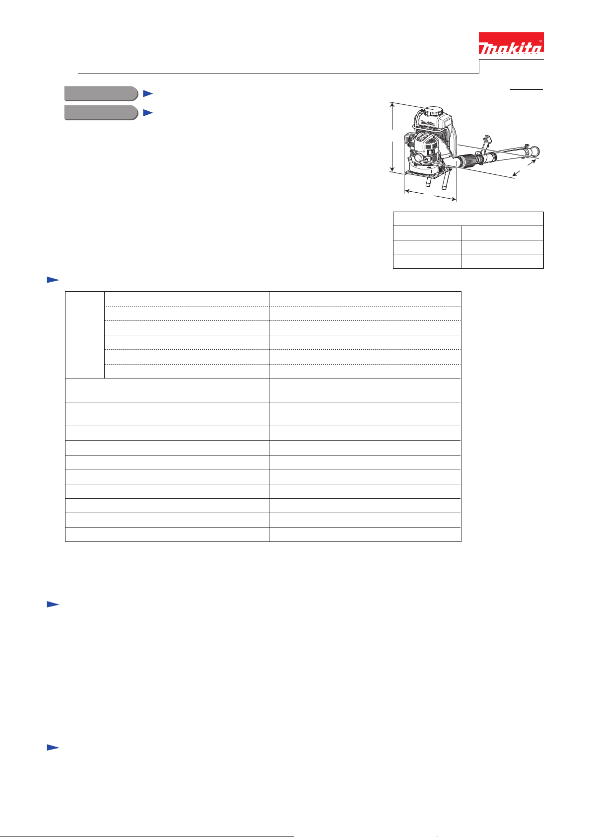
Dimensions: mm (")
Width (W)
Height (H)
Length (L)
440 (17-1/4)
420 (16-1/2)
595 (23-1/2)
Diaphragm
75.6 (4.61)
2.7 (3.67) [at 7,000 min.ˉ¹]
Carburetor
Yes
Max. engine speed: min.ˉ¹ = rpm
Idling speed: min.ˉ¹ = rpm
Starting system
Engine
Displacement: cm³ (cu.in)
Max. output power: kW (PS)
4-strokeType
Max. spray range (horizontal): m (ft)
Dry weight*4: kg (lbs)
*1 Brazil: E25 gasoline
*2 This product is not in compliance with the regulations of San Dimas.
*3 with nozzle
*4 with Straight pipe 330
13.3 (29.3)
Recoil starter, with mechanical decompression
16.0 (52)
Max. air velocity: m/s
Max. air volume*3: m³/h
85
845
7,400
2,800
Fuel Straight gasoline*1
CONCEPT AND MAIN APPLICATIONS
Specification
Compliance with exhaust emission regulations*2;
CARB Tier 3, EPA Phase 2, EU Stage 2
SAE10W-30 oil
in Class SF or higher of API Classification
Engine oil
1.8 (61)Fuel tank capacity: L (US oz)
Chemical tank capacity: L (US oz) 15.0 (507)
TECHNICAL INFORMATION
H
W
L
Note: The standard equipment for the tool shown above may vary by country.
Oil bottle (containing 220ml of oil) ......... 1
Hand strap ............................................... 1
Box wrench ............................................. 1
Screwdriver ............................................. 1
Diffusion cover
(Wide spray attachment) ......................... 1
Hose clamp 76 ......................................... 3
Hose clamp 100 ....................................... 1
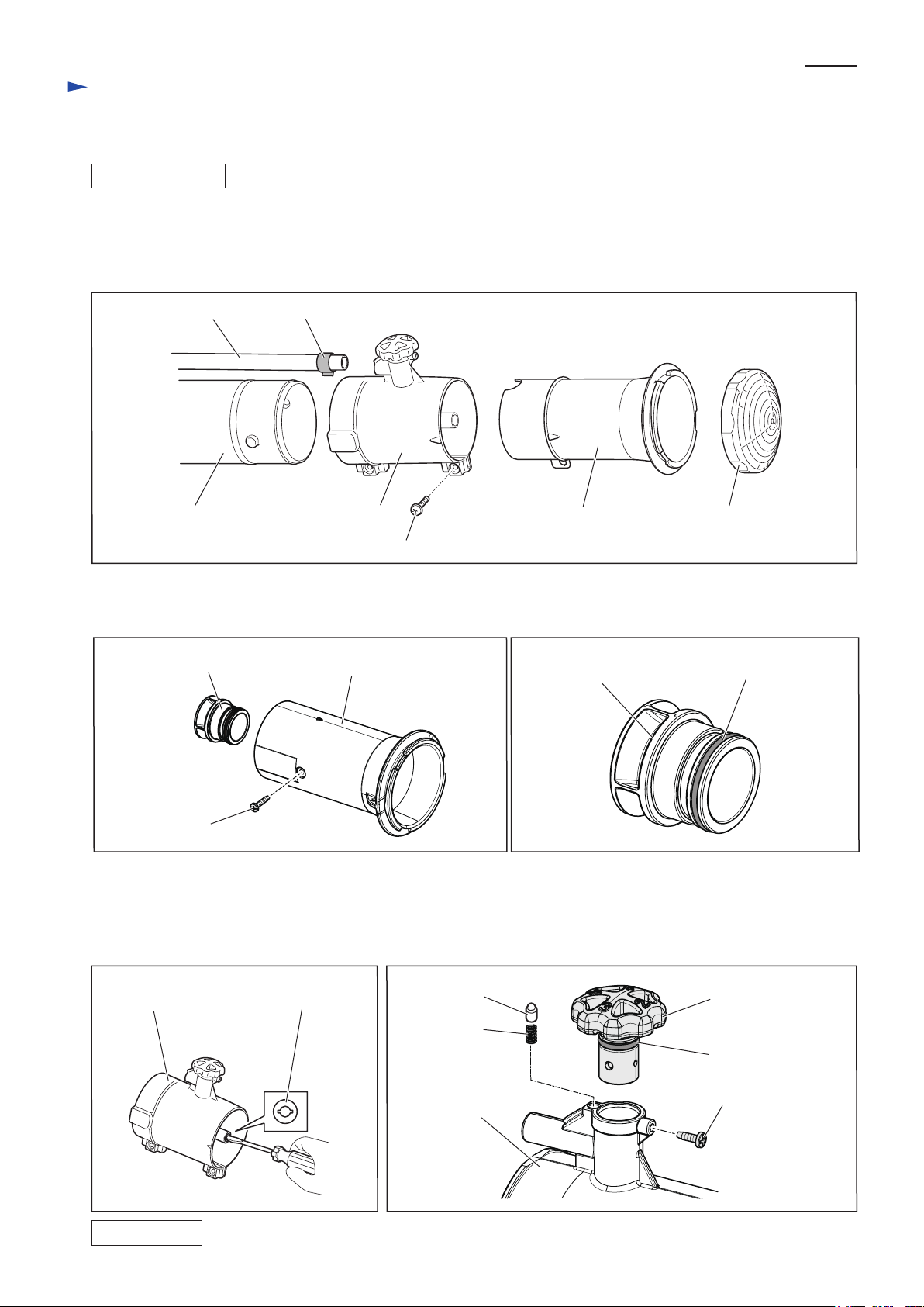
Flexible pipe ............................................ 1
Straight pipe 330 ..................................... 1
Straight pipe 330
Straight pipe 630
Bent top pipe 630 (20º)
O ring set
Air cleaner element
Nozzle 0.7
Nozzle 0.8
Standard equipment
Optional accessories
Straight pipe 630 (for Brazil only)
Bent top pipe 630 (20º) (for Brazil only)
Tube 10-500 (for Brazil only)

Repair
CAUTION: Repair the machine in accordance with “Instruction manual” or “Safety instructions”.
[4] DISASSEMBLY/ASSEMBLY
[4]-1. Warning
Follow the instructions described below in advance before repairing:
Wear gloves.
When the engine is hot from use, cool down the engine enough or you can get burned.
Remove remaining fuel from Fuel tank and Carburetor completely. [FLAMMABLE MATERIAL KEEP FIRE AWAY]
Remove Spark plug cap from Spark plug.
Repair the engine on a stable workbench and in a clean workplace kept as free of dust and debris as possible.
In order to avoid wrong reassembly, draw or write down where and how the parts are assembled, and what are the parts.
It is also recommended to have boxes ready to keep disassembled parts by group.
Handle the disassembled parts carefully. Clean and wash them properly.
If some bolts and screws are too tight, use Impact driver.
Tighten the bolts and the screws to the specified torque as shown in "[4]-16. Tightening torque specifications".
Each time after you mounted a main part of the engine such as the piston, check if it moves smoothly
without abnormal noise by manually turning the crankshaft.
After completion of reassembly, check for loose parts or abnormal noise and vibration
by manually turning the crankshaft.
•
•
•
•
•
•
•
•
•
•
•
[1] NECESSARY REPAIRING TOOLS
[2] HANDLING OF GASKET
Code No. Description Use for
When Gasket is removed:
(1) clean up Gasket residues from mating surfaces with Gaskets removed.
(2) replace Gasket with new one.
Air density tester Diagnosing Carburetor1R127
Removing Piston pinRound bar for arbor 12-50
1R286
Fixing Flywheel completeHook wrench1R365
Removing Flywheel completeFlywheel puller1R364
Wire brush
Adjusting Ignition coil, Spark plug and Rocker arm assembly
Removing/mounting FlywheelHex socket bit 14
Cleaning Spark plug
Feeler gauge set1R366
• Apply Makita grease N No.2 to Spiral spring in Recoil starter.
• When disassembling the engine, apply ThreeBond 1216 to the mating surface
between Crankcase and Cylinder block. (Fig. 75)
[3] LUBRICANT/ADHESIVE APPLICATION
P 2/26

Repair
[4] DISASSEMBLY/ASSEMBLY
[4]-2. Nozzle section
Hose clamp 14Tube 10-500
P 3/26
Fig. 1
Fig. 2
Fig. 4 Fig. 5
Fig. 3
Diffusion coverTop adapterNozzle adapter complete
Straight pipe
M5x18 Pan head screw
Sleeve 25 Top adapter
4x20
Tapping screw
(1) Remove Tube 10-500 from Nozzle adapter complete by removing Hose clamp 14. (Fig. 1)
(2) By unscrewing M5x18 Pan head screw, Nozzle adapter complete can be separated
from Top adapter and Straight pipe. (Fig. 1)
(3) Remove Diffusion cover from Top adapter by turning it counterclockwise. (Fig. 1)
(4) Remove Sleeve 25 from Top adapter by unscrewing 4x20 Tapping screw. (Fig. 2)
(5) Remove O ring 28 from Sleeve 25. (Fig. 3)
(6) Remove Nozzle 4.5 from Nozzle adapter complete by turning it counterclockwise. (Fig. 4)
(7) Remove Nozzle cap from Nozzle adapter complete by unscrewing Bind PT 3x10 Tapping screw. (Fig. 5)
(8) Remove O ring 12 from Nozzle cap. (Fig. 5)
(9) Remove Pin 5.5 and Compression spring 3 from Nozzle adapter complete. (Fig. 5)
Assemble by reversing the disassembly procedure.
Nozzle 4.5
Nozzle adapter complete Nozzle cap
O ring 12
Bind PT 3x10
Tapping screw
Compression
spring 3
Pin 5.5
Nozzle adapter
complete
Sleeve 25 O ring 28
DISASSEMBLING
ASSEMBLING

Repair
[4] DISASSEMBLY/ASSEMBLY
[4]-3. Cock section
P 4/26
Fig. 6 Fig. 7
Fig. 9
Cock body
(1) Remove Tube 10-500 and Tube 10-750 from Cock body by removing two 14 Hose clamps. (Fig. 6)
(2) Remove Body holder complete from Control lever assembly by unscrewing two 4x14 Tapping screws. (Fig. 7)
(3) Remove Body holder complete from Cock body
by unscrewing two 4x14 Tapping screws. (Fig. 8)
(4) Remove Push button from Cock body by unscrewing
Bind PT 3x16 Tapping screw. (Fig. 9)
(5) Remove Body cover from Cock body by unscrewing
two 4x14 Tapping screws.
Compression spring 12 can now be removed from
Cock body. (Fig. 9)
(6) Remove O ring 18 from Body cover. (Fig. 9)
(7) Remove Valve rod from Cock body, then remove
O ring 9 and O ring 12 from Valve rod. (Fig. 9)
Hose clamp 14
Tube 10-500
Tube 10-750
4x14 Tapping screw
(2 pcs)
Control lever assembly
Body holder complete
Fig. 8
4x14 Tapping screw
(2 pcs)
Cock body
Body holder complete
Cock bodyPush button
Valve rod
Bind PT 3x16
Tapping screw Compression
spring 12
Body cover
4x14 Tapping screw
(2 pcs)
O ring 12O ring 9 O ring 18
DISASSEMBLING
ASSEMBLING
Assemble by reversing the disassembly procedure.
Note:
• Apply grease to the upper portion of O ring 12 on Valve rod.
• When mounting Push button onto Cock body, fit the flat sides of Push button’s inside projection
in the flat sides of the hole of Valve rod.

Repair
[4] DISASSEMBLY/ASSEMBLY
[4]-4. Pipe section
P 5/26
Fig. 10 Fig. 11
(1) Remove Straight pipe from Swivel pipe complete. (Fig. 10)
(2) Remove Swivel pipe complete from Flexible pipe by removing Hose clamp76. (Fig. 11)
(3) Remove Control lever assembly from Swivel pipe complete by unscrewing M5x25 Pan head screw. (Fig. 11)
(4) Remove Flexible pipe from Elbow by removing
Hose clamp 100. (Fig. 12)
Fig. 12
DISASSEMBLING
ASSEMBLING
Assemble by reversing the disassembly procedure.
Swivel pipe complete
Straight pipe
Hose clamp 76
Control lever assembly
Flexible pipe
M5x25 Pan head screw
Swivel pipe complete
Flexible pipe
Elbow
Hose clamp 100

Repair
[4] DISASSEMBLY/ASSEMBLY
[4]-5. Recoil complete, Engine cover, Fuel tank
P 6/26
Fig. 14
(1) Remove Recoil complete by unscrewing
three M5x20 Pan head screws. (Fig. 13)
(2) Remove Engine cover by unscrewing
four 5x20 Tapping screws. (Fig. 14)
DISASSEMBLING
Fig. 13
Recoil complete
M5x20
Pan head screw
(3 pcs)
5x20 Tapping screw
5x20 Tapping screw
5x20 Tapping screw
5x20 Tapping screw
Engine cover

Repair
[4] DISASSEMBLY/ASSEMBLY
[4]-5. Recoil complete, Engine cover, Fuel tank (cont.)
P 7/26
Fig. 17
(3) Remove the fuel tubes of Tube assembly from Carburetor and Primer pump. (Fig. 15)
(4) Remove Fuel tank from Frame complete by unscrewing three M6x12 Pan head screws. (Fig. 16)
DISASSEMBLING
Fig. 15
ASSEMBLING
Assemble by reversing the disassembly procedure.
Note:
•When connecting the fuel tubes of Tube assembly to
Carburetor and Primer pimp, do not confuse them.
Be sure to connect the black one to Carburetor and
the transparent blue one to Primer pump. (Fig. 15)
•When mounting Engine cover, be careful not to bend
nor pinch the breather pipe. (Fig. 17)
•Do not forget to pass the fuel tubes of Tube assembly
through the slit of Engine cover. (Fig. 18)
Fig. 16
Black fuel tube
of Tube assembly
Transparent blue
fuel tube of
Tube assembly
Carburetor
Primer pump
Fuel tank
Breather pipe
M6x12 Pan head screw (3 pcs)
Tube assembly
Fig. 18
Engine cover,
viewed from the rear
slit of Engine cover

Repair
[4] DISASSEMBLY/ASSEMBLY
[4]-6. Control cable
P 8/26
(1) Using cutting pliers, cut and remove Wire band that holds
Cable tube to Elbow. (Fig. 19)
(2) Remove Control cable and ON/OFF switch cords from the hook
of Volute case 2, then disconnect the bullet terminal of ON/OFF
switch cords. (Fig. 20)
(3) Remove Control cable and the high voltage cable of Ignition coil
from the wire holder of Volute case 2. (Fig. 21)
(4) Pull Control cable out of the space between Volute case and
Air cleaner cover complete. (Fig. 22)
(5) Remove Control cable from Carburetor. (Fig. 23)
DISASSEMBLING
ASSEMBLING
Note: Be careful not to bend Control cable.
(1) Pass the inner cable of Control cable through Adjust screw and Adjust nut,
then route it in the groove of Swivel and then hook the cable end on Swivel. (Fig. 23)
(2) Put Control cable in the space between Volute case and Air cleaner cover complete. (Fig. 22)
(3) Fix Control cable and the high voltage cable of Ignition coil in the wire holder of Volute case 2.
Be sure to fix Control cable first, then the high voltage cable.
Make sure that Control cable is tight and vertically straight. (Fig. 21)
(4) Connect the bullet terminal of ON/OFF switch cords securely. (Fig. 20)
(5) Hold Cable tube to Elbow with a new Wire band that holds. (Fig. 19)
Fig. 19
Fig. 21
Fig. 22 Fig. 23
Carburetor
Wire band
Elbow
Cable tube containing
Control cable and
ON/OFF switch cords
20 to 60mm
raised portion of Elbow
Control cable
high voltage cable
Fig. 20
Control cable
hook
bullet terminal
ON/OFF switch cord
of Switch complete
Adjust screw
Control cable
Swivel
cable end
Adjust nut
inner cable
Air cleaner case complete
Volute case
Control cable
wire holder

Repair
[4] DISASSEMBLY/ASSEMBLY
[4]-7. Tank complete (Chemical tank)
P 9/26
(1) Remove Tube 10-750 from Joint strainer by removing Hose clamp 14. (Fig. 24)
(2) Remove Tube 10-300 from Pressure pipe by removing Hose clamp 14. (Fig. 25)
(3) Remove Band R and Band L from Tank complete by removing four E-4 Stop rings with small pliers
then by sliding four size 5 Pins. (Fig. 26)
DISASSEMBLING
Fig. 24
Fig. 25
Fig. 26
Joint strainer
Hose clamp 14
Tube 10-750
Hose clamp 14
Pressure pipe
Tube 10-300
Stop ring E-4 (4pcs)
Pin 5 (4pcs)

Repair
[4] DISASSEMBLY/ASSEMBLY
[4]-7. Tank complete (Chemical tank) (cont.)
P 10/26
(4) Remove Cushion by unscrewing five M5x12 Pan head screws. (Fig. 27)
(5) Unscrew two M6x30 Pan head screws to disconnect Tank complete from Tank holder.
Be careful not to lose Flat washer 6 and Compression spring 20. (Fig. 28)
(6) Remove Tank complete from Frame complete by unscrewing four M6x30 Pan head screws. (Fig. 27)
(7) Remove Tube 10-300 from Joint 1 by removing Hose clamp 14. (Fig. 29)
(8) Remove Tube 10-500 from Joint 1 and Upper mixing body by removing
Hose clamp 14. (Figs. 30, 31)
(9) Separate Upper mixing body from Lower mixing body by unscrewing
two M5x12 Pan head screws. (Fig. 31)
(10) Remove Washer 10 and Check valve from Lower mixing body.
Be careful not to lose Washer 10. (Fig. 31)
(11) Remove Joint 1 from Tank complete. (Fig. 29)
(12) Remove Grommet from Tank complete. (Fig. 29)
DISASSEMBLING
Fig. 27 Fig. 28
Fig. 30 Fig. 31
M6x30
Pan head screw
(2 pcs)
Tank complete
M6x30
Pan head screw
(4 pcs)
Fig. 29
Hose clamp 14
Grommet
Joint 1
Tube 10-300
Joint 1
Hose clamp 14
Tube 10-500
Hose clamp 14
Upper mixing body
Upper mixing body
M5x12
Pan head screw
(2 pcs)
Washer 10
Check valve
ASSEMBLING
Assemble by reversing the disassembly procedure.
Flat washer 6 (2 pcs)
Cushion
M5x12
Pan head screw
(5 pcs)

Repair
[4] DISASSEMBLY/ASSEMBLY
[4]-8. Blower section
P 11/26
(1) Remove Frame complete from Lower frame holder by unscrewing two M6x20 Pan head screws. (left of Fig. 32)
(2) Remove Lower frame holder and Compression spring 17 from Frame holder on each side of Volute case 2.
(right of Fig. 32)
DISASSEMBLING
Fig. 32
(3) Remove Tank holder and Compression spring 20 from Tank holder mounted on each side of Volute case 1. (Fig. 33)
(4) Remove each Tank holder mounted on Volute case 1 with a proper spanner. (Fig. 33)
(5) Remove Fan guard from by unscrewing three 5x20 Tapping screws. (Fig. 34)
(6) Remove Volute case 1 from Volute case 2 by unscrewing nine 5x20 Tapping screws and two M5x65 Pan head screws.
Elbow is also removed from the Volute cases in this step. (Fig. 34)
Note: Be careful not to lose Hex. nut M5 that fasten Elbow in place.
Fig. 33
Fig. 34
Frame holder (2 pcs)
Lower frame holder (2 pcs)
Compression spring 17
(2 pcs)
Frame complete,
viewed from bottom
M6x20 Pan head screw
(2 pcs)
Compression spring 20 (2 pcs)
Volute case 1
Tank holder (2 pcs),
mounted on Volute case 1
Tank holder (2 pcs)
Volute case 1
M5x65 Pan head screw (2 pcs)
Hex. nut M5
(2 pcs)
Elbow
5x20 Tapping screw (3 pcs)
5x20 Tapping screw (9 pcs)

Repair
[4] DISASSEMBLY/ASSEMBLY
[4]-8. Blower section (cont.)
P 12/26
(7) Remove O ring 93 from Elbow. (Fig. 35)
(8) Remove Pressure pipe from Volute case 1
by unscrewing 4x18 Tapping screw.
(Fig. 36)
Note: Be careful not to lose Flat washer 4.
DISASSEMBLING
(9) Remove two Frame holders from Volute case 2. (Fig. 37)
(10) Remove Impeller from Volute case 2 by unscrewing four M6x40 Hex socket head bolts. (Fig. 37)
(11) Remove Volute case 2 from the engine section by unscrewing six M6x30 Hex socket head bolts. (Fig. 38)
(12) Remove Base L and Base R from Volute case 2. (Fig. 38)
Fig. 37
Fig. 38
Fig. 35 Fig. 36
Elbow
Pressure pipe
O ring 93
4x18 Tapping screw
Flat washer 4
Volute case 2
Frame holder (2 pcs)
M6x40 Hex socket head bolt (4 pcs)
Impeller
Volute case 2
engine section
Base R
Base L
M6x30 Hex socket head bolt (6 pcs)
ASSEMBLING
Assemble by reversing the disassembly procedure.

Repair
[4] DISASSEMBLY/ASSEMBLY
[4]-9. Frame section
P 13/26
Remove Guard from Frame complete by unscrewing
six M4x25 Pan head screws. (Fig. 39)
DISASSEMBLING
ASSEMBLING
Assemble by reversing the disassembly procedure.
Fig. 39
Guard
M4x25 Pan head screw (6 pcs)
Frame complete

Repair
[4] DISASSEMBLY/ASSEMBLY
[4]-10. Ignition system
P 14/26
CHECKING PLUG CAP
(1) Remove Plug cap from Spark plug, then check the continuity between Plug cap spring and the ground (earth) terminal
of Ignition coil with a circuit tester. (Fig. 40)
(2) If there is no or intermittent continuity, check the continuity between Ignition cable and Plug cap spring by following
the procedure described below.
Apply spray lubricant in Plug cap, then using small pliers, pull out Plug cap spring together with Ignition cable
from Plug cap. (Fig. 41)
Check if Plug cap spring is properly connected to Ignition cable. If not, connect them properly.
Also check Plug cap for any crack. If Plug cap is cracked, replace it with new one.
Insert Plug cap spring in the center of Ignition cable. Then using small pliers, put them back into Plug cap
while taking care not to disconnect Plug cap spring from Ignition cable.
Make sure that Plug cap spring is firmly connected to Ignition cable by doing the same as you did in step 1).
Fig. 40
1
2
3
4
Note: Poor electrical continuity between Plug spring cap and Ignition cable will result in no or weak spark.
Spark plug
Plug cap spring
(located in Plug cap)
Ignition coil
Ignition cable
Plug cap
ground (earth) terminal
Plug cap spring
small pliers
Ignition coil
Fig. 41

Repair
[4] DISASSEMBLY/ASSEMBLY
[4]-10. Ignition system (cont.)
P 15/26
CHECKING SPARK PLUG
REMOVING IGNITION COIL
(1) Remove Plug cap from Spark plug, then Spark plug from Cylinder head complete with the supplied socket wrench.
Note: If the electrodes of Spark plug are wet, wipe them with a rag then dry them with an air blower.
(2) Using a wire brush, carefully clean up carbon deposits (if any) from the electrodes and the ceramic insulator around
the center electrode.
(3) Adjust the electrode gap to 0.6 to 0.7mm by carefully bending
the side electrode.
Use Feeler gauge set (1R366) to check the gap width:
between the center electrode and the side electrode, insert 0.7mm leaf
or a combination of 0.25mm and 0.35mm leaves of the Feeler gauge set.
(Fig. 42)
(4) Install another Spark plug into spark plug hole to prevent air/fuel mixture
from leaking outside of engine.
(5) Connect the removed Spark plug with Plug cap, then ground the threads
of Spark plug to a proper metal part of the engine.
(6) With Stop switch on, pull Recoil starter knob gently and check for spark.
Note: It is hard to see the spark in a bright location.
Therefore, be sure to do the check in a shady but well-ventilated place.
(7) If spark is not produced, replace Spark plug with new one,
then check for spark by following the procedure (1) to (6) once again.
Remove Wire (primary wire) from Ignition coil, then remove Ignition coil
from the engine by unscrewing two M4x20 Socket head bolts. (Fig. 43)
Fig. 43
Ignition coil
WARNING !!
•When a spark is produced, high-voltage current is delivered from Ignition coil to Spark plug.
It is, therefore, very dangerous to pull Recoil starter knob with your hand on Ignition cable.
Be sure to keep your hands off from Ignition cable when checking for spark.
•Fuel is extremely flammable and fuel vapors are explosive.
Therefore, clean up spilled fuel before starting to check for spark.
Also, be careful not to do the check near Carburetor.
Fig. 42
Electrode gap
must be
0.6 to 0.7mm.
side electrode
center electrode
Wire
(primary wire)
M4x20 Socket head bolt (2 pcs)

Repair
[4] DISASSEMBLY/ASSEMBLY
[4]-10. Ignition system (cont.)
P 16/26
MOUNTING IGNITION COIL
(1) Insert 0.3mm leaf of Feeler gauge set (1R366) between Ignition coil and the magnet of Flywheel complete.
Ignition coil will be attracted to the magnet through the Feeler gauge. Then, without removing the Feeler gauge,
fasten Ignition coil to the engine with two M4x20 Socket head bolts. (Fig. 44)
(2) Remove the Feeler gauge. Then make sure that Flywheel complete does not touch Ignition coil by turning it by hand.
REMOVING FLYWHEEL COMPLETE
(1) Lock Flywheel complete with Hook wrench (1R365). Remove Flange nut M10 by turning it counterclockwise
with a power impact driver equipped with a 14mm socket bit. (Fig. 45)
(2) Mount Flywheel puller (1R364) on Flywheel complete by fastening two M6 bolts of 1R364 to Flywheel complete.
Then remove Flywheel complete by turning the center bolt of 1R364 clockwise with a Phillips screwdriver of
a proper size. (Fig. 46)
Note: Tighten two M6 bolts evenly.
MOUNTING FLYWHEEL COMPLETE
(1) Remove grease from Crankshaft complete.
(2) After aligning the key slot of Flywheel complete with
Woodruff key in the keyway of Crankshaft complete,
mount Flywheel complete onto Crankshaft complete.
(Fig. 47)
(3) Mount Flange nut M10 onto Crankshaft complete
by turning it clockwise by hand.
(4) Lock Flywheel complete with 1R365, then tighten
Flange nut M10 by turning it clockwise about two
seconds with a power impact driver equipped with
a 14mm socket bit.
Fig. 44
Fig. 45 Fig. 46
Fig. 47
Air gap must be
0.3 mm.
Flywheel complete
1R365
1R364
Ignition coil
Flange nut M10
WARNING !!
Before starting removal procedure, be sure to remove Plug cap from Spark plug to prevent accidental engine start.
Flywheel complete center bolt
M6 bolt (2 pcs)
key slot of Flywheel complete
Woodruff key
in the keyway of Crankshaft

Repair
[4] DISASSEMBLY/ASSEMBLY
[4]-11. Starter unit
P 17/26
DISASSEMBLING RECOIL STARTER
(1) Pull Starter rope out of Starter case complete approximately one winding long. Then hook Starter rope on
the U-shaped notch of Reel, then turn Reel clockwise until Spiral spring is unwound. (Fig. 48)
Note: Be careful with Reel because it will turn very fast.
(2) Remove two Swing arms and Reel by unscrewing 5x12 Tapping screw.
Note: Be careful with Spiral spring that can suddenly pop out of Starter case complete.
(3) Untie the knot of Starter rope to remove Starter rope from Reel. (Fig. 49)
Fig. 48 Fig. 49
U-shaped notch
Reel
Starter case complete 5x12 Tapping screw
Swing arm
(2 pcs)
Starter rope
knot of Starter rope
Reel
ASSEMBLING RECOIL STARTER
(1) If Spiral spring pops out of Reel, put it back in place by setting
the outer end of Spiral spring in place in Reel first, then by winding
Spiral spring counterclockwise towards the center of Reel. (Fig. 50)
(2) Apply a little amount of Makita grease N No.2 to the whole surface
of Spiral spring.
(3) Put a new Starter rope through Starter case complete. (Fig. 51)
Then tie one end to Starter knob and the other to Reel by making
a knot as shown in Fig. 52.
(4) Wind Starter rope around Reel two or three times.
Fig. 52
Fig. 51
Reel
Starter rope Starter knob
Fig. 50
Spiral spring
Reel
about 10mm
about 10mm
Starter knob

Repair
[4] DISASSEMBLY/ASSEMBLY
[4]-11. Starter unit (cont.)
P 18/26
ASSEMBLING RECOIL STARTER
(5) While turning Reel counterclockwise, mount it in Starter case complete. Then hook the inner end of Spiral spring in
the slit of the shaft portion of Starter case complete. (Fig. 53)
Note: You need not use force to mount Reel in place.
(6) Set Collar and two Swing arms in place on Reel. Be sure to insert each Swing arm through the slot of Reel.
Then fasten them to Reel with 5x12 Tapping screw. (Fig. 54)
Note: Reel is not properly set in place if the rotation of Reel is slow after the screw is fastened.
In this case, repeat steps 5) and 6) until normal rotation of Reel is obtained.
(7) Hook Starter rope on the U-shaped notch of Reel. Then, while pulling Starter rope, turn Reel counterclockwise. (Fig. 55)
Release Starter rope from the U-shaped notch and Starter rope will be wound around Reel due to the rotational force of
Spiral spring. Repeat this operation until the slack is completely removed from Starter rope.
Fig. 53
Fig. 55Fig. 54
Collar
inner end of Spiral spring
shaft portion of Starter case complete
slit
Swing arm
Swing arm
slot of Reel
U-shaped notch
Reel
Starter case complete
Starter rope
Starter knob

Repair
[4] DISASSEMBLY/ASSEMBLY
[4]-12. Carburetor section
P 19/26
REMOVING CARBURETOR
(1) Remove Air cleaner cover complete from
Air cleaner plate by unscrewing M5x25
Pan head screw. (Fig. 56)
(2) Remove Air cleaner element. (Fig. 58)
(3) Remove two M5x70 Pan head screws that
fasten Air cleaner plate and Carburetor to
Cylinder head complete.
Note: Completely remove the two screws
from Air cleaner plate or Carburetor cannot
be removed from Cylinder head complete.
(4) Remove two tubes from Carburetor,
then remove Carburetor from Cylinder head
complete.
DISASSEMBLING/CLEANING CARBURETOR
(1) Remove Metering diaphragm cover, Metering diaphragm and Metering diaphragm gasket by unscrewing four Screws.
(Fig. 58)
Note: If Metering diaphragm gasket is sticking on the adjacent part, remove it with care as it is easily broken.
(2) Check Metering diaphragm for shrinkage, hardening or breakage due to aged deterioration.
If any, replace it with new one.
(3) The inner parts of Pump body assembly can be removed by removing (+) M3x4 Screw.
(4) Before mounting the inner parts of Pump body assembly in place, make sure that the tip of Inlet needle is neither worn
nor deformed. (Fig. 59)
Note: The inner parts are not available individually. If you need some of the inner parts, order Pump body assembly.
(5) When mounting Control lever, make sure that the upper end of Spring is firmly held in place under the projection of
Control lever. (Fig. 60)
(6) Fully loosen Idle adjust screw, then remove two M3x10 Pan head screws.
(7) Make sure that Inlet screen is not clogged, then set it back in place.
(8) Spray carburetor cleaner in all the fuel lines of Carburetor, then after several minutes, wash out dirt and debris with
clean gasoline.
Fig. 58
Fig. 59 Fig. 60
Fig. 56 Fig. 57
Metering diaphragm coverM3x10 Pan head screw (2 pcs)
Screw (4 pcs)Inlet screen
Pump body assemblyPump diaphragm
Pump gasket
Metering diaphragm
Throttle valve assembly
Pan head screw Pin
Inlet needle
Control lever
Spring
Inner parts of Pump body assembly
An Inlet needle with
worn tip can cause
a pressure leak.
with good tip with worn tip
Correct assembling
of the inner parts of
Pump body assembly
Wrong examples
Metering diaphragm
Inlet needle
Spring
Control lever
Debris in valve seat can
cause a pressure leak.
The upper end of Spring
is out of place.
Control lever is not
parallel to
Pump body assembly.
Metering diaphragm gasket

Repair
[4] DISASSEMBLY/ASSEMBLY
[4]-12. Carburetor section (cont.)
P 20/26
ASSEMBLING CARBURETOR
Assemble by reversing the disassembly procedure.
Note: Make sure that the assembling direction of
each part is correct.
VACUUM LEAK TEST OF CARBURETOR
Connect 1R127 with the fuel inlet of Carburetor,
then increase the testing pressure up to 0.05Mpa.
The pressure will stay the same about 10 seconds
if there is no vacuum leak. (Fig. 61)
MOUNTING CARBURETOR
(1) With two M5x70 Pan head screws, fasten the following five parts to Cylinder head complete (Fig. 62):
Carburetor gasket (large), Carburetor, Plate 31, Carburetor gasket (small), Air cleaner plate
(2) Connect two Tubes to Carburetor. (Fig. 63)
Then connect Return tube (to Cylinder) and Breather pipe to Air cleaner plate. (Fig. 64)
(3) Mount Air cleaner element onto Air cleaner plate.
(4) Mount Air cleaner cover complete onto Air cleaner plate, then secure with M5x25 Pan head screw.
Note: For secure mounting, be sure to fit the locking tab of Air cleaner plate into the slot of
Air cleaner cover complete. (Fig. 65)
Fig. 62 Fig. 63
Fig. 64 Fig. 65
Fig. 61
1R127
Carburetor
M5x70 Pan head screw (2 pcs)
Carburetor gasket (small)
Carburetor
Plate 31
Carburetor gasket (large) Carburetor
Primer pump
Tube (blue)
Tube (black)
Air cleaner plate
Air cleaner plate
Breather pipe
Return tube
(to Cylinder)
locking tab of
Air cleaner plate
Air cleaner cover complete
Other manuals for PM7650H
2
Table of contents
Other Makita Blower manuals

Makita
Makita DUB184 User manual

Makita
Makita 4014N User manual

Makita
Makita EB5300TH User guide

Makita
Makita UB0800 User manual

Makita
Makita UB001C User manual

Makita
Makita UB002CZ User manual

Makita
Makita BHX2500V User manual

Makita
Makita UB1103 User manual

Makita
Makita UB003C User manual

Makita
Makita RBL250 User guide

Makita
Makita BU02 User manual

Makita
Makita EB5300TH User manual

Makita
Makita PM001G User manual

Makita
Makita UB1100 User manual

Makita
Makita EB5300TH User manual

Makita
Makita DUB361 User manual

Makita
Makita DUB362 User manual

Makita
Makita XBU02 User manual

Makita
Makita XBU02 User manual

Makita
Makita BBX7600 User manual