Makita 1806B User manual

GB
Power Planer Instruction Manual
F
Rabot Manuel d’Instructions
D
Falzhobel Betriebsanleitung
I
Pialla Istruzioni d’Uso
NL
Schaafmachine Gebruiksaanwijzing
E
Cepillo Manual de Instrucciones
P
Plaina Manual de Instruço˜es
DK
Bjælkehøvl Brugsanvisning
S
Elhandhyvel Bruksanvisning
N
Høvel Bruksanvisning
SF
Höylä Käyttöohje
GR ∏ÏÂÎÙÚÈ΋ ¶Ï¿ÓË √‰ËÁ›Â˜ ÃÚ‹Ûˆ˜
1806B
1806B(cover) (’96. 5. 17)

1 2
3 4
5 6
7 8
2
1086B (illust) (’100. 9. 28)

9 10
11 12
13 14
15 16
1086B (illust) (’100. 9. 28)
3

Symbols
The following show the symbols used for the machine. Be sure that you understand their meaning before use.
Symboles
Nous donnons ci-dessous les symboles utilisés pour l’outil. Assurez-vous que vous en avez bien compris la
signification avant d’utiliser l’outil.
Symbole
Die folgenden Symbole werden für die Maschine verwendet. Machen Sie sich vor der Benutzung unbedingt mit
ihrer Bedeutung vertraut.
Symboli
Per questo utensile vengono usati i simboli seguenti. Bisogna capire il loro significato prima di usare l’utensile.
Symbolen
Voor dit gereedschap worden de volgende symbolen gebruikt. Zorg ervoor dat u de betekenis van deze
symbolen begrijpt alvorens het gereedschap te gebruiken.
Símbolos
A continuación se muestran los símbolos utilizados con esta herramienta. Asegúrese de que entiende su
significado antes de usarla.
Símbolos
O seguinte mostra os símbolos utilizados para a ferramenta. Certifique-se de que compreende o seu
significado antes da utilização.
Symboler
Nedenstående symboler er anvendt i forbindelse med denne maskine. Vær sikker på, at De har forstået
symbolernes betydning, før maskinen anvendes.
Symboler
Det följande visar de symboler som används för den här maskinen. Se noga till att du förstår deras innebörd
innan maskinen används.
Symbolene
Følgende viser de symblene som brukes for maskinen. Det er viktig å forstå betydningen av disse før maskinen
tas i bruk.
Symbolit
Alla on esitetty koneessa käytetyt symbolit. Opettele näiden merkitys, ennen kuin käytät konetta.
™‡Ì‚ÔÏ·
∆· ·ÎfiÏÔ˘ı· ‰Â›¯ÓÔ˘Ó Ù· ۇ̂ÔÏ· Ô˘ ¯ÚËÛÈÌÔÔÈÔ‡ÓÙ·È ÁÈ· ÙÔ Ì˯¿ÓËÌ·. µÂ‚·Èˆı›Ù fiÙÈ
ηٷϷ‚·›ÓÂÙ ÙË ÛËÌ·Û›· ÙÔ˘˜ ÚÈÓ ·fi ÙË ¯Ú‹ÛË.
[Read instruction manual.
[Lire le mode d’emploi.
[Bitte Bedienungsanleitung lesen.
[Leggete il manuale di istruzioni.
[Lees de gebruiksaanwijzing.
[Lea el manual de instrucciones.
[Leia o manual de instruço˜es.
[Læs brugsanvisningen.
[Läs bruksanvisningen.
[Les bruksanvisingen.
[Katso käyttöohjeita.
[¢È·‚¿ÛÙ ÙȘ Ô‰ËÁ›Â˜ ¯Ú‹Û˘.
[DOUBLE INSULATION
[DOUBLE ISOLATION
[DOPPELT SCHUTZISOLIERT
[DOPPIO ISOLAMENTO
[DUBBELE ISOLATIE
[DOBLE AISLAMIENTO
[DUPLO ISOLAMENTO
[DOBBELT ISOLERET
[DUBBEL ISOLERING
[DOBBEL ISOLERING
[KAKSINKERTAINEN ERISTYS
[¢π¶§∏ ª√¡ø™∏
4
master (illust-1) (’100. 9. 28)

ENGLISH Explanation of general view
1Hex wrench
2Bolt
3Adjusting screw
4Planer blade
5Notch in the blade
6Drum cover
7Drum
8Triangular rule
9Screwdriver
0Knob
qSwitch trigger
wLock button
eLock-off button
rStart
tEnd
ySharpening holder
uWing nut
iBlade (A)
oBlade (B)
pSide (C)
aSide (D)
sNozzle
dMakita vacuum cleaner
fLimit mark
gChip cover
hBrush holder cap
SPECIFIC ATIONS
Model 1806B
Planing width ............................................... 170 mm
Planing depth ................................................... 2 mm
No load speed (min
–1
) ................................... 15,000
Overall length ............................................... 529 mm
Net weight ....................................................... 8.8 kg
•Due to the continuing program of research and
development, the specifications herein are subject
to change without prior notice.
•Note: Specifications may differ from country to
country.
Power supply
The tool should be connected only to a power
supply of the same voltage as indicated on the
nameplate, and can only be operated on single-phase
AC supply. They are double-insulated in accordance
with European Standard and can, therefore, also be
used from sockets without earth wire.
For public low-voltage distribution systems of
between 220 V and 250 V
Switching operations of electric apparatus cause volt-
age fluctuations. The operation of this device under
unfavorable mains conditions can have adverse
effects to the operation of other equipment. With a
mains impedance equal or less than 0.42 Ohms it can
be presumed that there will be no negative effects.
The mains socket used for this device must be
protected with a fuse or protective circuit breaker
having slow tripping characteristics.
Safety hints
For your own safety, please refer to enclosed safety
instructions.
ADDITIONAL SAFETY RULES
1. Rags, cloth, cord, string and the like should
never be left around the work area.
2. Avoid cutting nails. Inspect for and remove all
nails from the workpiece before operation.
3. Handle the blades very carefully.
4. Be sure the blade installation bolts are
securely tightened before operation.
5. Hold the tool firmly with both hands.
6. Keep hands away from rotating parts.
7. Before using the tool on an actual work-
piece, let it run for a while. Watch for vibration
or wobbling that could indicate poor installa-
tion or a poorly balanced blade.
8. Make sure the blade is not contacting the
workpiece before the switch is turned on.
9. Wait until the blade attains full speed before
cutting.
10. Keep at least 200 mm away from the tool
at all times.
11. Always switch off and wait for the blades to
come to a complete stop before any adjusting.
12. Never stick your finger into the chip chute.
Chute may jam when cutting damp wood.
Clean out chips with a stick.
13. Do not leave the tool running. Operate the
tool only when hand-held.
14. When leaving the planer, switch off and set it
with the front base up on a wooden block, so
that the blades do not contact anything.
15. Always change both blades or covers on the
drum, otherwise the resulting imbalance will
cause vibration and shorten tool life.
16. Wait for complete run-down before putting the
tool aside.
17. Use only Makita blades specified in this
manual.
SAVE THESE INSTRUCTIONS.
1806B (E) (’100. 9. 28)
5

OPERATING INSTRUCTIONS
Removing or installing planer blades
(Fig. 1,2&3)
Important:
•Always be sure that tool is switched off and
unplugged before removing or installing the blade.
•Use the following planer blades.
Part Nos. 793186-4 *P-04254
Blades with * mark are available in European coun-
tries only. Consult your dealer or the Makita Service
Center when purchasing blades.
To remove the blades on the drum, unscrew the five
installation bolts with the hex wrench. The drum cover
comes off together with the blades.
To install the blades, first clean out all chips or foreign
matter adhering to the drum or blades. Use blades of
the same dimensions and weight, or drum oscillation
/vibration will result, causing poor planing action and
eventually tool breakdown.
There are two adjusting screws for each blade. When
installing the blade, the notch in the blade should fit
over the head of the adjusting screw. Then fit on the
drum cover and secure the five bolts only finger-tight.
Turn the drum until the blade edge is right in the
middle between the front and rear bases.
Place the triangular rule flat on the rear base and run
it out over and across the blade edge. Turn the two
adjusting screws to adjust the blade protrusion. The
blade setting should be made so that the protrusion
will be uniform all the way across. Thus the triangular
rule should be flush with the entire width of the blade
edge. After adjusting both blades, tighten the five
installation bolts evenly and alternately with the hex
wrench.
After tightening the bolts, secure the adjusting screws
fully.
CAUTION:
Tighten the blade installation bolts carefully when
attaching the blades to the tool. A loose installa-
tion bolt can be dangerous. Always check to see they
are tightened securely.
For the correct planer blade setting
Your planing surface will end up rough and uneven, unless the blade is set properly and securely. The blade
must be mounted so that the cutting edge is absolutely level, that is, parallel to the surface of the rear base.
Below are some examples of proper and improper settings.
(A) Front base (Movable shoe)
(B) Rear base (Stationary shoe)
Correct setting
Nicks in surface
Gouging at start
Gouging at end
Although this side view cannot show
it, the edges of the blades run
perfectly parallel to the rear base
surface.
Cause: One or both blades fails to
have edge parallel to rear
base line.
Cause: One or both blade edges fails
to protrude enough in relation
to rear base line.
Cause: One or both blade edges
protrudes too far in relation to
rear base line.
6
1806B (E) (’100. 9. 28)

Adjusting the depth of cut (Fig. 4)
Depth of cut may be adjusted by simply turning the
knob on the front of the tool.
Switch action
CAUTION:
Before plugging in the tool, always check to see that
the switch trigger actuates properly and returns to the
‘‘OFF’’ position when released.
For tool without lock button and lock-off button
(Fig. 5)
To start the tool, simply pull the trigger. Release the
trigger to stop.
For tool with lock button (Fig. 6)
To start the tool, simply pull the trigger. Release the
trigger to stop. For continuous operation, pull the
trigger and then push in the lock button. To stop the
tool from the locked position, pull the trigger fully, then
release it.
For tool with lock-off button (Fig. 7)
To prevent the trigger from being accidentally pulled,
a lock-off button is provided. To start the tool, press
the lock-off button and pull the trigger. Release the
trigger to stop.
Planing operation (Fig. 8)
First, rest the tool front base flat upon the workpiece
surface without the blades making any contact.
Switch on and wait until the blades attain full speed.
Then move the tool gently forward.Apply pressure on
the front of tool at the start of planing, and at the back
at the end of planing. Planing will be easier if you
incline the workpiece in stationary fashion, so that you
can plane somewhat downhill.
The speed and depth of cut determine the kind of
finish. The power planer keeps cutting at a speed that
will not result in jamming by chips. For rough cutting,
the depth of cut can be increased, while for a good
finish you should reduce the depth of cut and advance
the tool more slowly.
Sharpening the planer blades (Fig. 9, 10 & 11)
Always keep your blades sharp for the best perfor-
mance possible. Use the sharpening holder to
remove nicks and produce a fine edge.
First, loosen the two wing nuts on the holder and
insert the blades (A) and (B), so that they contact the
sides (C) and (D). Then tighten the wing nuts.
Immerse the dressing stone in water for 2 or 3
minutes before sharpening. Hold the holder so that
the blades both contact the dressing stone for simul-
taneous sharpening at the same angle.
Connecting a vacuum cleaner
For European countries and areas (Fig. 12 & 13)
When you wish to perform clean planing operation,
connect a Makita vacuum cleaner to your tool. Install
the nozzle (standard equipment) on the tool using the
screws provided. Then connect a hose of the vacuum
cleaner to the nozzle as shown in Fig. 13.
For other countries and areas
A nozzle and joint (optional accessories) are neces-
sary to connect a Makita vacuum cleaner to your tool.
Consult a Makita catalogue or representative on the
nozzle and joint.
MAINTENANCE
CAUTION:
Always be sure that the tool is switched off and
unplugged before carrying out any work on the tool.
Replacement of carbon brushes
(Fig. 14, 15 & 16)
Replace carbon brushes when they are worn down to
the limit mark. First, remove the chip cover and then
replace the carbon brushes. Both identical carbon
brushes should be replaced at the same time.
To maintain product safety and reliability, repairs,
maintenance or adjustment should be carried out by
Makita Authorized Service Center.
1806B (E) (’100. 9. 28)
7

NEDERLANDS Verklaring van algemene gegevens
1Zeskantsleutel
2Inbusbout
3Stelschroef
4Schaafmes
5Uitsparing in het mes
6Afdekplaat van beitelwals
7Beitelwals
8Doorzichtige driehoek
9Schroevedraaier
0Knop
qTrekschakelaar
wVastzetknop
eOntgrendelknop
rStart
tEinde
ySlijphouder
uVleugelmoer
iMes (A)
oMes (B)
pZijkant (C)
aZijkant (D)
sVerbindingsstuk
dMakita stofzuiger
fLimiet markering
gSpaanafvoer
hKoolborsteldop
TECHNISCHE GEGEVENS
Model 1806B
Schaafbreedte .............................................. 170 mm
Max. schaafdiepte ............................................ 2 mm
Toerental onbelast/min. (min
–1
) ..................... 15 000
Totale lengte ................................................ 529 mm
Netto gewicht .................................................. 8,8 kg
•In verband met ononderbroken research en
ontwikkeling behouden wij ons het recht voor bo-
venstaande technische gegevens te wijzigen
zonder voorafgaande kennisgeving.
•Opmerking: De technische gegevens kunnen van
land tot land verschillen.
Stroomvoorziening
De machine mag alleen worden aangesloten op een
stroombron van hetzelfde voltage als aangegeven op de
naamplaat, en kan alleen op enkel-fase wisselstroom
worden gebruikt. De machine is dubbel-geı¨soleerd vol-
gens de Europese standaard en kan derhalve ook op
een niet-geaard stopcontact worden aangesloten.
Voor openbare laagspanningsverdeelsystemen
van tussen 220 V en 250 V
Schakelbedieningen van elektrische toestellen ver-
oorzaken spanningsschommelingen. De bediening
van dit gereedschap onder ongunstige lichtnetom-
standigheden kan een nadelige invloed hebben op de
bediening van andere apparatuur. Het kan worden
aangenomen dat er geen negatieve effecten zullen
zijn wanneer de netimpedantie gelijk is aan of minder
is dan 0,42 Ohm.
Het stopcontact dat voor dit gereedschap wordt
gebruikt, moet beveiligd zijn door een zekering of een
stroomonderbreker met trage afschakelkarakteristie-
ken.
Veiligheidswenken
Voor uw veiligheid dient u de bijgevoegde Veiligheids-
voorschriften nauwkeurig op te volgen.
AANVULLENDE
VEILIGHEIDSVOORSCHRIFTEN
1. Lompen, doeken, touwen en soortgelijke prul-
len dienen nooit in het werkgebied achterge-
laten te worden.
2. Zorg dat het gereedschap nooit in kontakt
komt met spijkers. Verwijder alvorens te
schaven eventuele spijkers van het werkstuk.
3. Wees zeer voorzichtig met de messen.
4. Kontroleer alvorens te schaven of de beves-
tigingsbouten van de messen stevig vastge-
draaid zijn.
5. Houd het gereedschap met beide handen
stevig vast.
6. Houd uw handen uit de buurt van de bewe-
gende delen.
7. Alvorens het gereedschap op een werkstuk te
gebruiken, laat u het een tijdje draaien. Onder-
zoek het op vibraties of schommelende
bewegingen die op een onjuiste installatie of
onjuist gebalanceerde messen kunnen wijzen.
8. Zorg dat de messen niet in aanraking zijn met
het werkstuk als u het gereedschap in wilt
schakelen.
9. Wacht alvorens te schaven tot de messen op
volle snelheid draaien.
10. Zorg dat u het gereedschap ten alle tijde op
een afstand houdt van minstens 200 mm.
11. Alvorens iets bij te stellen dient u altijd het
gereedschap uit te schakelen en te wachten
totdat de messen volledig tot stilstand zijn
gekomen.
12. Steek uw vinger nooit in de spaanafvoer. De
spanen kunnen erin klem raken als u nat hout
schaaft. Verwijder in dit geval de spanen met
een stukje hout.
13. Schakel altijd uit als u het gereedschap niet
gebruikt. Schakel het gereedschap alleen in
als u het in handen houdt.
14. Wanneer u het gereedschap achterlaat,
schakel het uit en zet het op een plankje met
het voorstuk naar boven gericht zodat de mes-
sen niets aanraken.
15. Vervang altijd gelijktijdig beide messen en
afdekplaten, aangezien anders onbalans kan
ontstaan, waardoor de gebruiksauur van het
gereedschap verkort kan worden.
16. Wacht totdat de messen volledig tot stilstand
zijn gekomen, alvorens de machine opzij te
zetten.
17. Gebruik alleen Makita messen die in deze
gebruiksaanwijzing zijn gespecificeerd.
BEWAAR DEZE VOORSCHRIFTEN.
17
1806B (Nl) (’100. 9. 28)

BEDIENINGSVOORSCHRIFTEN
Verwijderen of installeren van de
schaafmessen (Fig. 1, 2 en 3)
Belangrijk:
•Controleer altijd of de machine is uitgeschakeld en
het netsnoer uit het stopcontact is verwijderd, alvo-
rens de messen te verwijderen of te installeren.
•Gebruik de volgende schaafmessen.
Onderdeelnr. 793186-4 *P-04254
De met * gemarkeerde messen zijn alleen in
Europese landen verkrijgbaar. Raadpleeg uw
dealer of het Makita Service-centrum wanneer u
messen wilt kopen.
Om de messen van de beitelwals te verwijderen,
draait u met een zeskantsleutel de vijf bevestigings-
bouten los. De klemplaat kunt u dan tegelijk met de
messen afnemen.
Alvorens de messen te installeren dienen ze gerein-
igd te worden van eventuele spaanders, stof en vuil.
Ook de beitelwals dient te worden schoongemaakt.
Gebruik altijd messen van dezelfde afmetingen en
gewicht, aangezien anders trillingen of schudden van
de beitelwals kunnen worden veroorzaakt, waardoor
het gereedschap niet meer goed schaaft en uiteindel-
ijk defekt raakt.
Er zijn twee afstelschroeven voor elk mes. Bij het
installeren van de messen, dient u de koppen van de
afstelschroeven in de uitsparingen in de messen te
passen. Plaats vervolgens de klemplaat en draai met
uw vingers de vijf bevestigingsbouten vast.
Draai de beitelwals om totdat de scherpe kant van het
mes zich in het midden tussen de voorste en achter-
ste schaafzool bevindt.
Leg vervolgens een doorzichtige driehoek op het
achterste zoolvlak en schuif hem naar de scherpe
kant van het mes totdat deze ermee bedekt wordt.
LET OP:
Trek de bevestigingsbouten zorgvuldig aan wanneer
u de messen aan de machine bevestigt. Een losse
bevestigingsbout kan gevaar opleveren. Controleer
altijd of de bouten goed zijn vastgedraaid.
Voor de juiste mesinstelling
Uw te schaven oppervlakte zal ruw en ongelijk worden, indien het mes niet correct is ingesteld. Het mes moet
dusdanig gemonteerd worden opdat de zijkant absoluut gelijk ligt ofwel parallel met het vlak van de achterzool.
Onderstaand enkele voorbeelden van juiste en onjuiste instellingen.
(A) Voor zool (beweegbaar)
(B) Achterzool (vast)
Correcte instelling
Happen in het oppervlak
Gutsen bij het
begin
Gutsen bij het
eind
Ofschoon dit zijaanzicht het niet
toont, draaien de snijkanten van het
mes perfect parallel met de
achterzool.
Oorzaak: Eén van beide messen
staat niet parallel ingesteld
met achterzool.
Oorzaak: Eén van beide messen
steekt niet voldoende uit in
relatie tot achterzool.
Oorzaak: Eén van beide messen
steekt te ver uit in relatie tot
achterzool.
18
1806B (Nl) (’100. 9. 28)

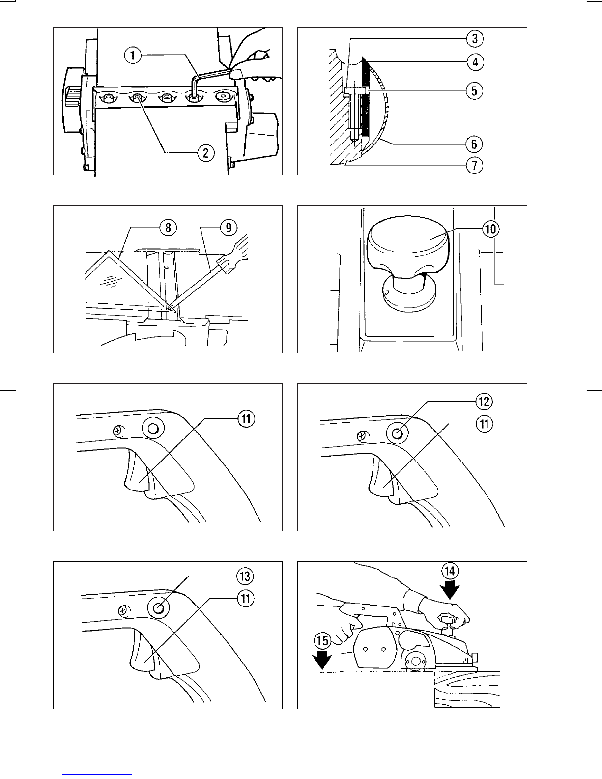
Instellen van schaafdiepte (Fig. 4)
De schaafdiepte is heel eenvoudig in te stellen door
de knop voor op het gereedschap te verdraaien.
Werking van de trekschakelaar
LET OP:
Alvorens de machine op netstroom aan te sluiten,
dient u altijd te controleren of de trekschakelaar
behoorlijk werkt en bij het loslaten naar de ‘‘OFF’’
positie terugkeert.
Voor machines zonder vastzetknop en
ontgrendelknop (Fig. 5)
Om de machine in te schakelen, drukt u gewoon de
trekschakelaar in. Laat de schakelaar los om de
machine uit te schakelen.
Voor machines met een vastzetknop (Fig. 6)
Om de machine in te schakelen, drukt u gewoon de
trekschakelaar in. Laat de schakelaar los om de
machine uit te schakelen. Voor continu gebruik, eerst
de trekschakelaar en dan de vastzetknop indrukken.
Om de machine vanuit de vergrendelde stand te
stoppen, de trekschakelaar helemaal indrukken en
deze dan loslaten.
Voor machines met een ontgrendelknop (Fig. 7)
Een ontgrendelknop is voorzien om te voorkomen dat
de trekschakelaar per toeval wordt ingedrukt. Om de
machine te starten, druk de ontgrendelknop in en druk
dan de trekschakelaar in. Om de machine te stoppen,
de trekschakelaar loslaten.
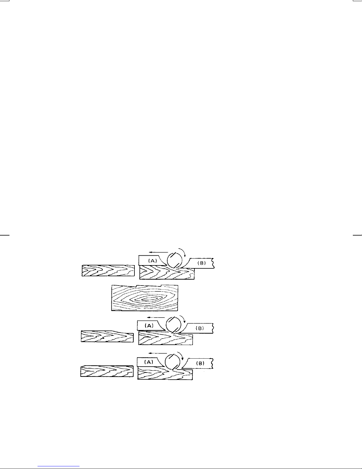
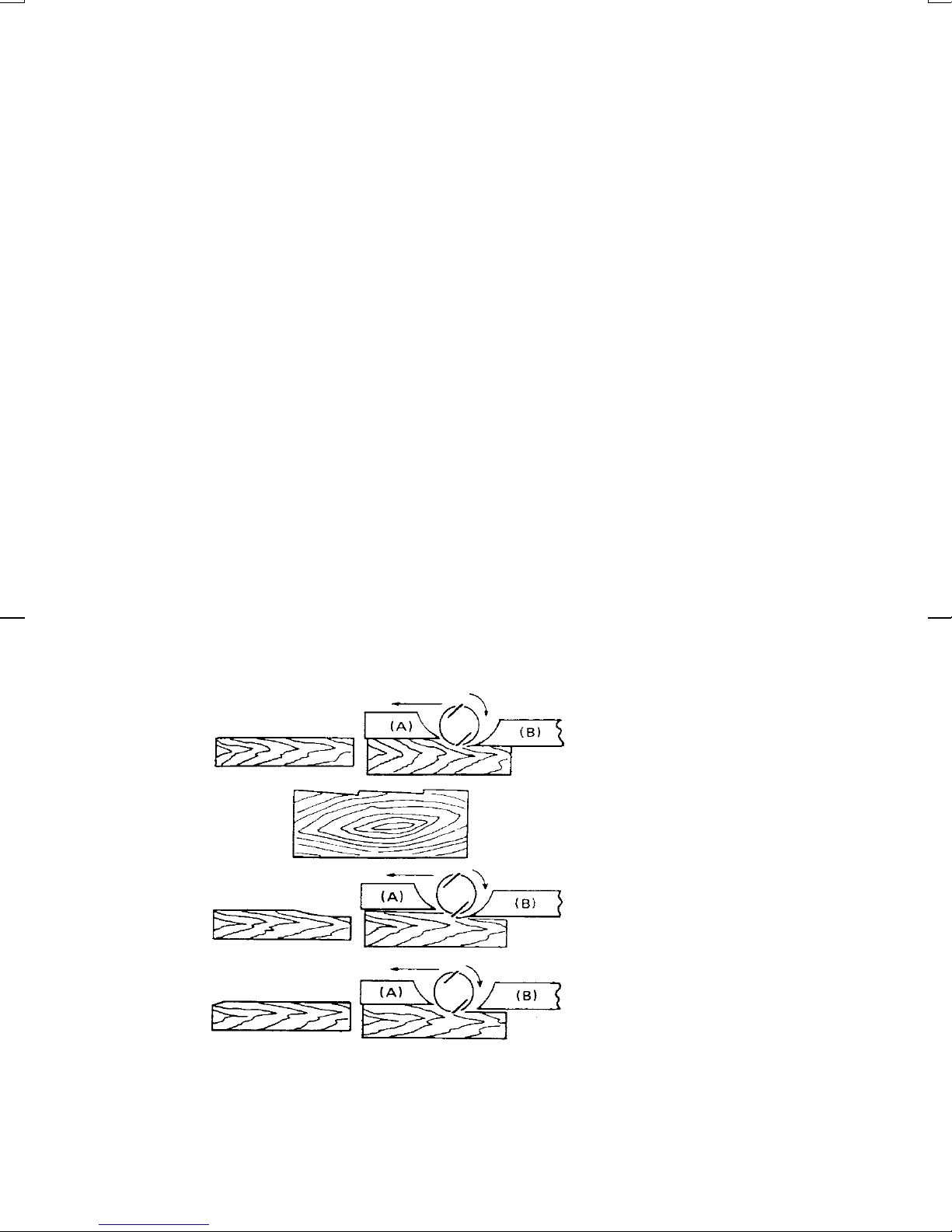
Schaven (Fig. 8)
Leg eerst het voorste zoolvlak plat op het oppervlak
van het werkstuk, zonder dat de messen nog iets
aanraken. Schakel het gereedschap in en wacht
totdat de messen op volle snelheid draaien. Hierna
beweegt u het gereedschap langzaam vooruit. Oefen
druk uit op het voorste gedeelte van het gereedschap
als u begint te schaven en op het achterste gedeelte
als het einde nadert. Het schaven gaat gemakkelijker
als u het werkstuk een beetje schuins houdt, zodat u
schaaft met het gereedschap iets naar beneden
gericht.
De snelheid waarmee u schaaft en de schaaftdiepte
bepalen het resultaat. De snelheid van verspanen zelf
is zodanig dat de spanen nooit klemraken. Voor ruw
schaven kunt u de schaafdiepte vermeerderen, terwijl
voor een goede afwerking de schaafdiepte vermind-
erd moet worden en het gereedschap langzamer
vooruitbewogen dient te worden.
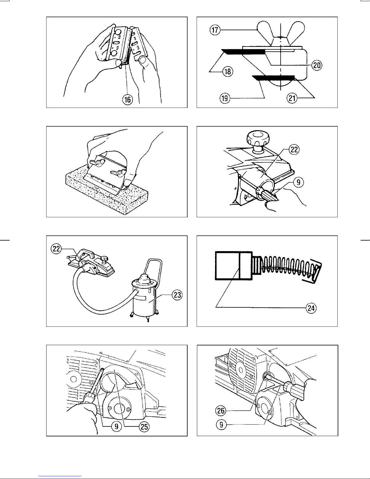
Aanscherpen van de schaafmessen
(Fig. 9, 10 en 11)
Houd uw schaafmessen altijd scherp om de best
mogelijke resultaten te krijgen. Gebruik de slijphouder
om bramen te verwijderen en fijn geslepen randen te
krijgen.
Draai eerst de twee vleugelmoeren op de houder los
en steek messen (A) en (B) erin zodat deze met
zijkanten (C) en (D) in aanraking komen. Draai dan de
twee vleugelmoeren vast.
Dompel de wetsteen voor 2 of 3 minuten in water
alvorens aan te scherpen. Houd de aanscherphouder
zodanig, dat beide messen met de wetsteen in aan-
raking komen voor gelijktijdig aanscherpen onder
dezelfde hoek.
Aansluiten van een stofzuiger
Voor Europese landen en gebieden (Fig. 12 en 13)
Voor stofvrij schaven sluit u een Makita-stofzuiger aan
op uw machine. Monteer de zuigkop (bijgeleverd
onderdeel) op de machine door gebruikmaking van
de bijgeleverde schroeven. Sluit daarna een slang
van de stofzuiger aan op de zuigkop (zie Fig. 13).
Voor andere landen en gebieden
Om een Makita-stofzuiger aan uw machine te beves-
tigen, hebt u een verbindingsstuk en scharnierstuk
(los verkrijgbare accessoires) nodig. Voor het
verbindingsstuk en scharnierstuk dient u een catalo-
gus of vertegenwoordiger van Makita te raadplegen.
ONDERHOUD
LET OP:
Zorg er altijd voor dat de machine is uitgeschakeld en
de stekker uit het stopcontact is verwijderd alvorens
onderhoud aan de machine uit te voeren.
Vervangen van koolborstels
(Fig. 14, 15 en 16)
Vervang de koolborstels wanneer deze tot aan de
limietmarkering zijn versleten. Verwijder eerst de
spaanafvoer en vervang dan de koolborstels. Ver-
vang altijd beide koolsborstels gelijktijdig door gelijk-
soortige koolborstels.
Opdat het gereedschap veilig en betrouwbaar blijft,
dienen alle reparaties, onderhoud of afstellingen te
worden uitgevoerd bij een erkend Makita service
centrum.
1806B (Nl) (’100. 9. 28)
19
Other manuals for 1806B
20
Table of contents
Languages:
Other Makita Planer manuals

Makita
Makita PC1100 User manual

Makita
Makita PC5010C User manual

Makita
Makita 2012NB User manual

Makita
Makita 1806B User manual

Makita
Makita PC1100 User manual

Makita
Makita 1051D User manual

Makita
Makita DKP181 User manual

Makita
Makita 1805N User manual

Makita
Makita 1911B User manual

Makita
Makita DKP140 User manual

Makita
Makita 1900B User manual

Makita
Makita KP0800 User manual

Makita
Makita KP0800 User manual

Makita
Makita KP0810 User manual

Makita
Makita 1911B User manual

Makita
Makita 1002BA Quick start guide

Makita
Makita N1923B User manual

Makita
Makita DKP140 User manual

Makita
Makita 1902 Quick start guide

Makita
Makita KP312 User manual