Makita HR4013C User manual

GB DUST EXTRACTOR ATTACHMENT
FSYSTÈME D’ASPIRATION
DSTAUBABSAUGUNG
IACCESSORIO ESTRATTORE DI POLVERE
NL STOFVANGER
EACCESORIO RECOLECTOR DE POLVO
PCONECTOR COLETOR DE PÓ
DK STØVUDSUGNINGSTILBEHØR
GR ΠΡΟΣΑΡΤΗΜΑ ΕΞΑΓΩΓΕΑ ΣΚΟΝΗΣ
TR TOZ TEMİZLEME ATAŞMANI
SDAMMUTSUGNINGSTILLSATS
NSTØVAVSUG
FIN PÖLYNKERÄIN
LV PUTEKĻU AIZSEGA PAGARINĀJUMS
LT DULKIŲ IŠTRAUKIMO PRIEDAS
EE TOLMUEEMALDUSSEADIS
RUS НАСАДКА ДЛЯ УДАЛЕНИЯ ПЫЛИ
UA НАСАДКА ДЛЯ ПИЛОВИДАЛЕННЯ
PL PRZYSTAWKA DO ODSYSANIA PYŁU
RO ACCESORIU EXTRACTOR DE PRAF
HU PORGYŰJTŐ TOLDALÉK
SK PRÍSLUŠENSTVO ODSÁVAČA PRACHU
CZ NÁSTAVEC ODSAVAČE PRACHU
CS 集尘抽出装置
CT 集塵裝置組件
KR 집진 어태치먼트
ID ALAT TAMBAHAN PENGHISAP DEBU
VI PH TNG B HT BI
TH
PR

2
3
21
4
8
9
7
6
5
1
21
10
3
4
3
2
1
5
6
11
9
6
3
4

3
12
7
8
56

4
English
Intended use
This attachment is intended for reducing blown-away
dust and particles when chiselling or drilling in a ceramic
material such as concrete and mortar.
WARNING: Before installing or removing the
dust extractor attachment, make sure that the tool
is switched off and unplugged. Failure to do so may
cause serious personal injury.
Components (Fig. 1)
1. Dust cover 1 pc.
2. Dust cover extension 2 pcs.
3. Bellows 2 pcs.
4. Joint
(Applicable drill bit diameter: max. 45 mm) 2 pcs.
5. Joint 25 1 pc.
6. Hose Holder 1 pc.
7. Depth gauge (Standard Accessory in tool) 1 pc.
8. Depth gauge extension 1 pc.
9. Holder joint 1 pc.
Assembly (Fig. 2)
1. Unplug the tool.
2. Loosen the side grip (10) on the tool.
3. Insert the rear part of the dust cover (1) between the
groove of the hammer and the belt of the side grip.
4. Tighten the side grip (10) securely by turning the grip
clockwise.
5. Set the suitable bellows (3) or dust cover extension
(2) for your work. When you use bellows, attach
the joint (4) to its top. When you stack two bellows,
connect them with the joint (4).
Connecting vacuum cleaner (Fig. 3)
Use the joint 25 (5), if necessary, to connect the hose
(11) and the dust cover (1).
Fix the hose to the power cord of the tool with the hose
holder (6).
Note:
For battery-powered tools, attach the holder joint (9)
to the tool, and then attach the hose holder (6) to the
holder joint. (Fig. 4)
Using the depth gauge for drilling operation
(Fig. 5)
While pressing the lock button (12), insert the depth
gauge (7) and adjust the depth. Make sure that its
toothed side faces the toothed side of the hex hole
marking.
When using two bellows stacked, set the depth gauge
extension (8). (Fig. 6)
Français
Utilisation prévue
Ce système est prévu pour réduire la quantité de
poussières et de particules libérées par le burinage ou
le perçage de matériaux céramiques comme le béton ou
le mortier.
AVERTISSEMENT : Avant d’installer ou de
démonter le système d’aspiration, assurez-vous que
l’outil est hors tension et débranché. Le non-respect
de cette consigne peut entraîner des blessures graves.
Descriptif (Fig. 1)
1. Capot anti-poussière 1
2. Extension du capot anti-poussière 2
3. Soufets 2
4. Joint (Diamètre du foret : 45 mm max.) 2
5. Joint 25 1
6. Support de tuyau 1
7. Guide de profondeur
(Accessoire standard fourni avec l’outil) 1
8. Extension du guide de profondeur 1
9. Joint du support 1
Montage (Fig. 2)
1. Débranchez l’appareil.
2. Desserrez la poignée latérale (10) de l’outil.
3. Insérez la partie arrière du capot anti-poussière (1)
entre la rainure du marteau et la couronne de la
poignée latérale.
4. Serrez fermement la poignée latérale (10) en la
tournant dans le sens horaire.
5. Selonletypedetravail,installezlessoufets(3) ou
l’extension du capot anti-poussière (2). Lorsque vous
utilisezdessoufets,xezunjoint(4) à l’extrémité
de l’ensemble. Lorsque vous assemblez deux
soufets,raccordez-lesavecunjoint(4).
Raccordement à l’aspirateur (Fig. 3)
Utilisez si nécessaire le joint 25 (5) pour raccorder le
tuyau (11) et le capot anti-poussière (1).
Fixez le tuyau au cordon d’alimentation de l’outil au
moyen du support de tuyau (6).
Note :
Pourlesoutilsfonctionnantsurbatterie,xezlejointdu
support (9)surl’outil,puisxezlesupportdetuyau(6)
sur le joint du support. (Fig. 4)
Utilisation du guide de profondeur pour le
perçage (Fig. 5)
Tout en appuyant sur le bouton de verrouillage (12),
insérez le guide de profondeur (7) et ajustez la
profondeur. Assurez-vous que l’orientation de son côté
denté correspond à celle du repère du trou hexagonal.
Lorsquevousutilisezdeuxsoufetsassemblés,montez
l’extension du guide de profondeur (8). (Fig. 6)

5
Deutsch
Verwendungszweck
Diese Vorrichtung dient dazu, weggeblasenen Staub und
Partikel beim Meißeln oder Bohren in Keramikmaterial,
wie z. B. Beton und Mörtel, aufzufangen.
WARNUNG: Bevor Sie die Staubabsaugung
anbringen oder abnehmen, vergewissern Sie
sich, dass das Werkzeug ausgeschaltet und vom
Stromnetz getrennt ist. Anderenfalls kann es zu
schweren Verletzungen kommen.
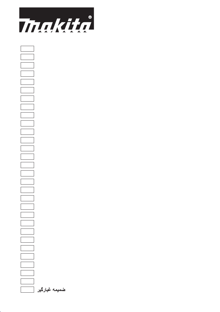
Komponenten (Abb. 1)
1. Staubfänger 1 Stück
2. Staubfängerverlängerung 2 Stück
3. Faltenbalg 2 Stück
4. Absaugstutzen
(Anwendbarer
Bohrerdurchmesser: max. 45 mm) 2 Stück
5. Absaugstutzen 25 1 Stück
6. Schlauchhalter 1 Stück
7. Tiefenanschlag
(Standardzubehör im Werkzeug) 1 Stück
8. Tiefenanschlagverlängerung 1 Stück
9. Halterverbindung 1 Stück
Zusammenbau (Abb. 2)
1. Trennen Sie das Werkzeug vom Stromnetz.
2. Lösen Sie den Seitengriff (10) am Werkzeug.
3. Führen Sie den hinteren Teil des Staubfängers (1)
zwischen die Nut des Hammers und den Gurt des
Seitengriffs ein.
4. Ziehen Sie den Seitengriff (10) durch Drehen des
Griffs im Uhrzeigersinn gut fest.
5. Bringen Sie einen geeigneten Faltenbalg (3) oder
die Staubfängerverlängerung (2) für Ihre Arbeit an.
Wenn Sie einen Faltenbalg verwenden, bringen
Sie den Absaugstutzen (4) an seinem oberen Ende
an. Wenn Sie zwei Faltenbälge zusammensetzen,
verbinden Sie sie mit dem Absaugstutzen (4).
Anschließen eines Staubsaugers (Abb. 3)
Verwenden Sie gegebenenfalls den Absaugstutzen 25
(5), um den Schlauch (11) und den Staubfänger (1) zu
verbinden.
Befestigen Sie den Schlauch mit dem Schlauchhalter (6)
am Netzkabel des Werkzeugs.
Hinweis:
Befestigen Sie bei batteriebetriebenen Werkzeugen die
Halterverbindung (9) am Werkzeug, und befestigen Sie
dann den Schlauchhalter (6) an der Halterverbindung.
(Abb. 4)
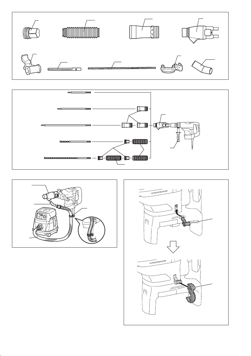
Verwendung des Tiefenanschlags für
Bohrbetrieb (Abb. 5)
Während Sie den Arretierknopf (12) drücken, führen Sie
den Tiefenanschlag (7) ein, und stellen Sie die Tiefe
ein. Vergewissern Sie sich, dass seine gezahnte Seite
auf die gezahnte Seite der Sechskantlochmarkierung
ausgerichtet ist.
Wenn Sie zwei Faltenbälge hintereinander verwenden,
bringen Sie die Tiefenanschlagverlängerung (8) an.
(Abb. 6)
Italiano
Utilizzo presso
Questo accessorio è progettato per ridurre la polvere
eleparticellesofateviadurantelascalpellaturao
la foratura dei materiali in ceramica, come pure del
cemento e malta.
AVVERTIMENTO: Prima di installare o di
rimuovere l’accessorio estrattore di polvere,
accertarsi che l’utensile sia spento e staccato dalla
presa di corrente. In caso contrario, c’è pericolo di un
grave incidente.
Componenti (Fig. 1)
1. Coperchio polvere 1
2. Prolunga coperchio polvere 2
3. Sofetto 2
4. Giunto
(Diametro punta trapano utilizzabile: 45 mm max.) 2
5. Giunto 25 1
6. Supportotuboessibile 1
7. Calibro di profondità
(Accessorio di serie nell’utensile) 1
8. Prolunga calibro di profondità 1
9. Giunto del supporto 1
Montaggio (Fig. 2)
1. Staccare l’utensile dalla presa di corrente.
2. Allentare l’impugnatura laterale (10) sull’utensile.
3. Inserire la parte posteriore del coperchio polvere
(1) tra la scanalatura del martello e la cinghia
dell’impugnatura laterale.
4. Stringere saldamente l’impugnatura laterale (10)
girandola in senso orario.
5. Montareilsofetto(3) o la prolunga coperchio
polvere (2)adattiallavoro.Sesiusailsofetto,
attaccarvi sopra il giunto (4). Se si montano due
sofettiunosopral’altro,collegarliconilgiunto(4).
Collegamento dell’aspiratore (Fig. 3)
Se necessario, usare il giunto 25 (5) per collegare il tubo
essibile(11) e il coperchio polvere (1).
Fissareiltuboessibilealcavodialimentazioneconil
supportotuboessibile(6).
Nota:
Per gli utensili alimentati a batteria, applicare il giunto
del supporto (9) all’utensile, quindi applicare il supporto
tuboessibile(6) al giunto del supporto. (Fig. 4)
Uso del calibro di profondità per l’operazione
di foratura (Fig. 5)
Premendo il bottone di blocco (12), inserire il calibro di
profondità (7) e regolare la profondità. Accertarsi che
il suo lato dentato sia rivolto sul lato dentato del segno
foro esagonale.
Usandoduesofettiunosopral’altro,montarela
prolunga calibro di profondità (8). (Fig. 6)
Other manuals for HR4013C
1
Table of contents
Other Makita Power Tools Accessories manuals

Makita
Makita 194485-1 User manual

Makita
Makita P-54190 User manual

Makita
Makita RBC260 Operating and installation instructions

Makita
Makita UB400MP User guide

Makita
Makita WST05 User manual

Makita
Makita 4301BV Operating and installation instructions

Makita
Makita EM407MP User guide

Makita
Makita UB400MP User guide

Makita
Makita EN422MP User manual