manuals.online logo
Brands
  1. Home
  2. •
  3. Brands
  4. •
  5. Makita
  6. •
  7. Saw
  8. •
  9. Makita 2414EN Manual

Makita 2414EN Manual

Models No.
Description
PRODUCT
CONCEPT AND MAIN APPLICATIONS
Specification
Standard equipment
Note: The standard equipment for the tool shown may vary by country.
P 1/ 9
2414EN
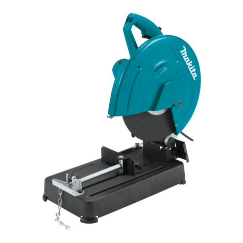
355mm (14") Portable Cut-Off
Dimensions: mm (")
Width (W)
Height (H)
Length (L) 500 (19-3/4)
620 (24-3/8)
280 (11)
355 (14)
25.4 (1)
17.6 (38.7)
3,800
90° 45°
D
H
W115 (4-1/2) x 130 (5-1/8)
102 (4) x 194 (7-5/8)
70 (2-3/4) x 233 (9-1/8)
137 (5-3/8) x 137 (5-3/8)
10 (3/8)
100 (4) x 100 (4)
10 (3/8)
W
H
S S
Power supply cord: m (ft)
No load speed: min.ˉ¹= rpm
Wheel size: mm (")
Diameter
Arbor
Thickness
Capacity: mm (")
Miter angle
Weight according to
EPTA-Procedure 01/2003*1: kg (lbs)
Form of materials
D: Diameter
W: Width
H: Height
S: Side
T: Thickness
T
3 (1/8)
2.5 (8.2)
ø115 (4-1/2) ø115 (4-1/2)
Continuous Rating (W)
Voltage (V) Cycle (Hz) Input Output Max. Output(W)
110
220
230
240
Current (A)
50/60
50/60
50/60
50/60
50/60
15.0
120 15.0
9.6
9.2
8.8
1,650
---
2,400900
2,400900
2,000 1,200 3,300
2,000 1,200 3,300
2,000 1,200 3,300
Socket wrench 17 ............................................... 1
Abrasive cut-off wheel 355 ................................ 1
119 (4-11/16) x 119 (4-11/16) 106 (4-3/16) x 106 (4-3/16)
Model 2414EN has been developed based on current model 2414NB
to comply with the new EU standards (EN61029-2-10: 2010).
The safety cover, safety guard, spark guard and quick vise are redesign
of those of 2414NB.
This product is also available with an upgraded armature gear
for some countries as model 2414ENE.
*1 with Abrasive cut-off wheel 355
Optional accessories
Abrasive cut-off wheel 355
115 (4-1/2) x 103 (4-1/16)
L
W
H
TECHNICAL INFORMATION
H x W
H x W
S x S
T
P 2/ 9
Repair
CAUTION: Repair the machine in accordance with “Instruction manual” or “Safety instructions”.
Fig. 1
Safety cover
Spring holder
Pin 16-113
63
63 M10 Hex bolt Top where Spring holder contacts a little
86
Helical gear 41
Compression spring 45
57
[1] NECESSARY REPAIRING TOOLS
[2] LUBRICATIONS
Code No. Description Use for
1R003 Retaining ring pliers ST-2N removing Pin 16-113
1R269 Bearing extractor removing Ball bearing 6000 from Spindle
Apply the following grease to the portions pointed with triangles to protect parts and product from unusual abrasion.
Item No. Description
Gear housing complete
Base
Ring 17
Punched hole for Pin 16-113 passing
Outside where Safety cover contacts
Lubricant AmountPortion to lubricate
Makita grease N No.1
57 25 g
2 g
a little
a little
86
Surface where 86 Base contacts
Gear room where Helical gear 41 rotates
16
14
16
14 ,
P 3/ 9
Repair
[3] DISASSEMBLY/ASSEMBLY
[3] -1. Armature
DISASSEMBLING
DISASSEMBLING
Armature can be removed as drawn in Fig. 2.
Assemble Armature by reversing the disassembly procedure. (Refer to Fig. 2)
2. Separate Motor housing together with Handle
by unscrewing six M5x50 Pan head screws
and M5x35 Pan Head screw.
ASSEMBLING
M5x35 Pan head screw
Ball bearing
6202DDW
Ball bearing
629LLB
Washer 15
Resin washer
1. Remove Brush holder caps and Carbon
brushes from the machine.
3. Remove Armature from Gear housing.
4. Armature can be disassembled.
M5x50
Pan head screw
( 6 pcs. )
M5x50
Pan head screw
( 6 pcs. )
Viewed from Motor housing side
Important: It is not necessary to remove the other screws.
Fig. 2
1. Remove Safety cover section as drawn in Fig. 3.
[3] -2. Helical gear 41
1. Unscrew M6x10 Thumb screw and open Center cover
together with Safety guide.
And then remove M10x25 Hex bolt, Flange 90 (2pcs.),
Cut-off wheel, O ring 14 and Ring 17 from the machine.
2. Remove Safety cover section (including Safety
guide and Center cover) from Gear housing
by unscrewing four M6x20 Pan head screws.
And then remove the other Ring 17 from Spindle.
Fig. 3
M6x10
Thumb screw
Center cover Safety guide
Safety cover
Ring 17
P 4/ 9
Repair
ASSEMBLING
Assemble by reversing the disassembly procedure. (Refer to Figs. 4 and 3)
Note: 1. Assemble Spindle to Helical gear 41 as drawn in Fig. 5.
2. Do not forget to mount Ring 17 to Spindle when assembling Safety cover section to Gear housing.
(Refer to the right illustration in Fig. 3)
3. Do not forget to mount the other Ring 17 and O ring 14 between Inner and Outer flanges. (Fig. 6)
Fig. 5 Fig. 6
Ring 17Outer flange 90
Inner flange 90
O ring 14
Flat portion of
Helical gear 41
Bearing
setting plate
Flat portion of
Spindle
Press-fit Spindle to Helical gear 41 while aligning
the flat portion of Spindle with the flat portion of
the gear.
[3] DISASSEMBLY/ASSEMBLY
[3] -2. Helical Gear 41 (cont.)
DISASSEMBLING
2. Separate Gear section from Gear housing, and disassemble the removed Gear section as drawn in Fig. 4.
1. Remove Gear section (including
Bearing box, Spindle and Ball
bearings) from Gear housing.
2. Remove Spindle together with Ball
bearing 6000 from Bearing box
with Arbor press.
3. Remove Ball bearing
6000 from Spindle
with 1R269.
Fig. 4
Ball bearing
6000
Gear section
Spindle
Helical gear 41
Bearing box
1R269
P 5/ 9
Repair
[3] DISASSEMBLY/ASSEMBLY
[3] -3. Vise Section
DISASSEMBLING
Refer to Fig. 7.
Fig. 7
Screw guide
M8x30 Pan head
screw (2pcs.)
1. Remove M8x30 Pan head screws (2pcs.)
and Chain from Screw guide.
Vise screw
Vise plate
Shoulder pin
10-16
Retaining ring S-16 Shoulder pin 10-16
Vise plate
5. Separate Vise screw section from Vise plate
by removing Retaining ring S-8.
Hole for removing
Shoulder pin 10-16
Retaining
ring S-8
Screw guide
Vise screw
Vise plate
Retaining ring S-8
Flat washer 8
Note:
Be careful not to lose
two Flat washers 8.
Shoulder pin 10-16
Shoulder pin 10-16
6. Shoulder Pin 10-16 is removed through the hole
for the removing Shoulder pin 10-16.
2. Remove Retaining ring S-16 from Shoulder pin 10-16.
Hole for the removing
Shoulder pin 10-16 Vise plate
Chain
4. Push Vise plate to the hole
for the removing Shoulder
pin 10-16.
3. Turn Vise plate to the position
where Retaining ring S-8 can be
easily removed.
P 6/ 9
2. Remove M6x12 Hex socket
head bolt, Spring washer 6
and M6 Hex nut from the
hole near the hinge.
3. Lift up the motor section until Safety
cover touches Spark guard.
Note: Do not remove Spark guard in this
step because this guard functions as a
stopper for avoiding accidental popping
of Compression spring 45.
4. While holding the base section with your knees, push Spring
holder by both hands toward Spring room of Gear housing.
Spring holder is now removed from M10 Hex bolt.
M6x12 Hex socket
head bolt
Chain
Spring washer 6
(1) Compression spring 45 is removed as drawn in Fig. 9.
M6 Hex nut
Spark guard
Spring
holder
5. Remove Spring holder and Compression
spring 45 from the spring room of Gear
housing.
M10 Hex bolt
Compression
spring 45
Fig. 9
Spring
holder
M10 Hex bolt
Compression
spring 45
Spring holder
Compression
spring 45
Repair
[3] DISASSEMBLY/ASSEMBLY
[3] -3. Vise Section (cont.)
Fig. 8
ASSEMBLING
Assemble by reversing the Disassembly procedure. (Refer to Fig. 7)
Note: Align the ring of Chain to the square projection of Screw guide when securing Chain with M8x30 Pan head screw.
(Fig. 8)
Square projection on Screw guide
M8x30 Pan head screw
Ring of Chain
[3]-4. Base
DISASSEMBLING
1. Secure the motor section
to hook Chain on Hanger
at the rear side of Handle.
P 7/ 9
Repair
[3] DISASSEMBLY/ASSEMBLY
[3] -4. Base (cont.)
DISASSEMBLING
M10x130 Hex bolt
Cup washer 10
(2) Remove Safety cover section as illustrated in Fig. 3.
(3) Unscrew M6x10 Pan head screw and remove Spark guard.
(4) Separate Base section from Motor section as drawn in Fig. 10.
ASSEMBLING
(1) Mount Motor section to Base section. (Refer to Fig. 10)
(2) Assemble Compression spring 45 and Spring holder as drawn in Fig. 11.
Cup washer 10
1. Unscrew M10-17 Hex lock nut,
then remove M10x130 Hex bolt
and 2 pcs. of Cup washer 10.
3. Base section is now separated
from Motor section.
M10-17
Hex lock nut
1R003 Pin 16-113
Fig. 10
M10 Hex bolt
Compression
spring 45
Handle 120
(Vise handle) side
While facing the notch of Spring holder to
Handle 120 (Vise handle) side, assemble
the holder to Compression spring 45.
And keeping the above condition, put
Spring holder onto M10 Hex bolt of Base.
Notch of
Spring holder
Fig. 11
2. Insert 1R003 into Pin 16-113 and open it fully in the pin to grip
its internal surface. And pull out the pin while twisting them.
Handle 120
(Vise handle)
P 8/9
White
Support unit viewed
from Fan side
Noise
suppressor
Line filter
(ø 20-10, 2T)
Line filter
(ø 15-17, 2T)
Power supply cord
Switch
Switch
Choke coil
For 220-240V area
For 110V-127V area
Blue
Brown
Color index of lead wires' sheath
Black
Circuit diagram
Fig. D-1
Support unit viewed
from Fan side
Noise
suppressor
Power supply cord
Wiring in Motor housing
Fig. D-3
Rib A
Switch
Noise suppressor
Rib D
Rib G
Boss
Line filter
Coil Lead wires (black) of Support unit
once into Line filter one by one. And place
Line filter in here in case it is used.
Do not put any Lead wires
under Switch.
Rib C
Rib E
Rib F
Cord clamp
Power supply cord
Space between
Rib A and Rib B
Rib B
Lead wires (black) of Support unit
have to be tightened in Motor housing.
Wiring diagram
P 9/ 9
Fig. D-2
Fix Lead wires (black) of Support
unit with these Lead wire holders.
Support unit has to be put into Motor
housing so that its Lead wires (2 blacks)
can be guided out through the space
between Rib A and Rib B.
Pass Lead wires (black) of Support
unit between Rib E and Rib F.
Noise suppressor has to be put
in the space between Switch
and Grip end in case it is used.
Do not put Lead wires (black) of
Support unit on any Ribs in this place.
Power supply cord has to be fixed so that its
Sheath end comes to between Rib G and Boss.
Pass Lead wires (brown, blue) of
Power supply cord and Lead wires
(2 blacks) of Support unit between
Rib C and Rib D.

Other manuals for 2414EN

4

Other Makita Saw manuals

Makita MLT100N User manual

Makita

Makita MLT100N User manual

Makita 5057KB User manual

Makita

Makita 5057KB User manual

Makita JR1000FT User manual

Makita

Makita JR1000FT User manual

Makita 2712 User manual

Makita

Makita 2712 User manual

Makita LS1440 User manual

Makita

Makita LS1440 User manual

Makita LS0711Z User manual

Makita

Makita LS0711Z User manual

Makita HS6601 User manual

Makita

Makita HS6601 User manual

Makita M5801 User manual

Makita

Makita M5801 User manual

Makita JR1000FT User manual

Makita

Makita JR1000FT User manual

Makita SJ401 User manual

Makita

Makita SJ401 User manual

Makita DLS714 User manual

Makita

Makita DLS714 User manual
Makita MLT100 User manual

Makita

Makita MLT100 User manual

Makita DPB181RFE User manual

Makita

Makita DPB181RFE User manual

Makita 5057KB User manual

Makita

Makita 5057KB User manual

Makita 5201NA Operating and maintenance manual

Makita

Makita 5201NA Operating and maintenance manual

Makita 5603R User manual

Makita

Makita 5603R User manual

Makita 2107F User manual

Makita

Makita 2107F User manual

Makita SP6000 User manual

Makita

Makita SP6000 User manual
Makita 7104L User manual

Makita

Makita 7104L User manual

Makita 2414NB User manual

Makita

Makita 2414NB User manual

Makita XSS03 User manual

Makita

Makita XSS03 User manual

Makita LS1013F User manual

Makita

Makita LS1013F User manual

Makita LS1018 User manual

Makita

Makita LS1018 User manual

Makita 5402NA User manual

Makita

Makita 5402NA User manual

Popular Saw manuals by other brands

DeWalt DWE550 Original instructions

DeWalt

DeWalt DWE550 Original instructions

VONROC RS501DC Original instructions

VONROC

VONROC RS501DC Original instructions

Milwaukee 6375-20- 6376-20 Operator's manual

Milwaukee

Milwaukee 6375-20- 6376-20 Operator's manual

DeWalt DWS727 Original instructions

DeWalt

DeWalt DWS727 Original instructions

Scheppach HBS300 Translation from the original instruction manual

Scheppach

Scheppach HBS300 Translation from the original instruction manual

Alpha tools TKS 800 operating instructions

Alpha tools

Alpha tools TKS 800 operating instructions

PEGAS SRP14-CE Setup & operation manual

PEGAS

PEGAS SRP14-CE Setup & operation manual

Ryobi WS721S user manual

Ryobi

Ryobi WS721S user manual

QEP 83200 owner's manual

QEP

QEP 83200 owner's manual

Femi TR-090 Assembly and operating manual

Femi

Femi TR-090 Assembly and operating manual

Bosch GKS 36 V-LI Original instructions

Bosch

Bosch GKS 36 V-LI Original instructions

stayer SC250W operating instructions

stayer

stayer SC250W operating instructions

JML exakt EC310-AS instructions

JML

JML exakt EC310-AS instructions

Schwamborn FBS P operating instructions

Schwamborn

Schwamborn FBS P operating instructions

Extol Industrial SHARE 20V user manual

Extol Industrial

Extol Industrial SHARE 20V user manual

Lumag STM350-800 Operator's manual

Lumag

Lumag STM350-800 Operator's manual

Parkside 339157 1910 instructions

Parkside

Parkside 339157 1910 instructions

AGP CS320 Original instructions

AGP

AGP CS320 Original instructions

manuals.online logo
manuals.online logoBrands
  • About & Mission
  • Contact us
  • Privacy Policy
  • Terms and Conditions

Copyright 2025 Manuals.Online. All Rights Reserved.