4ENGLISH
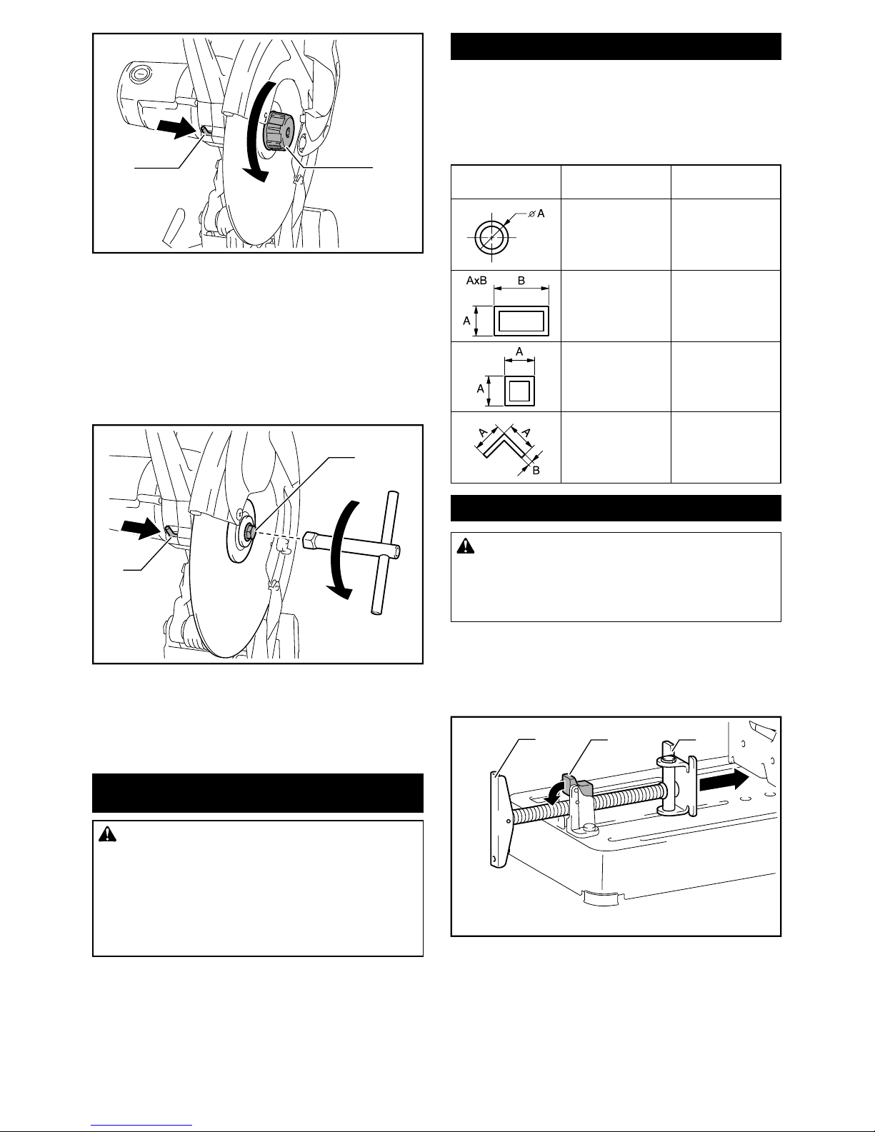
6. The outside diameter and the thickness of your
accessory must be within the capacity rating
of your power tool. Incorrectly sized accessories
cannot be adequately guarded or controlled.
7.
match the mounting hardware of the power tool
will run out of balance, vibrate excessively and
may cause loss of control.
8. Do not use damaged wheels. Before each use,
inspect the wheels for chips and cracks. If the
power tool or wheel is dropped, inspect for
damage or install an undamaged wheel. After
inspecting and installing the wheel, position
yourself and bystanders away from the plane
of the rotating wheel and run the power tool
at maximum no load speed for one minute.
Damaged wheels will normally break apart during
this test time.
9.
Depending on application, use face shield,
safety goggles or safety glasses. As appro-
priate, wear dust mask, hearing protectors,
The
debris generated by various operations. The dust
exposure to high intensity noise may cause hear-
ing loss.
10. Keep bystanders a safe distance away from
work area. Anyone entering the work area
Fragments of workpiece or of a broken wheel may
of operation.
11. Position the cord clear of the spinning acces-
sory. If you lose control, the cord may be cut or
snagged and your hand or arm may be pulled into
the spinning wheel.
12. The
motor’s fan can draw the dust inside the housing
and excessive accumulation of powdered metal
may cause electrical hazards.
13.
materials. Do not operate the power tool while
placed on a combustible surface such as
wood. Sparks could ignite these materials.
14. Do not use accessories that require liquid
coolants. Using water or other liquid coolants
may result in electrocution or shock.
Kickback and related warnings
Kickback is a sudden reaction to a pinched or snagged
stalling of the rotating wheel which in turn causes the
uncontrolled cutting unit to be forced upwards toward
the operator.
For example, if an abrasive wheel is snagged or
pinched by the workpiece, the edge of the wheel that
is entering into the pinch point can dig into the surface
of the material causing the wheel to climb out or kick
out. Abrasive wheels may also break under these
conditions.
Kickback is the result of power tool misuse and/or
incorrect operating procedures or conditions and can be
avoided by taking proper precautions as given below.
1.
position your body and arm to allow you to
resist kickback forces. The operator can control
upward kickback forces, if proper precautions are
taken.
2. Do not position your body in line with the
rotating wheel. If kickback occurs, it will propel
the cutting unit upwards toward the operator.
3.
segmented diamond wheel with a peripheral
gap greater than 10 mm or toothed saw blade.
Such blades create frequent kickback and loss of
control.
4.
depth of cut. Overstressing the wheel increases
the loading and susceptibility to twisting or binding
of the wheel in the cut and the possibility of kick-
back or wheel breakage.
5. When the wheel is binding or when interrupt-
ing a cut for any reason, switch off the power
tool and hold the cutting unit motionless until
the wheel is in motion otherwise kickback may
occur. Investigate and take corrective action to
eliminate the cause of wheel binding.
6. Do not restart the cutting operation in the
workpiece. Let the wheel reach full speed and
carefully re-enter the cut. The wheel may bind,
walk up or kickback if the power tool is restarted in
the workpiece.
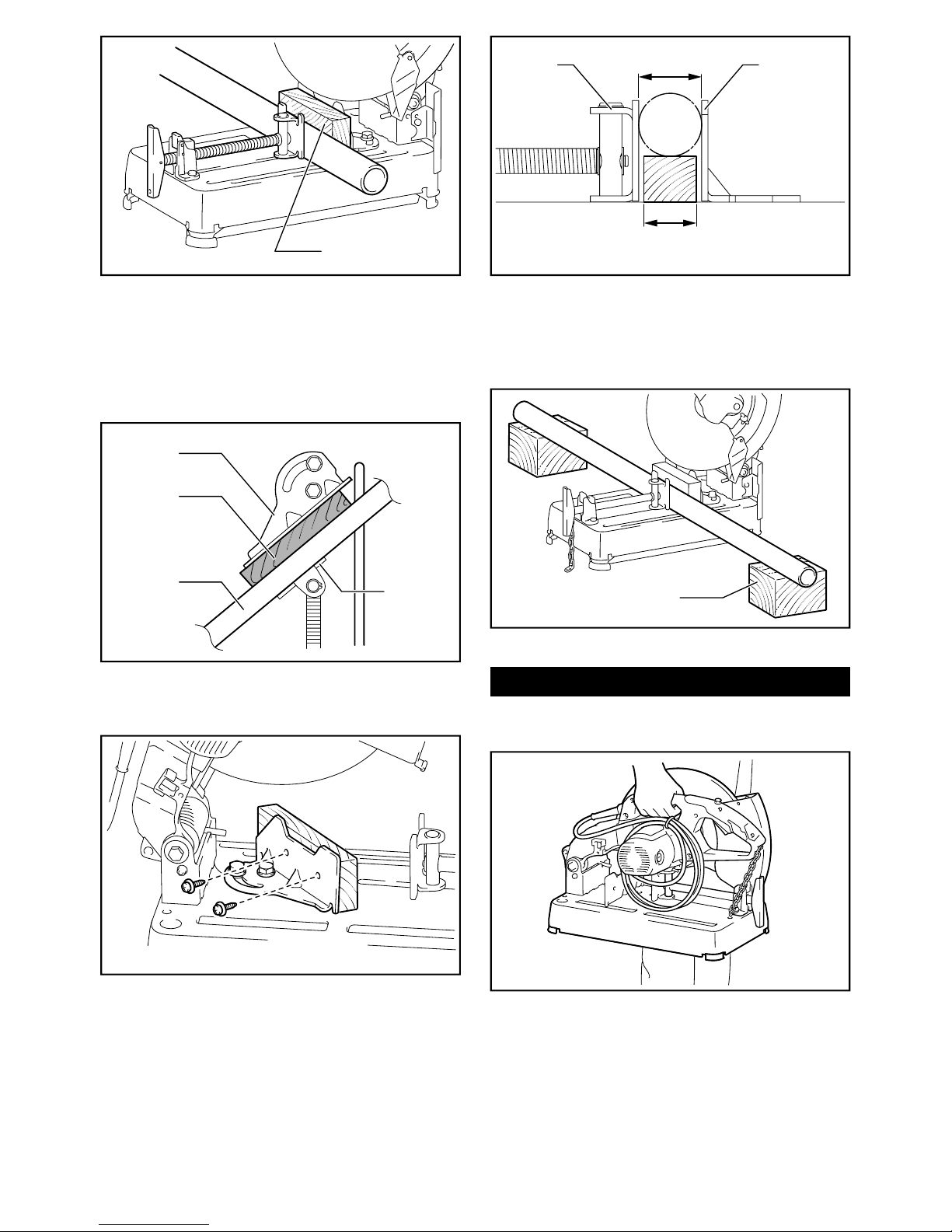
7.
the risk of wheel pinching and kickback. Large
workpieces tend to sag under their own weight.
Supports must be placed under the workpiece
near the line of cut and near the edge of the work-
piece on both sides of the wheel.
Additional safety warnings
1.
materials.
2.
work when practical. It's safer than using your
hand and it frees both hands to operate tool.
3. Secure the wheel carefully.
4.
(especially the installing surface) or bolt, or
the wheel itself might break.
5. Keep guards in place and in working order.
6.
7. Keep hands away from rotating parts.
8. Make sure the wheel is not contacting the
work-piece before the switch is turned on.
9.
-
lation or a poorly balanced wheel.