Makita 2703 User manual

With Electric Brake
210 mm (8-1/4”)
MODEL 2702X1
MODEL 2702
255 mm (10”)
MODEL 2703X1
MODEL 2703
Table Saw
www.makita.com
INSTRUCTION MANUAL
DOUBLE
INSULATION
WARNING: For your personal safety, READ and UNDERSTAND before using.
SAVE THESE INSTRUCTIONS FOR FUTURE REFERENCE.

2
MODEL Arbor
hole
Blade
diameter
Cutting capacities
90°45°
Table size
(W x L)
No load speed
(RPM) Dimensions
(L x W x H)
Maximum dado
capacity Net
weight
18kg
(40 lbs)
4,600/min
560mm x
686mm x
458mm
(22" x 27" x 18")
686mm
x
560mm
(27" x 22")
2702X1
2702
2703X1
2703
5/8" 13 mm (1/2")
210mm
(8-1/4") 68mm
(2-11/16") 47mm
(1-3/4")
255mm
(10") 91mm
(3-9/16") 63mm
(2-1/2")
SPECIFICATIONS
• Manufacturer reserves the right to change specifications without notice.
• Note: Specifications may differ from country to country.

3
9. USE RIGHT TOOL.
Don’t force tool or attachment to do a job
for which it was not designed; for example,
don’t use circular saw for cutting tree limbs
or logs.
10. WEAR PROPER APPAREL.
Wear no loose clothing, gloves, neckties,
rings, bracelets, or other jewelry which
may get caught in moving parts. Nonslip
footwear is recommended.Wear protective
hair covering to contain long hair.
11. ALWAYS USE SAFETY GLASSES.
Also use face or dust mask if cutting oper-
ation is dusty. Everyday eyeglasses only
have impact resistant lenses, they are
NOT safety glasses.
12. SECURE WORK.
Use clamps or a vise to hold work when
practical. It’s safer than using your hand
and it frees both hands to operate tool.
13. DON’T OVERREACH.
Keep proper footing and balance at all
times.
14. MAINTAIN TOOLS WITH CARE.
Keep tools sharp and clean for best and
safest performance. Follow instructions for
lubricating and changing accessories.
15. DISCONNECT TOOLS before
servicing; when changing accessories
such as blades, bits, cutters, and the like.
1. KNOW YOUR POWER TOOL.
Read the owner’s manual carefully. Learn
the tool’s applications and limitations, as
well as the specific potential hazards
peculiar to it.
2. KEEP GUARDS IN PLACE and in work-
ing order.
3. REMOVE ADJUSTING KEYS AND
WRENCHES.
Form habit of checking to see that keys
and adjusting wrenches are removed from
tool before turning it on.
4. KEEP WORK AREA CLEAN.
Cluttered areas and benches invite acci-
dents.
5. DON’T USE IN DANGEROUS
ENVIRONMENT.
Don’t use power tools in damp or wet loca-
tions, or expose them to rain. Keep work
area well lighted. Don’t use tool in pres-
ence of flammable liquids or gases.
6. KEEP CHILDREN AWAY.
All visitors should be kept safe distance
from work area.
7. MAKE WORKSHOP CHILD PROOF
with padlocks, master switches, or by
removing starter keys.
8. DON’T FORCE TOOL.
It will do the job better and safer at the rate
for which it was designed.
For Your Own Safety Read Instruction Manual
Before Operating Table Saw
Save it for future reference
GENERAL SAFETY PRECAUTIONS
(For All Tools)

4
16. REDUCE THE RISK OF
UNINTENTIONAL STARTING.
Make sure switch is in off position before
plugging in.
17. USE RECOMMENDED ACCES-
SORIES.
Consult the owner’s manual for recom-
mended accessories. The use of improper
accessories may cause risk of injury to
persons.
18. NEVER STAND ON TOOL.
Serious injury could occur if the tool is
tipped or if the cutting tool is accidentally
contacted.
19. CHECK DAMAGED PARTS.
Before further use of the tool, a guard or
other part that is damaged should be care-
fully checked to determine that it will oper-
ate properly and perform its intended func-
tion - check for alignment of moving parts,
binding of moving parts, breakage of
parts, mounting, and any other conditions
that may affect its operation. A guard or
other part that is damaged should be prop-
erly repaired or replaced.
20. DIRECTION OF FEED.
Feed work into a blade or cutter against
the direction of rotation of the blade or cut-
ter only.
EXTENSION CORDS.
Make sure your extension cord is in good condition. When using an extension cord, be
sure to use one heavy enough to carry the current your product will draw. An undersized
cord will cause a drop in line voltage resulting in loss of power and overheating. Table 1
shows the correct size to use depending on cord length and nameplate ampere rating. If
in doubt, use the next heavier gage. The smaller the gage number, the heavier the cord.
21. NEVER LEAVE TOOL RUNNING
UNATTENDED. TURN POWER OFF.
Don’t leave tool until it comes to a com-
plete stop.
22. When servicing use only identical
replacement parts.
23. POLARIZED PLUGS.
To reduce the risk of electric shock, this
equipment has a polarized plug (one blade
is wider than the other). This plug will fit in
a polarized outlet only one way. If the plug
does not fit fully in the outlet, reverse the
plug. If it still does not fit, contact a quali-
fied electrician to install the proper outlet.
Do not change the plug in any way.
VOLTAGE WARNING:
Before connecting the tool to a power
source (receptacle, outlet, etc.) be sure
the voltage supplied is the same as that
specified on the nameplate of the tool. A
power source with voltage greater than
that specified for the tool can result in
SERIOUS INJURY to the user - as well as
damage to the tool. If in doubt, DO NOT
PLUG IN THE TOOL. Using a power
source with voltage less than the name-
plate rating is harmful to the motor.
Ampere Rating
More than Not more than
Volts
120 V 25 ft.
18
18
16
14
50 ft.
16
16
16
12
100 ft.
16
14
14
150 ft.
14
12
12
0
6
10
12
6
10
12
16
Total length of cord in feet
AWG
Not Recommended
Table 1. Minimum gage for cord

5
1. Wear eye protection.
2. Don’t use the tool in presence of flam-
mable liquids or gases.
3. NEVER use the tool with an abrasive
cut-off wheel installed.
4. Check the blade carefully for cracks or
damage before operation. Replace
cracked
or damaged blade immediately.
5. Clean the spindle, flanges (especially
the installing surface) and hex nut before
installing the blade. Poor installation may
cause vibration/wobbling or slippage of
the blade.
6.
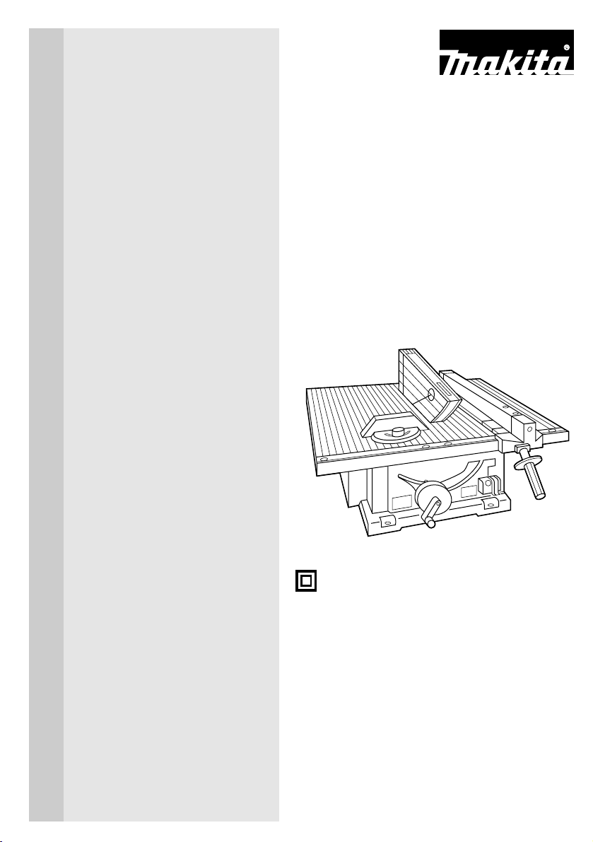
Use saw-blade guard and spreader for
every operation for which it can be used,
including all through sawing operations.
Always assemble and install the blade guard
following the step by step instructions out-
lined in this manual. Through sawing
opera-
tions are those in which the blade cuts
completely through the workpiece as in
ripping or cross cutting. NEVER use the
tool with a faulty blade guard or secure the
blade guard with a rope, string, etc. Any
irregular operation of the blade guard
should be corrected immediately.
7. Immediately reattach the guard and
spreader after completing an operation
which
requires removal of the guard.
8. Do not cut metals such as nails and
screws.Inspect for and remove all nails,
screws and other foreign matter from the
workpiece before operation.
9. Remove wrenches, cut-off pieces, etc.
from the table before the switch is turned on.
10. NEVER wear gloves during operation.
11. Keep hands out of the line of the saw
blade.
12. NEVER stand or permit anyone else to
stand in line with the path of the saw
blade.
13. Make sure the blade is not contacting
the spreader or workpiece before the
switch is turned on.
14. Before cutting an actual workpiece, let
the tool run for a while. Watch for vibration
or wobbling that could indicate poor instal-
lation or a poorly balanced blade.
15. NEVER make any adjustments while
tool is running. Disconnect tool before
making any adjustments.
16. Use a push stick when required. Push
sticks MUST be used for ripping narrow
workpieces to keep your hands and fingers
well away from the blade.
17.
Pay particular attention to instructions
for
reducing risk of KICKBACK. KICKBACK
is a sud-
den reaction to a pinched, bound or misaligned
saw blade. KICKBACK causes the ejection of
the workpiece from the tool back towards the
operator. KICKBACKS CAN LEAD TO SERI-
OUS PERSONAL INJURY. Avoid KICKBACKS
by keeping the blade sharp, by keeping the rip
fence parallel to the blade, by keeping the
spreader, antikickback pawls and blade guard
in place and operating properly, by not releas-
ing the workpiece until you have pushed it all
the way past
the blade, and by not ripping a
workpiece
that is twisted or warped or does not
have
a straight edge to guide along the
fence.
ADDITIONAL SAFETY RULES
DO NOT let comfort or familiarity with product (gained from repeated use) replace strict
adherence to table saw safety rules. If you use this tool unsafely or incorrectly, you can
suffer serious personal injury.

6
18.
Do not perform any operation freehand.
Freehand means using your hands to sup-
port or guide the workpiece, in lieu of a rip
fence or miter gauge.
19. NEVER reach around or over saw
blade. NEVER reach for a workpiece until
the saw blade has completely stopped.
20. Avoid abrupt, fast feeding. Feed as
slowly as possible when cutting hard
work-
pieces. Do not bend or twist workpiece
while
feeding. If you stall or jam the blade in the
workpiece, turn the tool off immediately.
Unplug the tool. Then clear the jam.
21. NEVER remove cut-off pieces near the
blade or touch the blade guard while the
blade is running.
22. Knock out any loose knots from work-
piece BEFORE beginning to cut.
23. Don’t abuse cord. Never yank cord to
disconnect from receptacle. Keep cord
away from heat, oil, water and sharp
edges.
24. Some material contains chemicals
which may be toxic. Take caution to pre-
vent working dust inhalation and skin con-
tact. Follow material supplier safety data.
25. The guard can be lifted during work-
piece setup and for ease of cleaning.
Always make sure that guard hood is
down and flat against sawtable before
plugging in the tool.
SAVE THESE INSTRUCTIONS.
WARNING:
MISUSE or failure to follow the safety rules stated in this instruction manual may cause
serious personal injury.

The tool is shipped from the factory with the saw blade
and blade guard not in the installed condition. Assemble
as follows:
CAUTION:
•Always unplug the tool before assembly.
Installing saw blade
Remove the table insert on the table. Hold the outer
flange with the offset wrench and loosen the hex nut
counterclockwise with the wrench. Then remove the
outer flange.
Assemble the inner flange, blade, outer flange and hex
nut onto the arbor, making sure that the teeth of the
blade are pointing down at the front of the table. Always
install the hex nut with its recessed side facing the outer
flange.
CAUTION:
•Keep the flange surface clean of dirt or other adhering
matter; it could cause blade slippage. Be sure that the
blade is installed so that the teeth are aligned in the cut-
ting (turning) direction.
To secure the blade in place, hold the outer flange with
the offset wrench, then tighten the hex nut clockwise
with the wrench. BE SURE TO TIGHTEN THE HEX
NUT SECURELY.
CAUTION:
•Be sure to hold the hex nut carefully with the wrench.
If your grip should slip, the wrench may come off the
hex nut, and your hand could strike the sharp blade
edges.
7
132
1
4
23
1. Wrench
2. Offset Wrench
3. Hex nut
ASSEMBLY
1. Outer flange
2. Hex nut
3. Inner flange
4. Saw blade
12
1. Wrench
2. Offset Wrench

8
Installing blade guard
CAUTION:
•Before installing the blade guard, adjust the depth of
cut to its maximum elevation. Insert the spreader
between the blade guard mounting portion (stay) and
the pressure plate.
Tighten the hex bolts (A) with the offset wrench. The
spreader installing location is factory-adjusted so that
the blade and spreader will be in a straight line.
However, if they are not in a straight line, loosen the
hex bolts (B) and adjust the blade guard mounting por-
tion (stay) so that the spreader is aligned directly
behind the blade. Then tighten the hex bolts (B) to
secure the stay.
CAUTION:
•Always grasp the striped portion of the offset wrench
when tightening the hex bolts. If you tighten the hex
bolts while grasping the offset wrench further than the
striped portion, the hex bolts may be damaged and/or
an injury to your hand may result.
•If the blade and spreader are not aligned properly, a
dangerous pinching condition may result during opera-
tion. Make sure they are properly aligned. You could
suffer serious personal injury while using the tool with-
out a properly aligned spreader.
•NEVER make any adjustments while tool is running.
Disconnect the tool before making any adjustments.
There must be a clearance of about 4 - 5 mm (5/32”-
13/64”) between the spreader and the blade teeth.
Adjust the spreader accordingly and tighten the hex
bolts (A) securely. Attach the table insert on the table,
then check to see that the blade guard works smoothly
before cutting.
2
1
4
3
1
3
4
57
62
1. Blade guard
2. Spreader
3. Antikickback pawl
4. Pressure plate
1. These two clearances
should be equal
2. Blade guard portion
3. Blade
4. Spreader
5. Pressure plate
6. Hex bolts(A)
7. Hex bolts(B)
4 - 5 mm
(5/32" - 13/64")
12
1. Spreader
2. Blade guard

9
Positioning table saw
Locate the table saw in a well lit and level area where
you can maintain good footing and balance. It should
be installed in an area that leaves enough room to easi-
ly handle the size of your workpieces. The table saw
should be secured with four screws or bolts to the work
bench or table saw stand using the holes provided in
the bottom of the table saw. When securing the table
saw on the work bench, make sure that there is an
opening in the top of the work bench the same size as
the opening in the bottom of the table saw so the saw-
dust can drop through.
If during operation there is any tendency for the table
saw to tip over, slide or move, the work bench or table
saw stand should be secured to the floor.
NOTE:Table saw stand
•Models 2702X1 and 2703X1 are standard-equipped
with a table saw stand.
Storing accessories
The miter gauge and wrenches can be stored on the
left side of the base and the rip fence can be stored at
the rear of the base.
1
1. Miter gauge
1. Hole diameter 8 mm (5/16”)
1. 6 mm (1/4”) Std. washer
2. No. 10 wood screw 40 mm (1-1/2”)
min. length
1. 6 mm (1/4”) Std. washer
2. 6 mm (1/4”) Machine bolt & nut
tighten securely
1
1. Rip fence
459 mm
(18-1/16”)
1
334 mm
(13-1/8”)
25 mm (1”)
1
2
1
2

10
Adjusting depth of cut
The depth of cut may be adjusted by turning the han-
dle. Turn the handle clockwise to raise the blade or
counterclockwise to lower it.
NOTE:
•Use a shallow depth setting when cutting thin materi-
als in order to obtain a cleaner cut.
Adjusting bevel angle
Loosen the lock lever counterclockwise and turn the
handwheel until the desired angle (0°- 45°) is obtained.
The bevel angle is indicated by the arrow pointer.
After obtaining the desired angle, tighten the lock lever
clockwise to secure the adjustment.
CAUTION:
•After adjusting the bevel, be sure to tighten the lock
lever securely.
Adjusting positive stops
The tool is equipped with positive stops at 90°and 45°
to the table surface. To check and adjust the positive
stops, proceed as follows:
Move the handwheel as far as possible by turning it.
Place a triangular rule on the table and check to see if
the blade is at 90°or 45°to the table surface. If the
blade is at an angle shown in Fig. A, turn the adjusting
screws clockwise; if it is at an angle shown in Fig. B,
turn the adjusting screws counterclockwise to adjust
the positive stops.
1
1. Handle
1. Lock lever
2. Handwheel
3. Arrow pointer
1
23
12
90°
(A)
(B)
45°
90°45°
1. 90°adjusting screw
2. 45°adjusting screw

After adjusting the positive stops, set the blade at 90°to
the table surface. Then adjust the arrow pointer so that
its right edge is aligned to the 0°graduation.
Installing and adjusting rip fence
Raise the grip of the rip fence. Install the rip fence on
the table so that the fence holder engages with the
guide rail. The rip fence can be secured by lowering the
grip.
To check to be sure that the rip fence is parallel with the
blade, secure the rip fence 2 - 3 mm (5/64”- 1/8”) from
the blade. Raise the blade up to maximum elevation.
Mark one of the blade teeth with a crayon. Measure the
distance (A) and (B) between the rip fence and blade.
Take both measurements using the tooth marked with
the crayon.These two measurements should be identi-
cal. If the rip fence is not parallel with the blade, pro-
ceed as follows:
1. Turn the adjusting nut counterclockwise a couple of
turns.
2. Loosen the two hex bolts on the rip fence with the
wrench provided.
3. Adjust the rip fence until it becomes parallel with the
blade.
4. Lower the grip to secure the rip fence.
5. Tighten the two hex bolts on the rip fence.
1
1
23
A
B
1
1
2
3
11
1. Arrow pointer
1. Scale
1. Hex bolts
2. Adjusting nut
3. Grip
1. Fence holder
2. Guide rail
3. Grip

12
CAUTION:
•Always grasp the striped portion of the wrench when
tightening the hex bolts. If you tighten the hex bolts
while grasping the wrench further than the striped por-
tion, the hex bolts may be damaged and/or an injury
to your hand may result.
6. With the grip of the rip fence lowered, turn the adjust-
ing nut clockwise to secure the rear end of the rip
fence. Do not turn the adjusting nut clockwise exces-
sively. You may have some difficulty adjusting the rip
fence parallel with the saw blade when repositioning
the rip fence.
CAUTION:
Be sure to adjust the rip fence so that it is parallel with the
blade, or a dangerous kickback condition may occur.
Bring the rip fence up flush against the side of the
blade. Make sure that the arrow pointer on the fence
holder points to the 0 graduation. If the arrow pointer
does not point to the 0 graduation, loosen the screw on
the scale plate and adjust the scale plate.
Switch action
This tool is equipped with a special type of switch to
prevent unintentional starting. To start the tool, first
depress the switch lever.While keeping it depressed,
pull its lower portion toward you. To stop the tool, press
the lower portion of the switch lever.
1. Switch lever
2. Key
1
2
34
1
2
1. Screw
2. Fence holder
3. Scale plate
4. Arrow mark

When operating the switch lever, it is convenient to
view it through the window area in the table.
CAUTION:
•When not using the tool, remove the key and store it
in a secure place. This prevents unauthorized opera-
tion.
•Before plugging in the tool, always check to see that
the switch lever actuates properly and returns to the
“OFF”position.
•Do not pull the switch lever hard without the key. This
can cause breakage of the switch.
CAUTION:
•Always use “work helpers”such as push sticks and
push blocks when there is a danger that your hands or
fingers will come close to the blade.
•Always hold the workpiece firmly with the table and
the rip fence or miter gauge. Do not bend or twist it
while feeding. If the workpiece is bent or twisted, dan-
gerous kickbacks may occur.
•NEVER withdraw the workpiece while the blade is run-
ning. If you must withdraw the workpiece before com-
pleting a cut, first switch the tool off while holding the
workpiece firmly. Wait until the blade has come to a
complete stop before withdrawing the workpiece.
Failure to do so may cause dangerous kickbacks.
•NEVER remove cut-off material while the blade is run-
ning.
•NEVER place your hands or fingers in the path of the
saw blade. Be especially careful with bevel cuts.
•Always secure the rip fence firmly, or dangerous kick-
backs may occur.
•Always use “work helpers”such as push sticks and
push blocks when cutting small or narrow workpieces,
or when the dado head is hidden from view while cut-
ting.
Work helpers
Push sticks, push blocks or auxiliary fence are types of
“work helpers”. Use them to make safe, sure cuts with-
out the need for the operator to contact the blade with
any part of the body.
13
OPERATION

14
Push stick
A push stick can be easily made from a piece of ply-
wood 19 mm (3/4”) to 25 mm (1”) thick.
Cut out the hatched area on the stick and smooth
edges with a file. (H) dimension should be less than
12.7 mm (1/2”) so as to be thinner than the workpiece.
Push block
Use a 19 mm (3/4”) piece of plywood.
Handle should be in center of plywood piece. Fasten
with glue and wood screws as shown. Small piece 9.5
mm x 8 mm x 50 mm (3/8”x 5/16”x 2”) of wood must
always be glued to plywood to keep the blade from
dulling if the operator cuts into push block by mistake.
(Never use nails in push block.)
Auxiliary fence
Make auxiliary fence from 9.5 mm (3/8”) and 19 mm
(3/4”) plywood pieces.
300 mm (12”)120 mm
(4-3/4”)
1
6 mm (1/4”)50mm (2”)
130 mm
(5”)
2
50 mm
(2”)
130 mm
(5”)
3
50 mm (2”)8 mm (5/16”)
4
9.5 mm (3/8”)100 mm (4”)
300 mm (12”)
(H) 9.5 mm
(3/8”)
130 mm (5”)
75 mm (3”)
9.5 mm (3/8”)50 mm
(2”)
19 mm
(3/4”)
40 mm
(1-1/2”)50mm (2”)
380 mm (15”)
1. Face/edge parallel
2. Handle
3. Wood screw
4. Glue together
9.5 mm
(3/8”)
120 mm
(4-3/4”)
1
19 mm
(3/4”)
40 mm
(1-1/2”)
460 mm (18”)140 mm
(5-1/2”)
Fasten with glue and wood screws.
1. Face/edge parallel

Wood facing (rip fence)
A wood facing should be used for operations when the
blade comes close to the rip fence. Wood facing for the rip
fence should be the same size as the rip fence. Make sure
the bottom of facing is flush with the table surface.
Crosscutting
CAUTION:
•When making a crosscut, remove the rip fence from
the table.
•When cutting long or large workpieces, always provide
adequate support to the sides of the table. The sup-
port should be at the same height as the table.
•Always keep hands away from path of blade.
Miter gauge
Use the miter gauge for the 4 types of cutting shown in
the figure.
CAUTION:
•Secure the knob on the miter gauge carefully.
•Avoid creep of workpiece and gauge by firm workhold-
ing arrangement, especially when cutting at an angle.
•NEVER hold or grasp the intended “cut-off”portion of
the workpiece.
Use of miter gauge
Slide the miter gauge into the thick grooves in the table.
Loosen the knob on the gauge and align to desired
angle (0°to 60°). Bring stock flush up against fence and
feed gently forward into the blade.
15
1. No. 10 wood screws (long enough
to penetrate halfway into facing)
1
12
34
1. CROSS CUTTING
2. MITERING
3. BEVEL CUTTING
4. COMPOUND MITERING
(ANGLES)
3
2
1
1. Groove
2. Miter gauge
3. Knob

16
Auxiliary wood facing (miter gauge)
To prevent a long board from wobbling, fit the miter
gauge with an auxiliary fence board. Fasten with
bolts/nuts after drilling holes, but fasteners must not
protrude from the face board.
Ripping
CAUTION:
•When ripping, remove the miter gauge from the table.
•When cutting long or large workpieces, always provide
adequate support behind the table. DO NOT allow a
long board to move or shift on the table. This will
cause the blade to bind and increase the possibility of
kickback and personal injury. The support should be at
the same height as the table.
Before operating the table saw, check to be sure that
the antikickback pawls operate properly. Turn the tool
off and unplug it. Feed the workpiece under the blade
guard and along both sides of the blade to simulate cut-
ting. Try to withdraw the workpiece on each side by
pulling it toward you. The antikickback pawls should
grab the workpiece and prevent it from moving back
toward the operator. Always keep the antikickback
pawls sharp so they will operate properly. Keep them
sharp by using a round-shaped file to maintain the origi-
nal shape of the pawls.
1. Adjust the depth of cut a bit higher than the thickness
of the workpiece.
2. Position the rip fence to the desired width of rip and
lock in place by lowering the grip. Before ripping,
make sure the rear end of the rip fence is secured
firmly. If it is not secured enough, follow the proce-
dures in “Installing and adjusting rip fence”described
on page 11 and 12.

3. Turn the tool on and gently feed the workpiece into
the blade along with the rip fence.
(1) When the width of rip is 150 mm (6”) and wider,
carefully use your right hand to feed the work-
piece. Use your left hand to hold the workpiece
in position against the rip fence.
(2) When the width of rip is 65 mm - 150 mm (2-1/2”
- 6”) wide, use the push stick to feed the work-
piece.
(3) When the width of rip is narrower than 65 mm
(2-1/2”), the push stick cannot be used because
the push stick will strike the blade guard. Use the
auxiliary fence and push block.
Attach the auxiliary fence to the rip fence with
two “C”clamps.
Feed the workpiece by hand until the end is about
25 mm (1”) from the front edge of the table. Continue
to feed using the push block on the top of the auxiliary
fence until the cut is complete.
17
1
1. Push stick
1
1. Auxiliary fence
1. Push block
2. Auxiliary fence
1
2

CAUTION:
•Always be sure that the tool is switched off and
unplugged before attempting to perform inspection or
maintenance.
Cleaning
Clean out sawdust and chips from time to time.
Carefully clean the blade guard and moving parts inside
the table saw.
Lubrication
To keep the table saw in tip-top running condition, and
to assure maximum service life, oil or grease the mov-
ing parts and rotating parts from time to time.
Lubrication places:
•Threaded shaft to elevate the blade
•Hinge to rotate the frame
•Elevation guide shafts on motor
•Gear to elevate the blade
Replacing carbon brushes
Remove and check the carbon brushes regularly.
Replace when they wear down to the limit mark. Keep
the carbon brushes clean and free to slip in the holders.
Both carbon brushes should be replaced at the same
time. Use only identical carbon brushes.
Use a holder cap opener to remove the brush holder
caps. To replace the carbon brush in the side near the
table, lower the blade as far as possible by turning the
handle. Loosen the lock lever, tilt the blade and secure
it at 45°. Then loosen the brush holder cap while view-
ing it through the opening of the base. Remove the
worn carbon brushes, insert the new ones and secure
the brush holder caps.
To maintain product SAFETY and RELIABILITY, repairs,
any other maintenance or adjustment should be per-
formed by Makita Authorized or Factory Service
Centers, always using Makita replacement parts.
18
1
1. Limit mark
1
2
1. Holder cap opener
2. Brush holder cap
MAINTENANCE

19
CAUTION:
•These accessories or attachments are recommended
for use with your Makita tool specified in this manual.
The use of any other accessories or attachments
might present a risk of injury to persons.
Only use accessory or attachment for its stated pur-
pose.
Dado head set (Part No. 191543-4)
A dado is cutting a rabbet or a wide groove into the
workpiece. The dado head set consists of two outside
cutters, three inside cutters and paper washers.
Outside cutters: 6”diameter,1/8”thick, 5/8”arbor hole, 2 pcs.
Inside cutters: 6”diameter,1/8”thick, 5/8”arbor hole, 2 pcs.
Inside cutter: 6”diameter,1/16”thick, 5/8”arbor hole, 1 pc.
Paper washers: 5/8”arbor hole, 6 pcs.
Various combinations of these cutters are used to cut
grooves from 1/8”to 1/2”for use in making joints,
tenoning, grooving, etc.
Dado flange set (Part No. 192693-8)
1. Dado outer flange
When cutting groove 1/4”, 5/16”, 3/8”, 7/16”or 1/2”,
use this dado outer flange.
2. Dado hex nut
When cutting groove 1/4”, 5/16”, 3/8”, 7/16”or 1/2”,
use this dado hex nut.
3. Ring
When cutting groove 1/4”, 5/16”, 3/8”, 7/16”or 1/2”,
use this ring.
4. Washer
When cutting groove 1/4”, 5/16”or 3/8”, use this
washer.
1/8”1/8”1/16”1/8”1/8”
1
2
3
4
ACCESSORIES

Table insert
(Part No. 317061-6)
When cutting grooves 5/16”, 3/8”,7/16”or 1/2”use this
table insert instead of the standard table insert.
To install the dado head set, proceed as follows:
1. Turn the tool off and unplug it before installing.
2. Remove the blade guard with the spreader.
3. Install the dado head set with the teeth pointing down
at the front of the table.
4. Use the chart below to select the proper cutters to
obtain the various cutting widths.
CAUTION:
•For a 1/8”cut width, the outside cutter is assembled to
the spindle in the same manner as the saw blade.
•The outer flange or the dado outer flange must be
used for each cut width.
•The hex nut alone must not be used to secure the
dado on to the spindle.
20
CUT
WIDTH
1/4"
5/16"
3/8"
7/16"
1/2"
1/8"
Spindle Inner
flange Ring Outside
Cutter
1/8"
Inside
cutter
1/16"
Inside
cutter
•
•
•
•
•
•
•
•
•
•
•
•
•
•
•
•
•
•
•
•
•
•x 2
•
Outer
flange
Dado
Outer
flange
Outside
cutter Washer Hex
nut
Dado
Hex
nut
•
•
•
•
•
•
•
•
•
•
•
•
•
•• •
•
•
•
•
Table of contents
Other Makita Saw manuals

Makita
Makita 5201NA User manual

Makita
Makita JR100D User manual

Makita
Makita DPB180 User manual

Makita
Makita 5621RD User manual

Makita
Makita DUA250 User manual

Makita
Makita MLS100 User manual

Makita
Makita DPB180RFE User manual

Makita
Makita M2400 User manual

Makita
Makita DLS714 User manual

Makita
Makita JR3070CTH User manual

Makita
Makita LC1230 User manual

Makita
Makita JR002G User manual

Makita
Makita SP001G User manual

Makita
Makita MLS100 User manual

Makita
Makita 5704R Manual

Makita
Makita 5277NB User manual

Makita
Makita EK7651H User guide

Makita
Makita 5008MGA Quick start guide

Makita
Makita LS1040S User manual

Makita
Makita DCS553 User manual