Makita HS7601 Manual

Model No.
Description
PRODUCT
P 1/ 11
HS7601
Circular Saw 190mm (7-1/2")
Model HS7601 has been developed as the successor model of
the current model 5704R.
Its main features are:
• Compact and lightweight design at 4.0kg (8.8lbs)
• New aesthetic design with Soft grip
• Compatible with Guide rail
• Rear dust exhaust port exhausts sawdust backward only, preventing it
from scattering around to provide comfortable operation.
• Single action lever for quick adjustment of cutting depth
• Rear angular guide for smooth and precise adjustment of bevel angle
• Aluminum plate base
Continuous Rating (W)
Voltage (V) Cycle (Hz) Input Output Max. Output (W)
120 10.5 50/60
1,200
N/A 740 1,400
110 12 50/60 740 1,400
Current (A)
Blade size: mm (") Diameter
Hole diameter
4.0 (8.8)
2.5 (8.2)
Max cutting capacity: mm (")
Weight according to
EPTA-Procedure 2003/01*: kg (lbs)
Power supply cord: m (ft)
0 degree
45 degrees
Double insulationProtection against electric shock
Electric brake No
NoLED job light
*: With TCT saw blade and dust nozzle
190 (7-1/2)
30 (1-3/16)
5,200
CONCEPT AND MAIN APPLICATIONS
Specification
Guide rails
Guide rail adapter
Clamp set
TCT saw blade
Hex wrench
Guide rule (Rip fence)
Dust nozzle
Plastic carrying case (For some countries only)
Saw blades
Standard equipment
Note: The standard equipment may vary by country or model variation.
Optional accessories
TECHNICAL INFORMATION
Dimensions: mm (")
309 (12-1/8)Length (L)
Width (W)
Height (H) 255 (10)
232 (9-1/8)
220 5.7 50/60 1,200 740 1,400
230 5.5 50/60 1,200 740 1,400
240 5.3 50/60 1,200 740 1,400
66 (2-5/8)
46 (1-13/16)
Guide rule (Rip fence)
Bevel guide set
W
H
L
OFFICIAL USE
for ASC & Sales Shop
No load speed: minˉ¹= rpm

P 2/ 11
Repair
[1] NECESSARY REPAIRING TOOLS
CAUTION: Repair the machine in accordance with “Instruction manual” or “Safety instructions”.
[2] LUBRICATION
Apply Makita grease FA. No.2 and lubricant oil VG100 to protect parts and product from unusual abrasion. (Fig. 1)
Fig. 1
Item No.
Bearing box
Blade case
complete
5g
a little
a little
a little
Drum portion to which Thickness ring and Safety cover
are assembled
12 (a)
Helical gear 38
Armature
Viewed from
Armature side
Angular guide
Makita grease FA No.2
Description AmountPortion to lubricate Grease/ Lubricant
Lubricant oil VG100
Makita grease FA No.2
Safety cover
Thickness ring
12
22
16
16
Gear teeth
(a) Surface which touches Angular guide when changing
the cutting depth is difficult because of the poor sliding
of Blade case complete and Angular guide
(b) O ring 26 (a component of Blade case complete)
(b)
22
Code No. Description Use for
1R003 Retaining Ring Pliers ST-2N removing/ assembling Retaining ring S-38
removing/ assembling Retaining ring S-12
removing/ assembling Bearing retainer 19-33
1R032 Bearing setting plate 8.2 removing Spindle from Helical gear 38
removing Spindle from Helical gear 38
removing Ball bearings
supporting Bearing box when removing Spindle from Helical gear 38
1R048
1R208
1R217 Ring 22
Bearing extractor1R269
1R282 Round bar for arbor 8-50
1R291 Retaining ring S and R pliers
Bearing retainer wrench1R340
Drill chuck remover 11
holding Safety cover when adjusting the longitudinal length of Base parallel
to Blade
90 degrees set square adjusting accuracy of 90° of Saw blade to Base
holding Safety cover when adjusting accuracy of 90° of Saw blade to Base

[3] DISASSEMBLY/ASSEMBLY
[3]-1. Base
DISASSEMBLING
(2) Disassemble Depth guide section as drawn in Fig. 3.
(1) Set the cutting depth of the machine to the maximum and then remove Saw blade as drawn in Fig. 2.
1. Remove M6x20 Hex socket head bolt,
and then separate Outer flange 35
and Saw blade from the machine.
2. Remove Inner
flange 35.
Inner flange 35
Fig. 2
Fig. 3
M6x20 Hex socket
head bolt
Saw blade
Outer flange 35
M8x24 Flat head
square neck bolt M8x24 Flat head
square neck bolt
3. Remove M8x24 Flat head square neck bolt.
Fastening Depth guide with Base to Blade case complete
is released.
Note: Be careful not to lose Flat washer 8.
M8-13 Hex nut
Bow stop ring E-12
2. Remove M6x20 Pan head screw and Rubber sleeve 6.
Safety cover moves toward a direction designated with Black arrow.
The head of M8x24 Flat head square neck bolt appears.
Lever plate
1. Set the cutting depth to the minimum.
Turn Lever plate to loosen M8-13 Hex nut.
Remove Bow stop ring E-12 with a small
slotted screwdriver.
And then, remove M8-13 Hex nut and
Lever plate.
Rubber sleeve 6
M6-20 Pan head screw
M8x24 Flat head
square neck bolt
Flat washer 8
Depth guide section
P 3/ 11
Repair
Flat washer 8

[3] DISASSEMBLY/ASSEMBLY
[3]-1. Base (cont.)
DISASSEMBLING
(3) Disassemble Angular guide section as drawn in Fig. 4.
Fig. 4
M5 Pan head screw M5 Pan
head screw
While holding M5-8 Hex lock nut with a wrench 8, remove M5 Pan head screw.
Base is removed from the machine.
M5-8 Hex lock nut
M5-8 Hex lock nut
Wrench 8
Base
Angular guide section
P 4/ 11
Repair

[3] DISASSEMBLY/ASSEMBLY
[3]-1. Base (cont.)
DISASSEMBLING
(4) Disassemble the components of Base. See Fig. 5.
1. Remove the following screws and washers from Base. 2. Remove Depth guide and Bracket.
3. Remove Angular plate.
4. Pull out 6-7 Shoulder pin, and then remove
Angular guide from Angular plate.
M6x12 Thumb screw
M6x16
Thumb screw
Spring
washer 6
Spring washer 6
Flat
washer 6
M6x21
Thumb screw
M4x8 Pan
head screw
( 2 pcs.)
Plate
Bracket
M4x8 Countersunk
head screw (4 pcs.)
Angular plate
Flat washer 6
Depth guide
M5X8 Hex socket set screw (for fixing 6-7 Shoulder pin)
M5x8 Hex socket
set screw
M5x12 Countersunk head screw (5 pcs.)
Assemble by reversing the disassembly procedure. Refer to Figs. 5,4, 3 and 2.
Note: Bow stop ring E-12 and Lever plate in Depth guide section have to be assembled as drawn in Fig. 6.
6-7 Shoulder pin
Angular guide
Angular plate
Fig. 5
Fig. 6
ASSEMBLING
Lever plate
30° or less
Setting of Bow stop ring E-12
Depth guide
Flat washer 8
Right direction
Bow stop ring E-12
Wrong direction
Assembling of Lever plate
The angle of Lever plate has to be placed
between 0° to 30°.
P 5/ 11
Repair

[3] DISASSEMBLY/ASSEMBLY
[3]-2. Safety cover, Bearing box section
DISASSEMBLING
(1) Set the cutting depth of the machine to the maximum, and then remove Safety cover as drawn in Fig. 7.
(2) Remove Bearing box section as drawn in Fig. 8.
1. Remove Retaining ring S-38 with 1R003.
Then, separate M6x20 Pan head screw
and Rubber sleeve 6.
Note: Look at Thickness ring and its assembled portion of Bearing box. If either of them has damage, replace it with
a new one.
Fig. 7
Fig. 8
Tension spring 4
Rubber sleeve 6
M6x20 Pan head screw
2. Remove Tension spring 4 from
Safety cover, and then separate
Safety cover from Bearing box.
Retaining ring S-38
1. Remove two M5x18
Pan head screws and
Bearing box section.
2. Remove Ball bearing 606ZZ with 1R269,
and then separate Retaining ring S-12
with 1R291.
Safety cover
3. Remove thickness ring from
Bearing box.
Thickness ring
Bearing box
Bearing box
Stepped portion
of Spindle
Ball bearing
606ZZ
Retaining
ring S-12
3. Put Bearing box on 1R217, and apply
1R032 to the stepped portion of Spindle.
1R032
1R280
Spindle
1R217
Arbor press
1R217
5. Press down Spindle carefully with 1R280 and Arbor press.
Spindle is removed from Bearing box.
6. Helical gear 38 and Ring 12 are removed.
Helical gear 38
Ring 12
Bearing retainer
19-33
4. Tap 1R032 with Arbor press until the stepped portion
of Spindle moves toward the hole of Helical gear 38.
Note: Do not skip the steps 3 and 4. The disassembling
step 5 without steps 3 and 4 is dangerous and
cause the spindle to have damage.
P 6/ 11
Repair
M5x18 Pan
head screw

[3] DISASSEMBLY/ASSEMBLY
[3]-2. Safety cover, Bearing box, Gear section (cont.)
DISASSEMBLING
ASSEMBLING
(3) Remove Ball bearing 6201DDW from Bearing box as drawn in Fig. 9. Fig. 10 is detail for the components of
Bearing box section.
(1) Assemble a new Ball bearing 6201DDW to Bearing box. Refer to Fig. 9.
(2) Assemble Spindle, Ring 12, Helical gear 38, Retaining ring S-12 and Ball bearing 606ZZ to Bearing box with Ball
bearing 6201DDW, and then assemble the bearing box section to Blade case by tightening two M5x18 Pan head screw.
Refer to Fig. 8 of page 6.
(3) Assemble thickness ring to the drum portion of Bearing box. Refer to Fig. 7 of page 6.
(4) Assemble Safety cover as drawn in Fig. 11.
1. Turn Bearing retainer 19-33 counterclockwise with 1R360.
Fig. 10
Fig. 9
Fig. 11
2. Push out Ball bearing 6201DDW.
Bearing retainer 19-33
1R360
Ball bearing 6201DDW
Note: Ball bearing 6201DDW has a damage
through the removing process shown in
Fig. 8 of page 6.
Therefore, do not use Ball bearing
6201DDW once removed from the machine.
1. Pass the hook of Tension spring 4 through
the hole of Safety cover as drawn below.
2. Pass the other hook of Tension spring 4 through the hole of
Blade case as drawn below.
Spindle
Ring 12
Helical gear 38
Bearing box
Ball bearing 606ZZ
Bearing retainer 19-33
Ball bearing 6201DDW
Blade case
Tension spring 4
Blade case
Safety cover
Safety cover
P 7/ 11
Repair
Note: Be careful about each direction of
the hooks of Tension spring 4.
Retaining ring S-12

[3] DISASSEMBLY/ASSEMBLY
[3]-3. Motor section
DISASSEMBLING
Disassemble Motor section as drawn in Fig. 12.
Fig. 12
M5x40 Pan head screw (3 pcs.)
Carbon brush
Carbon brush
Brush holder cap Brush holder cap
1. Remove Brush holder cap and Carbon brush. And then
remove three M5x40 Pan head screws.
2. Separate Motor housing from Blade case carefully
Note: Do not lose Flat washer 14 and Rubber washer 13.
Rubber washer 13
3. Remove Armature from Blade case and then
separate Ball bearings etc. as drawn below.
Flat washer 14
Remove Ball bearing 6000DDW
with 1R269.
Ball bearing 608DDW
Ball bearing
6000DDW
Insulation washer
Shaft lock
Because the clearance between Insulation washer and
Ball bearing 608DDW is narrow, it is hard to insert
the jaws of 1R269.
Therefore, remove Ball bearing 608DDW with 1R269
while holding the jaws using a water pump pliers.
Jaw of 1R269
Jaw of 1R269
P 8/ 11
Repair
Assemble Armature by reversing the disassembly procedure. Refer to Fig. 12.
Note: • Set Rubber washer 13 and Flat washer 14 in place.
• Do not fail to set Shaft lock in place.
ASSEMBLING

[3] DISASSEMBLY/ASSEMBLY
[3]-4. Replacing Blade case
[3]-5. Adjustment
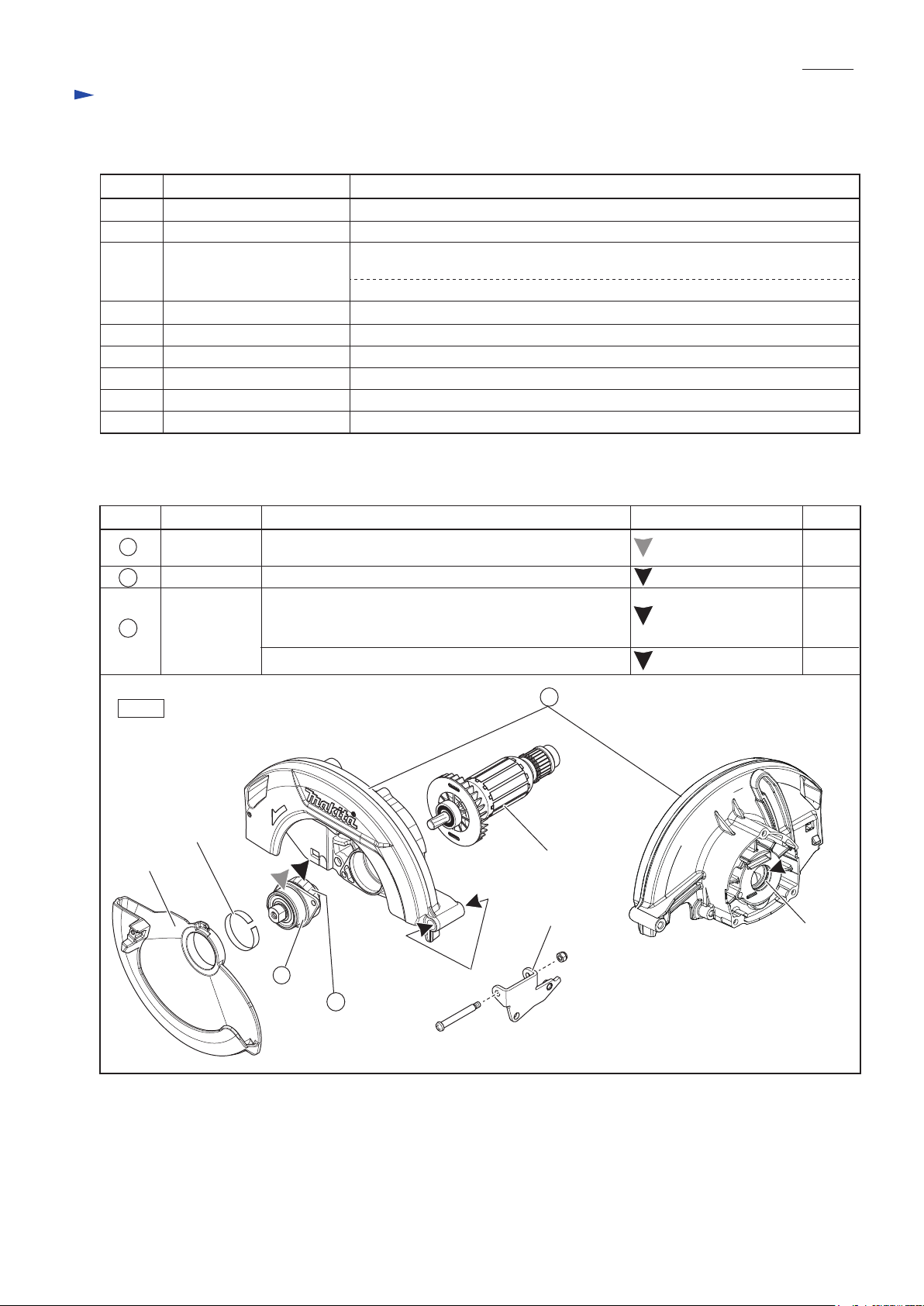
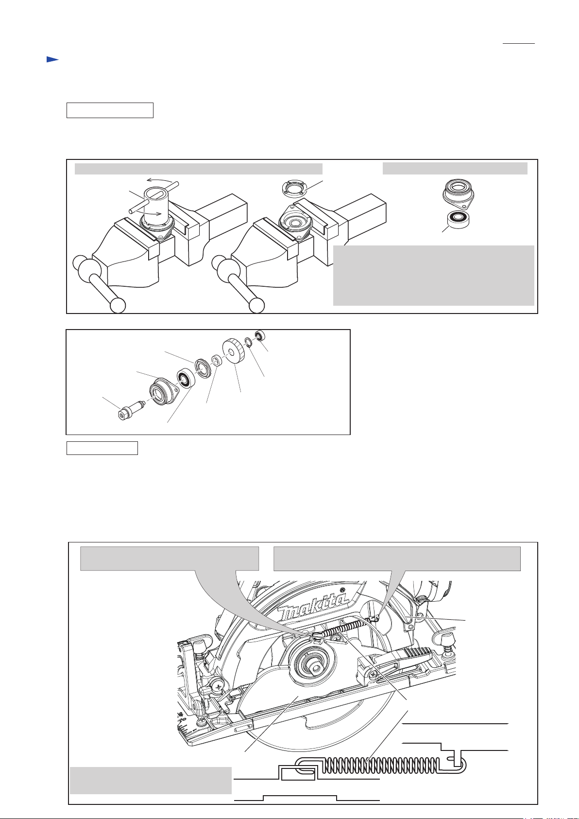
(1) Disassemble Safety cover as drawn in Fig. 7.
(2) Disassemble Bearing box section as drawn in Fig. 8.
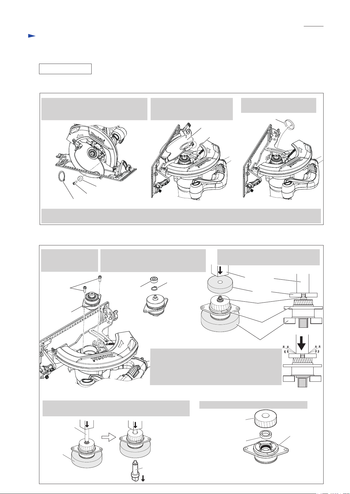
(3) Disassemble Motor section from Blade case as drawn in Fig. 12.
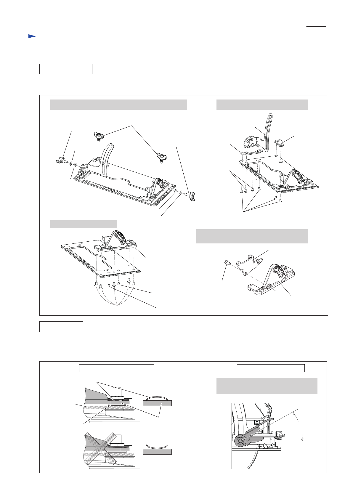
(4) Disassemble Base as drawn in Figs. 3 and 4. Blade case can be replaced.
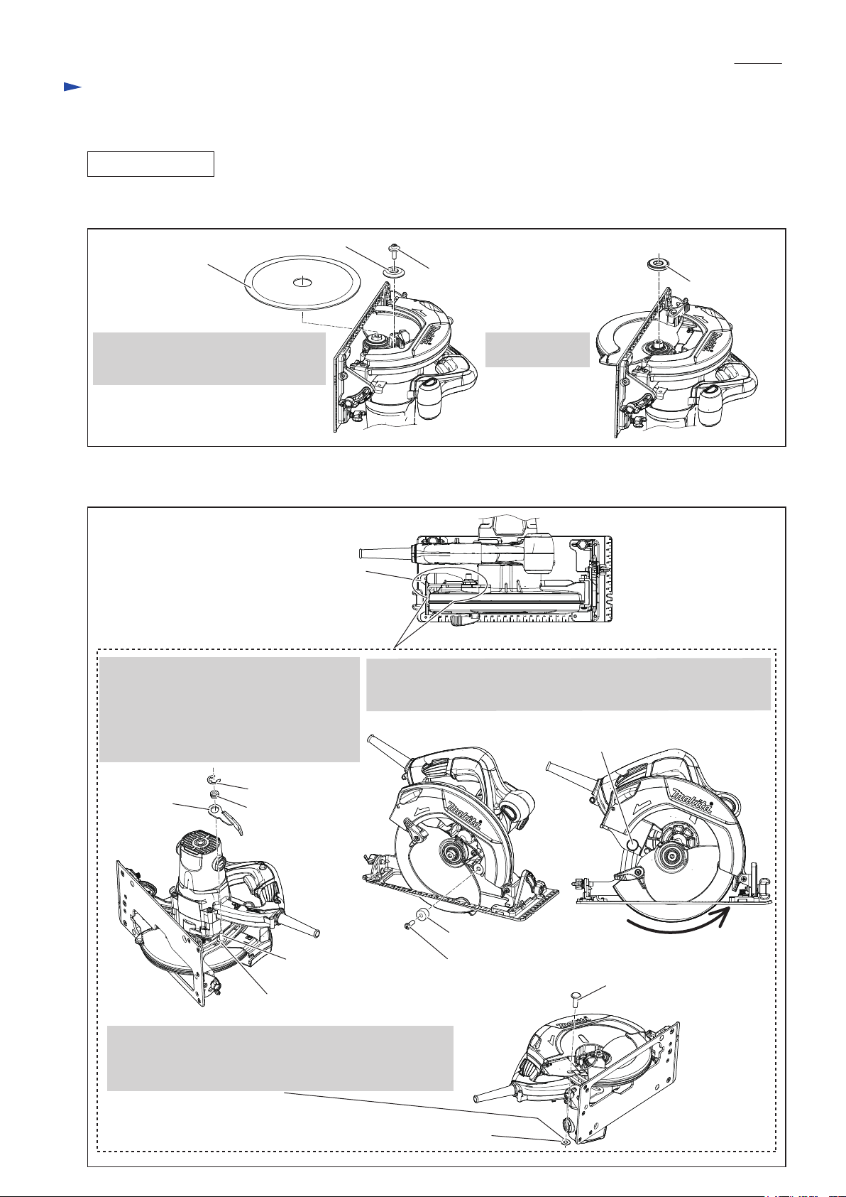
1.Insert 1R048 into the clearance between
Blade case and Lever 37 so as to hold
Safety cover and ensure the access to Blade.
Note: Make sure that Safety cover does not
move before doing step 2.
2. Apply the block of 1R208 to Base and adjust accuracy of
90° by turning M5x8 Hex socket set screw with Hex wrench 2.5
until the ruler plate of 1R208 touches Saw blade.
1R208
Block of 1R208
Ruler plate of 1R208
Saw blade
Safety cover
Hex wrench 2.5
(1) Set the machine as follows.
* Bevel angle: 90°
* Cutting depth: maximum depth
And tighten M6x21 Thumb screw and Lever plate to keep the above conditions.
(2) Adjust accuracy of 90° of Base to Saw blade as drawn in Fig. 13.
(3) Adjust the base in parallel to Saw blade as drawn in Fig. 14.
1R048
Blade case
Fig. 13
Fig. 14
M5x8 Hex socket head set screw
Note: Do not turn this M5x8 Hex socket set screw. This works as
a stopper for 6-7 Shoulder pin (hinge of Angular guide).
P 9/ 11
Lever 37
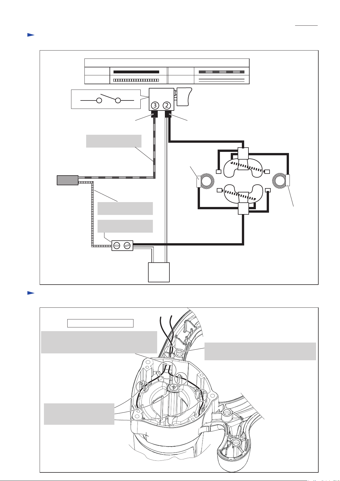
M4x8 Pan head screw (2 pcs.)Cord guard side of Base
1. Unlock the cord guard side of Base from Blade case by
loosening M4x8 Pan head screw slightly.
2. Move the cord guard side of Base by hand in the direction
of yellow arrows until the distance A is equal to B.
3. After finishing the adjustment, tighten M4x8 Pan head
screw firmly.
A
B
Repair

Power supply cord
3 2
Fig. D-1
Fig. D-2
WhiteBlue
Brown
Color index of lead wires' sheath
Black
Field
viewed from Fan side
Switch
Terminal block (if used)
Noise suppressor (if used)
Wiring of Field lead wires
Non insulated
sleeve
AWG18
(Single wire)
AWG18
AWG18
AWG20AWG20
AWG18
(Single wire)
Insulated receptacle (M3.5)Insulated receptacle (M3.5)
Black lead wire is used
for some countries.
Connector is used for
some countries
White lead wire is used
for some countries. Non insulated
sleeve
Pass Field lead wires through this square opening.
Note: Do not scratch them with this edge of
the square opening. Fix the Field lead wires in this Lead wire holder
so as not to be loose in Motor housing.
P 10/ 11
Circuit diagram
Wiring diagram
Fix Field lead wires in these
Lead wire holders so as not to
be loose in Motor housing

Noise suppressor
Opening of
Closed-end
connector
Strain relief
Switch
Do not put the Closed end connector
under Switch, if it is used instead of
Terminal block.
Do not put any Lead
wires on these Ribs.
Do not put any Lead
wires under Terminal
block.
Terminal
block
Setting of Noise suppressor (if used)
Face wire connected side to the bottom of
handle section and assemble Noise suppressor
to Handle.
Lead wires may interfere with assembling
of Handle cover. Therefore, put Noise
suppressor as drawn to the upper left.
Put closed-end connector to Handle section so that
the opening of Closed-end connector faces toward
Strain relief side, and then placce the Closed-end
connector here if it is used instead of Terminal block.
Setting of Closed-end connector (if used)
Fig. D-3
P 11/ 11
Wiring diagram
Other manuals for HS7601
8
Table of contents
Other Makita Saw manuals

Makita
Makita 5104 User manual

Makita
Makita 5008MG User manual

Makita
Makita 5604R User manual

Makita
Makita 5377MG Quick start guide

Makita
Makita LS1212 User manual

Makita
Makita LS0714 User manual

Makita
Makita LS003G User manual

Makita
Makita DJR360RM2 User manual

Makita
Makita Maktec MT241 Manual

Makita
Makita JR3000V User manual

Makita
Makita LC1230 User manual

Makita
Makita LF1000 User manual

Makita
Makita 5603R User manual

Makita
Makita JR3050T User manual

Makita
Makita DLS714 User manual

Makita
Makita LF1000 User manual

Makita
Makita M5802 User manual

Makita
Makita XBP03 User manual

Makita
Makita HS7010 User manual

Makita
Makita N5900B Manual