Makita DLS714 User manual

DLS714
EN Cordless Slide Compound
Miter Saw INSTRUCTION MANUAL 10
PL UФШЧТМКăКФuЦuХКtШrШаК IІSTRUKűJůăЇŰSŁUżI 24
HU VОгОtцФăЧцХФüХТăМsúsгяФШМsТsă
РцrЯпРяăПrцsг HASZNÁLATI KÉZIKÖNYV 39
SK
Akumulátorová posuvná
pokosová píla na
kombinované rezanie
NÁVOD NA OBSLUHU 54
CS Akumulátorová radiální
pokosová pila NÁVOD K OBSLUZE 68
UK
ăă
ăăă
ăă
ăă
82
RO ŻОrstruăЩОЧtruătТОrТăШЛХТМОă
МШЦЛТЧКtОĽăПrăМКЛХu MůІUůLăDźăIІSTRUűIUІI 98
DE Akku-Kapp. und
żОСruЧРssтРО ŰźTRIźŰSůІLźITUІż 113

1
32
4
5
6
7
89
10
11
12
12
13
14
15
16
18 17
Fig.1
19
20
21
22
23
24
25
22
Fig.2
1
1
Fig.3
1
Fig.4
2

2
21
3
Fig.5
121
Fig.6
1
2
Fig.7
1
Fig.8
1
Fig.9
1
2
Fig.10
1
Fig.11
1
Fig.12
3

1
2
2
Fig.13
1
1
Fig.14
Fig.15
1 1
3
45
3
2 2
Fig.16
1
2
Fig.17
Fig.18
Fig.19
4

1
2
Fig.20
1
Fig.21
1
2
34
5
Fig.22
1
2
Fig.23
1
2
3
Fig.24
2
1
Fig.25
1
2
4
3
Fig.26
2
1
3
Fig.27
5

12
Fig.28
1
Fig.29
4
2
3
1
Fig.30
1
2
3
Fig.31
123
45
6
Fig.32
1
2
2
Fig.33
123
45
Fig.34
123
45
6
Fig.35
6

1
2
3
Fig.36
12
Fig.37
2
8
4
5
3
1
6
7
7
8
Fig.38
1
2
3
4
Fig.39
1
2
Fig.40
2
1
Fig.41
Fig.42
Fig.43
7

Fig.44
123
Fig.45
(a) (b) (c) (d)
12
Fig.46
2
(a)
(b)
(a)
(b)
(b)
(a)
(b)
(a)
(a)
(b)
(c)
(d)
1
Fig.47
2
3
1
4
Fig.48
(a) (b) (c) (d)
12
Fig.49
1
2
3
Fig.50
1
Fig.51
8

Fig.52
1
2
Fig.53
1
Fig.54
1
2
3
Fig.55
2
1
5
4
3
Fig.56
1
2
3
Fig.57
1
23
Fig.58
1
Fig.59
9

10 ENGLISH
źІżLISHăĚЇrТРТЧКХăТЧstruМtТШЧsě
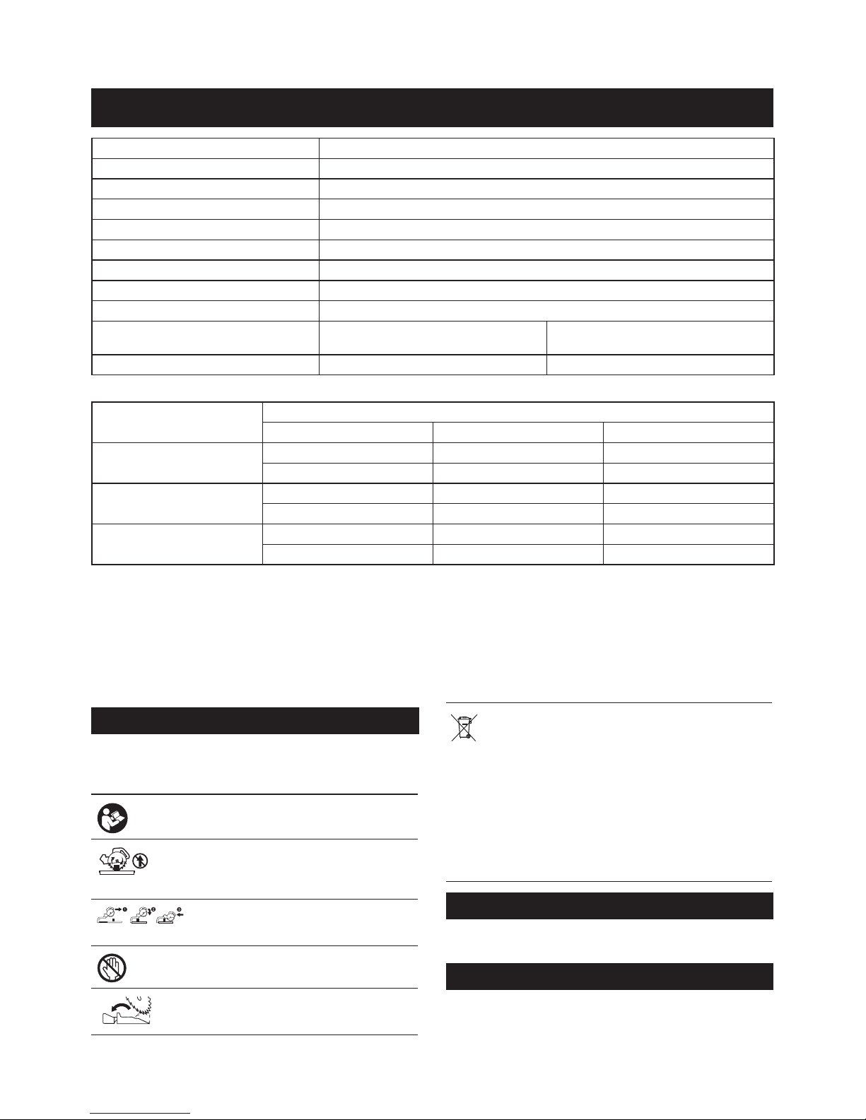
SPECIFICATIONS
Model: DLS714
Blade diameter 190 mm
Blade body thickness 1.3 mm - 2.0 mm
20 mm or 15.88 mm
Max. miter angle Left 47°, Right 57°
Max. bevel angle Left 45°, Right 5°
No load speed 5,700 min-1
Dimensions (L x W x H) 655 mm x 430 mm x 445 mm
Rated voltage D.C.36 V
Battery cartridge BL1815N, BL1820, BL1820B BL1830, BL1840, BL1840B, BL1850,
BL1850B
Net weight 13.0 kg 13.5 kg
Cutting capacities (H x W) with blade 190 mm in diameter
Miter angle Bevel angle
Őő°ăĚХОПtě 0° ő°ăĚrТРСtě
0° 40 mm x 300 mm 52 mm x 300 mm 40 mm x 300 mm
45 mm x 265 mm (NOTE 1) 60 mm x 265 mm (NOTE 1) –
45° (left and right) 40 mm x 212 mm 52 mm x 212 mm –
45 mm x 185 mm (NOTE 2) 60 mm x 185 mm (NOTE 2) –
57° (right) –52 mm x 163 mm –
–60 mm x 145 mm (NOTE 3) –
1. Max. Cutting capacity when using a wood facing 20 mm thickness
2. Max. Cutting capacity when using a wood facing 15 mm thickness
3. Max. Cutting capacity when using a wood facing 10 mm thickness
without notice.
• Weight, with battery cartridge, according to EPTA-Procedure 01/2003
Symbols
The following show the symbols used for the equip-
ment. Be sure that you understand their meaning before
use.
Read instruction manual.
holding the saw head down, after making
cuts, until the blade has come to a com-
plete stop.
-
riage fully and press down handle, then
push carriage toward the guide fence.
blade.
Always set SUB-FENCE to left position
when performing left bevel cuts. Failure to
C d
N i - M H
L i - i o n
Only for EU countries
Do not dispose of electric equipment or battery
pack together with household waste material!
In observance of the European Directives,
on Waste Electric and Electronic
Equipment and Batteries and Accumulators
and Waste Batteries and Accumulators
and their implementation in accordance
with national laws, electric equipment and
batteries and battery pack(s) that have
reached the end of their life must be col-
lected separately and returned to an envi-
ronmentally compatible recycling facility.
Intended use
The tool is intended for accurate straight and miter
cutting in wood.
Noise
The typical A-weighted noise level determined accord-
ing to EN61029:
Sound pressure level (LpA) : 88 dB(A)
Sound power level (LWA) : 97 dB (A)
Uncertainty (K) : 3 dB(A)

11ENGLISH
АůRІIІżŚ АОКrăОКrăЩrШtОМtТШЧ.
Vibration
The vibration total value (tri-axial vector sum) deter-
mined according to EN61029:
Vibration emission (ah) : 2.5 m/s2or less
Uncertainty (K) : 1.5 m/s2
NOTE: The declared vibration emission value has
been measured in accordance with the standard test
method and may be used for comparing one tool with
another.
NOTE: The declared vibration emission value
may also be used in a preliminary assessment of
exposure.
АůRІIІżŚ The vibration emission during actual
use of the power tool can differ from the declared
emission value depending on the ways in which the
tool is used.
АůRІIІżŚ Be sure to identify safety measures to
protect the operator that are based on an estimation
of exposure in the actual conditions of use (taking
account of all parts of the operating cycle such as
the times when the tool is switched off and when it is
running idle in addition to the trigger time).
źűăDОМХКrКtТШЧăШПăűШЧПШrЦТtв
For European countries only
Makita declares that the following Machine(s):
Designation of Machine: Cordless Slide Compound
Miter Saw
Model No./ Type: DLS714
Conforms to the following European Directives:
2006/42/EC
They are manufactured in accordance with the following
standard or standardized documents: EN61029
available from:
Makita, Jan-Baptist Vinkstraat 2, 3070, Belgium
16.1.2015
Yasushi Fukaya
Director
Makita, Jan-Baptist Vinkstraat 2, 3070, Belgium
żОЧОrКХăЩШаОrătШШХăsКПОtвăаКrЧТЧРs
АůRІIІżŚ RОКНăКХХăsКПОtвăаКrЧТЧРsăКЧНăКХХă
ТЧstruМtТШЧs.ăFailure to follow the warnings and
SКЯОăКХХăаКrЧТЧРsăКЧНăТЧstruМ-
tТШЧsăПШrăПuturОărОПОrОЧМО.
The term "power tool" in the warnings refers to your
mains-operated (corded) power tool or battery-operated
(cordless) power tool.
űШrНХОssăЦТtОrăsКаăsКПОtвăаКrЧТЧРs
1. KООЩăСКЧНsăШutăШПăЩКtСăШПăsКаăЛХКНО.ăůЯШТНă
МШЧtКМtăаТtСăКЧвăМШКstТЧРăЛХКНО.ăItăМКЧăstТХХă
МКusОăsОЯОrОăТЧУurв.
2. űСОМФătСОăsКаăЛХКНОăМКrОПuХХвăПШrăМrКМФsăШră
НОПШrЦКtТШЧăЛОПШrОăШЩОrКtТШЧ.
RОЩХКМОăНКЦКРОНăЛХКНОsăТЦЦОНТКtОХв.
3. RОЩХКМОătСОăФОrПăЛШКrНăаСОЧăаШrЧ.
4. UsОăШЧХвăsКаăЛХКНОsăsЩОМТiОНăЛвătСОăЦКЧuПКМ-
turОrăаСТМСăМШЧПШrЦătШăźІŘŐ7ľ1.
5. DШăЧШtăusОăsКаăЛХКНОsăЦКЧuПКМturОНăПrШЦă
СТРСăsЩООНăstООХ.
6. АОКrăОвОăЩrШtОМtТШЧ.
7. АОКrăСОКrТЧРăЩrШtОМtТШЧătШărОНuМОătСОărТsФăШПă
СОКrТЧРăХШss.
8. АОКrăРХШЯОsăПШrăСКЧНХТЧРăsКаăЛХКНОăĚsКаă
ЛХКНОsăsСКХХăЛОăМКrrТОНăТЧăКăСШХНОrăаСОrОЯОră
ЩrКМtТМКЛХОěăКЧНărШuРСăЦКtОrТКХ.
9. űШЧЧОМtăЦТtОrăsКаsătШăКăНustăМШХХОМtТЧРăНОЯТМОă
аСОЧăsКаТЧР.
10. SОХОМtăsКаăЛХКНОsăТЧărОХКtТШЧătШătСОăЦКtОrТКХătШă
ЛОăМut.
11. DШăЧШtăusОătСОăsКаătШăМutăШtСОrătСКЧăаШШН.
12. ůХаКвsăsОМurОăКХХăЦШЯТЧРăЩШrtТШЧsăЛОПШrОăМКr-
rвТЧРătСОătШШХ.ăАСОЧăХТПtТЧРăШrăМКrrвТЧРătСОătШШХĽă
НШăЧШtăusОătСОăРuКrНăКsăКăМКrrвТЧРăСКЧНХО.
13. DШăЧШtăШЩОrКtОăsКаăаТtСШutăРuКrНsăТЧăЩХКМО.ă
űСОМФăЛХКНОăРuКrНăПШrăЩrШЩОrăМХШsТЧРăЛОПШrОă
ОКМСăusО.ăDШăЧШtăШЩОrКtОăsКаăТПăЛХКНОăРuКrНă
НШОsăЧШtăЦШЯОăПrООХвăКЧНăМХШsОăТЧstКЧtХв.ă
ІОЯОrăМХКЦЩăШrătТОătСОăЛХКНОăРuКrНăТЧtШătСОă
open position.
14. KООЩătСОălШШrăКrОКăПrООăШПăХШШsОăЦКtОrТКХăО.Р.ă
МСТЩsăКЧНăМutľШППs.
15. UsОăШЧХвăsКаăЛХКНОsătСКtăКrОăЦКrФОНăаТtСăКă
ЦКбТЦuЦăsЩООНăОquКХătШăШrăСТРСОrătСКЧătСОăЧШă
ХШКНăsЩООНăЦКrФОНăШЧătСОătШШХ.
16. АСОЧătСОătШШХăТsăittОНăаТtСăКăХКsОrăШrăLźDĽăНШă
ЧШtărОЩХКМОătСОăХКsОrăШrăLźDăаТtСăКăНТППОrОЧtă
type. Ask an authorized service center for repair.
17. ІОЯОrărОЦШЯОăКЧвăМutľШППsăШrăШtСОrăЩКrtsăШПătСОă
аШrФЩТОМОăПrШЦătСОăМuttТЧРăКrОКăаСТХstătСОătШШХă
ТsăruЧЧТЧРăаТtСăКЧăuЧРuКrНОНăsКаăЛХКНО.
18. DШăЧШtăЩОrПШrЦăКЧвăШЩОrКtТШЧăПrООСКЧН. The
turn base and guide fence with the vise during all
operations. Never use your hand to secure the
workpiece.
19. źЧsurОătСКtătСОătШШХăТsăstКЛХОăЛОПШrОăОКМСăМut.
20. ŻТбătСОătШШХătШăКăаШrФăЛОЧМСĽăТПăЧООНОН.
21. SuЩЩШrtăХШЧРăаШrФЩТОМОsăаТtСăКЩЩrШЩrТКtОă
additional supports.
22.
ІОЯОrăМutăsШăsЦКХХăаШrФЩТОМОăаСТМСăМКЧЧШtăЛОă
sОМurОХвăСОХНăЛвătСОăЯТsО. Improperly held workpiece
23. ІОЯОrărОКМСăКrШuЧНăsКаăЛХКНО.
24. TurЧăШППătШШХăКЧНăаКТtăПШrăsКаăЛХКНОătШăstШЩă
ЛОПШrОăЦШЯТЧРăаШrФЩТОМОăШrăМСКЧРТЧРă
settings.
25. DТsМШЧЧОМtătСОăЩХuРăПrШЦătСОăЩШаОrăsШurМОă
КЧН/ШrătСОăЛКttОrвăЩКМФăПrШЦătСОăЩШаОrătШШХă
ЛОПШrОăМСКЧРТЧРăЛХКНОăШrăsОrЯТМТЧР.

12 ENGLISH
26. StШЩЩОrăЩТЧăаСТМСăХШМФsătСОăМuttОrăСОКНăНШаЧă
ТsăПШrăМКrrвТЧРăКЧНăstШrКРОăЩurЩШsОsăШЧХвăКЧНă
ЧШtăПШrăКЧвăМuttТЧРăШЩОrКtТШЧs.
27. DШăЧШtăusОătСОătШШХăТЧătСОăЩrОsОЧМОăШПălКЦЦК-
ble liquids or gases. The electrical operation of
28. UsОăШЧХвălКЧРОsăsЩОМТiОНăПШrătСТsătШШХ.
29.
ŰОăМКrОПuХăЧШtătШăНКЦКРОătСОăКrЛШrĽălКЧРОsăĚОsЩО-
МТКХХвătСОăТЧstКХХТЧРăsurПКМОěăШrăЛШХt.ăDКЦКРОătШă
tСОsОăЩКrtsăМШuХНărОsuХtăТЧăЛХКНОăЛrОКФКРО.
30. MКФОăsurОătСКtătСОăturЧăЛКsОăТsăЩrШЩОrХвă
sОМurОНăsШăТtăаТХХăЧШtăЦШЯОăНurТЧРăШЩОrКtТШЧ.
31. ŻШrăвШurăsКПОtвĽărОЦШЯОătСОăМСТЩsĽăsЦКХХă
ЩТОМОsĽăОtМ.ăПrШЦătСОătКЛХОătШЩăЛОПШrОă
operation.
32. ůЯШТНăМuttТЧРăЧКТХs.ăIЧsЩОМtăПШrăКЧНărОЦШЯОăКХХă
ЧКТХsăПrШЦătСОăаШrФЩТОМОăЛОПШrОăШЩОrКtТШЧ.
33. MКФОăsurОătСОăsСКПtăХШМФăТsărОХОКsОНăЛОПШrОătСОă
sаТtМСăТsăturЧОНăШЧ.
34. ŰОăsurОătСКtătСОăЛХКНОăНШОsăЧШtăМШЧtКМtătСОă
turЧăЛКsОăТЧătСОăХШаОstăЩШsТtТШЧ.
35. HШХНătСОăСКЧНХОăirЦХв.ăŰОăКаКrОătСКtătСОăsКаă
ЦШЯОsăuЩăШrăНШаЧăsХТРСtХвăНurТЧРăstКrtľuЩăКЧНă
stopping.
36. MКФОăsurОătСОăЛХКНОăТsăЧШtăМШЧtКМtТЧРătСОă
аШrФЩТОМОăЛОПШrОătСОăsаТtМСăТsăturЧОНăШЧ.
37. ŰОПШrОăusТЧРătСОătШШХăШЧăКЧăКМtuКХăаШrФЩТОМОĽă
ХОtăТtăruЧăПШrăКăаСТХО.ăАКtМСăПШrăЯТЛrКtТШЧăШră
аШЛЛХТЧРătСКtăМШuХНăТЧНТМКtОăЩШШrăТЧstКХХКtТШЧă
ШrăКăЩШШrХвăЛКХКЧМОНăЛХКНО.
38. АКТtăuЧtТХătСОăЛХКНОăКttКТЧsăПuХХăsЩООНăЛОПШrОă
МuttТЧР.
39. StШЩăШЩОrКtТШЧăТЦЦОНТКtОХвăТПăвШuăЧШtТМОăКЧв-
tСТЧРăКЛЧШrЦКХ.
40. DШăЧШtăКttОЦЩtătШăХШМФătСОătrТРРОrăТЧătСОăШЧă
position.
41. ŰОăКХОrtăКtăКХХătТЦОsĽăОsЩОМТКХХвăНurТЧРărОЩОtТ-
tТЯОĽăЦШЧШtШЧШusăШЩОrКtТШЧs.ăDШăЧШtăЛОăХuХХОНă
ТЧtШăКăПКХsОăsОЧsОăШПăsОМurТtв.ăŰХКНОsăКrОă
ОбtrОЦОХвăuЧПШrРТЯТЧР.
42. ůХаКвsăusОăКММОssШrТОsărОМШЦЦОЧНОНăТЧătСТsă
ЦКЧuКХ.ăUsОăШПăТЦЩrШЩОrăКММОssШrТОsăsuМСăКsă
КЛrКsТЯОăаСООХsăЦКвăМКusОăКЧăТЧУurв.
43. TКФОăМКrОăаСОЧăsХШttТЧР.
44. SШЦОăНustăМrОКtОНăПrШЦăШЩОrКtТШЧăМШЧtКТЧsă
МСОЦТМКХsăФЧШаЧătШăМКusОăМКЧМОrĽăЛТrtСă
НОПОМtsăШrăШtСОrărОЩrШНuМtТЯОăСКrЦ.ăSШЦОă
ОбКЦЩХОsăШПătСОsОăМСОЦТМКХsăКrОŚ
•
ХОКНăПrШЦăХОКНľЛКsОНľЩКТЧtОНăЦКtОrТКХăКЧНĽ
• КrsОЧТМăКЧНăМСrШЦТuЦăПrШЦăМСОЦТМКХ-
ly-treated lumber.
ВШurărТsФăПrШЦătСОsОăОбЩШsurОsăЯКrТОsĽă
НОЩОЧНТЧРăШЧăСШаăШПtОЧăвШuăНШătСТsătвЩОă
ШПăаШrФ.ăTШărОНuМОăвШurăОбЩШsurОătШătСОsОă
МСОЦТМКХsŚăаШrФăТЧăКăаОХХăЯОЧtТХКtОНăКrОКăКЧНă
аШrФăаТtСăКЩЩrШЯОНăsКПОtвăОquТЩЦОЧtĽăsuМСăКsă
tСШsОăНustăЦКsФsătСКtăКrОăsЩОМТКХХвăНОsТРЧОНă
tШăiХtОrăШutăЦТМrШsМШЩТМăЩКrtТМХОs.
45. TШărОНuМОătСОăОЦТttОНăЧШТsОĽăКХаКвsăЛОăsurОă
tСКtătСОăЛХКНОăТsăsСКrЩăКЧНăМХОКЧ.
46. TСОăШЩОrКtШrăТsăКНОquКtОХвătrКТЧОНăТЧătСОăusОĽă
КНУustЦОЧtăКЧНăШЩОrКtТШЧăШПătСОăЦКМСТЧО.
SAVE THESE INSTRUCTIONS.
АůRІIІżŚ DЇăІЇTăХОtăМШЦПШrtăШrăПКЦТХТКrТtвă
аТtСăЩrШНuМtăĚРКТЧОНăПrШЦărОЩОКtОНăusОěărОЩХКМОă
strТМtăКНСОrОЧМОătШăsКПОtвăruХОsăПШrătСОăsuЛУОМtă
ЩrШНuМt.ăMISUSźăШrăПКТХurОătШăПШХХШаătСОăsКПОtвă
ruХОsăstКtОНăТЧătСТsăТЧstruМtТШЧăЦКЧuКХăЦКвăМКusОă
sОrТШusăЩОrsШЧКХăТЧУurв.
IЦЩШrtКЧtăsКПОtвăТЧstruМtТШЧsăПШră
ЛКttОrвăМКrtrТНРО
1. ŰОПШrОăusТЧРăЛКttОrвăМКrtrТНРОĽărОКНăКХХăТЧstruМ-
tТШЧsăКЧНăМКutТШЧКrвăЦКrФТЧРsăШЧăĚ1ěăЛКttОrвă
МСКrРОrĽăĚŇěăЛКttОrвĽăКЧНăĚňěăЩrШНuМtăusТЧРă
battery.
2. DШăЧШtăНТsКssОЦЛХОăЛКttОrвăМКrtrТНРО.
3. IПăШЩОrКtТЧРătТЦОăСКsăЛОМШЦОăОбМОssТЯОХвă
sСШrtОrĽăstШЩăШЩОrКtТЧРăТЦЦОНТКtОХв.ăItăЦКвă
rОsuХtăТЧăКărТsФăШПăШЯОrСОКtТЧРĽăЩШssТЛХОăЛurЧsă
and even an explosion.
4. IПăОХОМtrШХвtОăРОtsăТЧtШăвШurăОвОsĽărТЧsОătСОЦă
ШutăаТtСăМХОКrăаКtОrăКЧНăsООФăЦОНТМКХăКttОЧ-
tТШЧărТРСtăКаКв.ăItăЦКвărОsuХtăТЧăХШssăШПăвШură
ОвОsТРСt.
5. DШăЧШtăsСШrtătСОăЛКttОrвăМКrtrТНРОŚ
(1) DШăЧШtătШuМСătСОătОrЦТЧКХsăаТtСăКЧвăМШЧ-
НuМtТЯОăЦКtОrТКХ.
(2) ůЯШТНăstШrТЧРăЛКttОrвăМКrtrТНРОăТЧăКăМШЧ-
tКТЧОrăаТtСăШtСОrăЦОtКХăШЛУОМtsăsuМСăКsă
ЧКТХsĽăМШТЧsĽăОtМ.
(3) DШăЧШtăОбЩШsОăЛКttОrвăМКrtrТНРОătШăаКtОră
or rain.
ůăЛКttОrвăsСШrtăМКЧăМКusОăКăХКrРОăМurrОЧtă
lШаĽăШЯОrСОКtТЧРĽăЩШssТЛХОăЛurЧsăКЧНăОЯОЧăКă
breakdown.
6. DШăЧШtăstШrОătСОătШШХăКЧНăЛКttОrвăМКrtrТНРОăТЧă
ХШМКtТШЧsăаСОrОătСОătОЦЩОrКturОăЦКвărОКМСăШră
ОбМООНăő0ă°űăĚ1ŇŇă°Żě.
7. DШăЧШtăТЧМТЧОrКtОătСОăЛКttОrвăМКrtrТНРОăОЯОЧăТПă
ТtăТsăsОЯОrОХвăНКЦКРОНăШrăТsăМШЦЩХОtОХвăаШrЧă
Шut.ăTСОăЛКttОrвăМКrtrТНРОăМКЧăОбЩХШНОăТЧăКăirО.
8. ŰОăМКrОПuХăЧШtătШăНrШЩăШrăstrТФОăЛКttОrв.
9. Do not use a damaged battery.
10. ŻШХХШаăвШurăХШМКХărОРuХКtТШЧsărОХКtТЧРătШăНТs-
ЩШsКХăШПăЛКttОrв.
SAVE THESE INSTRUCTIONS.
TТЩsăПШrăЦКТЧtКТЧТЧРăЦКбТЦuЦă
ЛКttОrвăХТПО
1. űСКrРОătСОăЛКttОrвăМКrtrТНРОăЛОПШrОăМШЦЩХОtОХвă
НТsМСКrРОН.ăůХаКвsăstШЩătШШХăШЩОrКtТШЧăКЧНă
МСКrРОătСОăЛКttОrвăМКrtrТНРОăаСОЧăвШuăЧШtТМОă
less tool power.
2. ІОЯОrărОМСКrРОăКăПuХХвăМСКrРОНăЛКttОrвăМКr-
trТНРО.ăЇЯОrМСКrРТЧРăsСШrtОЧsătСОăЛКttОrвă
sОrЯТМОăХТПО.
3. űСКrРОătСОăЛКttОrвăМКrtrТНРОăаТtСărШШЦătОЦ-
ЩОrКturОăКtă10ă°űăľăŐ0ă°űăĚő0ă°Żăľă10Őă°Żě.ăLОtă
КăСШtăЛКttОrвăМКrtrТНРОăМШШХăНШаЧăЛОПШrОă
МСКrРТЧРăТt.
4. űСКrРОătСОăЛКttОrвăМКrtrТНРОăТПăвШuăНШăЧШtăusОă
ТtăПШrăКăХШЧРăЩОrТШНăĚЦШrОătСКЧăsТбăЦШЧtСsě.ă

13ENGLISH
PARTS DESCRIPTION
Fig.1
1Lock-off button 2Switch trigger 3Blade case 4
lower limit position)
5-
mum cutting capacity)
6Stopper arm 7Dust bag 8Bevel scale
9Blade guard 10 Vertical vice 11 Guide fence 12 Holder
13 Lock lever (for turn base) 14 Grip (for turn base) 15
base)
16 Kerf board
17 Pointer (for miter angle) 18 Turn base - - - -
Fig.2
19 Slide pole (upper) 20 Thumb screw (for lock-
ing upper slide pole)
21 Hex wrench 22 Clamp screw (for locking
holder)
23 Lever (for bevel angle
24 Slide pole (lower) 25 Thumb screw (for lock-
ing lower slide pole)
- -
INSTALLATION
ŰОЧМСăЦШuЧtТЧР
АůRІIІżŚ źЧsurОătСКtătСОătШШХăНШОsăЧШtăЦШЯОă
ШЧătСОăsuЩЩШrtТЧРăsurПКМО. Movement of the miter
saw on the supporting surface while cutting may
1. Fix the base to a level and stable surface, screw-
ing with two bolts. This helps to prevent from tipping and
Fig.3: 1. Bolt
2. -
-
face to keep the tool stable.
Fig.4:
FUNCTIONAL
DESCRIPTION
АůRІIІżŚ ůХаКвsăЛОăsurОătСКtătСОătШШХăТsă
sаТtМСОНăШППăКЧНătСОăЛКttОrвăМКrtrТНРОăТsărОЦШЯОНă
ЛОПШrОăКНУustТЧРăШrăМСОМФТЧРătСОăПuЧМtТШЧsăШЧă
tСОătШШХ. Failure to switch off and remove the battery
accidental start-up.
Installing or removing battery
МКrtrТНРО
CAUTION: ůХаКвsăsаТtМСăШППătСОătШШХăЛОПШrОă
ТЧstКХХТЧРăШrărОЦШЯТЧРăШПătСОăЛКttОrвăМКrtrТНРО.
CAUTION: HШХНătСОătШШХăКЧНătСОăЛКttОrвăМКr-
trТНРОăirЦХвăаСОЧăТЧstКХХТЧРăШrărОЦШЯТЧРăЛКttОrвă
МКrtrТНРО. Failure to hold the tool and the battery
and result in damage to the tool and battery cartridge
Fig.5: 1. Red indicator 2. Button 3. Battery
cartridge
To remove the battery cartridge, slide it from the tool
while sliding the button on the front of the cartridge.
To install the battery cartridge, align the tongue on the
battery cartridge with the groove in the housing and slip
it into place. Insert it all the way until it locks in place
with a little click. If you can see the red indicator on the
upper side of the button, it is not locked completely.
CAUTION: ůХаКвsăТЧstКХХătСОăЛКttОrвăМКrtrТНРОă
ПuХХвăuЧtТХătСОărОНăТЧНТМКtШrăМКЧЧШtăЛОăsООЧ. If not,
you or someone around you.
CAUTION: DШăЧШtăТЧstКХХătСОăЛКttОrвăМКrtrТНРОă
ПШrМТЛХв. If the cartridge does not slide in easily, it is
not being inserted correctly.
NOTE: The tool does not work with only one battery
cartridge.
TШШХă/ăЛКttОrвăЩrШtОМtТШЧăsвstОЦ
The tool is equipped with a tool/battery protection
system. This system automatically cuts off power to
the motor to extend tool and battery life. The tool will
automatically stop during operation if the tool or battery
is placed under one of the following conditions. In some
conditions, the indicators light up.

14 ENGLISH
ЇЯОrХШКНăЩrШtОМtТШЧ
When the tool is operated in a manner that causes it to
draw an abnormally high current, the tool automatically
stops without any indication. In this situation, turn the
tool off and stop the application that caused the tool to
become overloaded. Then turn the tool on to restart.
ЇЯОrСОКtăЩrШtОМtТШЧ
on Blinking
When the tool is overheated, the tool stops automati-
cally, and the battery indicator blink about 60 seconds.
In this situation, let the tool cool down before turning the
tool on again.
ЇЯОrНТsМСКrРОăЩrШtОМtТШЧ
When the battery capacity becomes low, the tool stops
automatically. If the product does not operate even
when the switches are operated, remove the batteries
from the tool and charge the batteries.
IЧНТМКtТЧРătСОărОЦКТЧТЧРăЛКttОrвă
МКЩКМТtв
Fig.6: 1. Battery indicator 2. Check button
Press the check button to indicate the remaining battery
capacities. The battery indicators correspond to each
battery.
ŰКttОrвăТЧНТМКtШrăstКtus Remaining
battery
МКЩКМТtв
On ЇПП Blinking
50% - 100%
20% - 50%
0% - 20%
Charge the
battery
IЧНТМКtТЧРătСОărОЦКТЧТЧРăЛКttОrвă
МКЩКМТtв
Only for battery cartridges with "B" at the end of the
model number
Fig.7: 1. Indicator lamps 2. Check button
Press the check button on the battery cartridge to indi-
cate the remaining battery capacity. The indicator lamps
light up for few seconds.
IЧНТМКtШrăХКЦЩs Remaining
МКЩКМТtв
LТРСtОН ЇПП Blinking
75% to 100%
50% to 75%
25% to 50%
0% to 25%
Charge the
battery.
The battery
may have
malfunctioned.
NOTE: Depending on the conditions of use and the
ambient temperature, the indication may differ slightly
from the actual capacity.
ůutШЦКtТМăsЩООНăМСКЧРОăПuЧМtТШЧ
Fig.8: 1. Mode indicator
MШНОăТЧНТМКtШrăstКtus Operation mode
High speed mode
High torque mode
This tool has "high speed mode" and "high torque
mode". It automatically changes operation mode
depending on the work load. When mode indicator
lights up during operation, the tool is in high torque
mode.
Stopper pin
CAUTION: ůХаКвsăСШХНătСОăСКЧНХОăаСОЧă
rОХОКsТЧРătСОăstШЩЩОrăЩТЧ. Otherwise the handle
To release the stopper pin, keep applying a slight
downward pressure on the handle and then pulling the
stopper pin.
Fig.9: 1. Stopper pin
Blade guard
АůRІIІżŚ ІОЯОrăНОПОКtăШrărОЦШЯОătСОăЛХКНОă
РuКrНăШrătСОăsЩrТЧРăаСТМСăКttКМСОsătШătСОăРuКrН.
An exposed blade as a result of defeated guarding
АůRІIІżŚ ІОЯОrăusОătСОătШШХăТПătСОăЛХКНОă
РuКrНăШrăsЩrТЧРăКrОăНКЦКРОНĽăПКuХtвăШrărОЦШЯОН.
Operation of the tool with a damaged, faulty or

15ENGLISH
CAUTION: Always maintain the blade guard in
good condition for safe operation. Stop the operation
immediately if there are any irregularity of the blade
guard. Check to assure spring loaded return action
of guard.
ŻШrătШШХsăаТtСăЛХКНОăРuКrНărОХОКsОăХОЯОră
Fig.10: 1. Blade guard A 2. Blade guard B
When lowering the handle, the blade guard A rises
automatically. The blade guard B rises as it contacts a
workpiece. The guards are spring loaded so it returns to
its original position when the cut is completed and the
handle is raised.
ŻШrătШШХsăаТtСШutăЛХКНОăРuКrНărОХОКsОăХОЯОră
Fig.11: 1. Blade guard
When lowering the handle, the blade guard raises
automatically. The guard is spring loaded so it returns to
its original position when the cut is completed and the
handle is raised.
Cleaning
Fig.12: 1. Blade guard
If the transparent blade guard becomes dirty, or saw-
dust adheres to it in such a way that the blade and/or
workpiece is no longer easily visible, remove the battery
cartridge and clean the guard carefully with a damp
cloth. Do not use solvents or any petroleum-based
cleaners on the plastic guard because this may cause
damage to the guard.
For cleaning, raise the blade guard by referring to
"Installing or removing saw blade".
After cleaning, make sure to return the blade and center
cover and tighten the hex socket bolt.
1. Make sure that the tool is switched off and the
battery cartridges are removed.
2. Turn the hex socket bolt counterclockwise using
the supplied hex wrench with holding the center cover.
3. Raise the blade guard and center cover.
4. When cleaning is complete, return the center
cover and tighten the hex socket bolt by performing the
steps above in reverse.
АůRІIІżŚ DШăЧШtărОЦШЯОăsЩrТЧРăСШХНТЧРăЛХКНОă
guard. If guard becomes damaged in course of time
or UV light exposure, contact a Makita service center
for replacement. DO NOT DEFEAT OR REMOVE
żUůRD.
PШsТtТШЧТЧРăФОrПăЛШКrН
This tool is provided with the kerf boards in the turn
base to minimize tearing on the exit side of a cut. The
kerf boards as follows:
1. Make sure to remove the battery cartridge. Then,
loosen all the screws (2 each on left and right) securing
the kerf boards.
Fig.13: 1. Kerf board 2. Screw
2. Re-tighten them only to the extent that the kerf
boards can still be easily moved by hand.
3. Lower the handle fully and push in the stopper pin
to lock the handle in the lowered position.
4. Loosen two clamp screws which secure the slide
poles.
Fig.14: 1. Thumb screw
5. Pull the carriage toward you fully.
6.
contact the sides of the blade teeth.
Fig.15
Fig.16: 1. Saw blade 2. Blade teeth 3. Kerf
board 4. Left bevel cut 5. Straight cut
7.
8. Push the carriage toward the guide fence fully and
-
tact the sides of blade teeth.
9.
10. -
per pin and raise the handle. Then tighten all the screws
securely.
NOTICE: ůПtОrăsОttТЧРătСОăЛОЯОХăКЧРХОăОЧsurОătСКtă
tСОăФОrПăЛШКrНsăКrОăКНУustОНăЩrШЩОrХв. Correct
support of the workpiece and minimizing workpiece
tear out.
MКТЧtКТЧТЧРăЦКбТЦuЦăМuttТЧРă
МКЩКМТtв
cutting capacity for a 190 mm saw blade.
When installing a new blade, always check the lower
follows:
1. Remove the battery cartridge. Then, push the car-
riage toward the guide fence fully and lower the handle
completely.
Fig.17:
2.
the saw blade comes slightly below the cross section of
the guide fence and the top surface of the turn base.
Fig.18
3. Rotate the blade by hand while holding the handle
all the way down to be sure that the blade does not
necessary.
АůRІIІżŚ ůПtОrăТЧstКХХТЧРăКăЧОаăЛХКНОăКЧНă
аТtСătСОăЛКttОrвăМКrtrТНРОărОЦШЯОНĽăКХаКвsăЛОă
surОătСКtătСОăЛХКНОăНШОsăЧШtăМШЧtКМtăКЧвăЩКrtăШПă
tСОăХШаОrăЛКsОăаСОЧătСОăСКЧНХОăТsăХШаОrОНăМШЦ-
pletely. If a blade makes contact with the base it may
Fig.19
Stopper arm
The lower limit position of the blade can be easily
stopper arm in the direction of the arrow as shown in
handle fully to check the result.
Fig.20:

16 ENGLISH
SuЛľПОЧМО
CAUTION: АСОЧăЩОrПШrЦТЧРăХОПtăЛОЯОХăМutsĽălТЩă
tСОăsuЛľПОЧМОăШutаКrН.ăOtherwise, it may contact
the blade or a part of the tool, and may result in seri-
Fig.21: 1. Sub-fence
This tool is equipped with the sub-fence. Usually posi-
tion the sub-fence inside. However, when performing
ůНУustТЧРătСОăЦТtОrăКЧРХО
Fig.22: 1. Turn base 2. Pointer 3. Miter scale
4. Lock lever 5. Grip
1. Loosen the grip counterclockwise.
2.
angle of the turn base. Use the pointer and the miter
scale as a guide.
3.
CAUTION: ůПtОrăМСКЧРТЧРătСОăЦТtОrăКЧРХОĽă
КХаКвsăsОМurОătСОăturЧăЛКsОăЛвătТРСtОЧТЧРătСОăРrТЩă
irЦХв.
NOTICE: АСОЧăturЧТЧРătСОăturЧăЛКsОĽăЛОăsurОătШă
rКТsОătСОăСКЧНХОăПuХХв.
ůНУustТЧРătСОăЛОЯОХăКЧРХО
the tool counterclockwise.
Fig.23: 1. Lever 2. Release button
To tilt the blade to the left, hold the handle and tilt the
carriage. Use the bevel scale and the pointer as a guide.
Fig.24: 1. Pointer 2. Bevel scale 3. Arm
To tilt the blade to the right, hold the handle and tilt the
carriage to the left slightly, and push the release button.
With the release button pressed, tilt the saw blade to
the right. Then tighten the lever.
CAUTION: ůПtОrăМСКЧРТЧРătСОăЛОЯОХăКЧРХОĽă
КХаКвsăsОМurОătСОăКrЦăЛвătТРСtОЧТЧРătСОăХОЯОră
МХШМФаТsО.
NOTICE: АСОЧătТХtТЧРătСОăsКаăЛХКНОăЛОăsurОătСОă
СКЧНХОăТsăПuХХвărКТsОН.
NOTICE: АСОЧăМСКЧРТЧРăЛОЯОХăКЧРХОsĽăЛОă
surОătШăЩШsТtТШЧătСОăФОrПăЛШКrНsăКЩЩrШЩrТКtОХвă
КsăОбЩХКТЧОНăТЧătСОă"PШsТtТШЧТЧРăФОrПăЛШКrНs"ă
sОМtТШЧ.
ůНУustТЧРătСОăХОЯОrăЩШsТtТШЧ
If the lever does not provide full tightening in course of
time, change the position of the lever. The lever can be
repositioned at every 30° angle.
Loosen and remove the screw that secures the lever.
Remove the lever and install it again so that it points
slightly above the horizontal. Then, tighten the lever
Fig.25: 1. Lever 2. Screw
SаТtМСăКМtТШЧ
АůRІIІżŚ ŰОПШrОăТЧstКХХТЧРătСОăЛКttОrвăМКr-
trТНРОăШЧătСОătШШХĽăКХаКвsăМСОМФătШăsООătСКtătСОă
sаТtМСătrТРРОrăКМtuКtОsăЩrШЩОrХвăКЧНărОturЧsătШă
tСОă"ЇŻŻ"ăЩШsТtТШЧăаСОЧărОХОКsОН.ăOperating a tool
with a switch that does not actuate properly can lead
АůRІIІżŚ DШăЧШtăusОăКăХШМФăаТtСăКăsСКЧФăШră
МКЛХОăКЧвăsЦКХХОrătСКЧă6.ňő mm (1/4") in diameter. A
smaller shank or cable may not properly lock the tool
in the off position and unintentional operation may
АůRІIІżŚ ІźVźRăusОătШШХăаТtСШutăКăПuХХвă
ШЩОrКtТЯОăsаТtМСătrТРРОr. Any tool with an inoper-
ative switch is HIGHLY DANGEROUS and must be
repaired before further usage or serious personal
АůRІIІżŚ For your safety, this tool is equipped
with a lock-off button which prevents the tool from
unintended starting. ІźVźRăusОătСОătШШХăТПăТtăruЧsă
аСОЧăвШuăsТЦЩХвăЩuХХătСОăsаТtМСătrТРРОrăаТtСШută
ЩrОssТЧРătСОăХШМФľШППăЛuttШЧ. A switch in need of
repair may result in unintentional operation and seri-
center for proper repairs BEFORE further usage.
АůRІIІżŚ ІźVźRăНОПОКtătСОăХШМФľШППăЛuttШЧă
ЛвătКЩТЧРăНШаЧăШrăsШЦОăШtСОrăЦОКЧs. A switch with
a negated lock-off button may result in unintentional
NOTICE: DШăЧШtăЩuХХătСОăsаТtМСătrТРРОrăСКrНăаТtС-
ШutăЩrОssТЧРăТЧătСОăХШМФľШППăЛuttШЧ. This can cause
switch breakage.
ŻШrătШШХsăаТtСăЛХКНОăРuКrНărОХОКsОăХОЯОră
To prevent the switch trigger from being accidentally
pulled, a lock-off button is provided. To start the tool,
push the blade guard release lever up, press in the
lock-off button and then pull the switch trigger. Release
the switch trigger to stop.
The lock-off button can be pressed from either right or
left.
A hole is provided in the switch trigger for insertion of a
padlock to lock the tool off.
Fig.26: 1. Blade guard release lever 2. Switch
trigger 3. Lock-off button 4. Hole for padlock
ŻШrătШШХsăаТtСШutăЛХКНОăРuКrНărОХОКsОăХОЯОră
To prevent the switch trigger from being accidentally
pulled, a lock-off button is provided. To start the tool,
press in the lock-off button and pull the switch trigger.
Release the switch trigger to stop.
The lock-off button can be pressed from either right or
left.
A hole is provided in the switch trigger for insertion of a
padlock to lock the tool off.
Fig.27: 1. Lock-off button 2. Switch trigger
3. Hole for padlock

17ENGLISH
ASSEMBLY
АůRІIІżŚ ůХаКвsăЛОăsurОătСКtătСОătШШХăТsă
sаТtМСОНăШППăКЧНătСОăЛКttОrвăМКrtrТНРОăТsărОЦШЯОНă
ЛОПШrОăаШrФТЧРăШЧătСОătШШХ. Failure to switch off and
remove the battery cartridge may result in serious
HОбăаrОЧМСăstШrКРО
the hex wrench is needed it can be pulled out of the
wrench holder.
After using the hex wrench it can be stored by returning
it to the wrench holder.
Fig.28: 1. Wrench holder 2. Hex wrench
Installing or removing saw blade
АůRІIІżŚ ůХаКвsăЛОăsurОătСКtătСОătШШХăТsă
sаТtМСОНăШППăКЧНătСОăЛКttОrвăМКrtrТНРОăТsărОЦШЯОНă
ЛОПШrОăТЧstКХХТЧРăШrărОЦШЯТЧРătСОăЛХКНО. Accidental
start up of the tool may result in serious personal
CAUTION: UsОăШЧХвătСОăMКФТtКăСОбăаrОЧМСăЩrШ-
ЯТНОНătШăТЧstКХХăШrărОЦШЯОătСОăЛХКНО. Failure to do
-
To remove the blade, perform the following steps:
1. Lock the handle in the raised position by pushing
in the stopper pin.
Fig.29: 1. Stopper pin
2. Use the hex wrench to loosen the hex socket bolt
holding the center cover by turning it counterclockwise.
Then, raise the blade guard and center cover.
Fig.30: 1. Center cover 2. Hex socket bolt
3. Hex wrench 4. Blade guard
3. Press the shaft lock to lock the spindle and use
the hex wrench to loosen the hex socket bolt clockwise.
Then remove the hex socket bolt of the spindle, outer
Fig.31: 1. Shaft lock 2. Hex socket bolt
4. -
dle with its blade mounting part facing the blade. If the
the machine.
Fig.32:
5. Spindle 6. Blade mounting part
To install the blade, perform the following steps:
1.
Make sure that the direction of the arrow on the blade
matches the direction of the arrow on the blade case.
Fig.33: 1. Saw blade 2. Arrow
2.
then use the hex wrench to tighten the hex socket bolt
(left-handed) of the spindle securely counterclockwise
while pressing the shaft lock.
3. Return the blade guard and center cover to its
original position. Then tighten the hex socket bolt of the
center cover clockwise to secure the center cover.
4. Release the handle from the raised position by
pulling the stopper pin. Lower the handle to make sure
that the blade guard moves properly.
5. Make sure the shaft lock has released spindle
before making cut.
ŻШrătШШХăаТtСătСОăТЧЧОrălКЧРОăПШră
1ő.ŘŘăЦЦăСШХОľНТКЦОtОrăsКаăЛХКНО
Moount the blade carefully onto the spindle.
Fig.34:
5. Spindle
ŻШrătШШХăаТtСătСОăТЧЧОrălКЧРОăПШră
ШtСОrătСКЧăŇ0ăЦЦăШră1ő.ŘŘăЦЦăСШХОľ
diameter saw blade
mounting part on one side of it and a different diameter
of blade mounting part on the other side. Choose a
saw blade hole perfectly.
Fig.35:
5. Spindle 6. Blade mounting part
CAUTION: Make sure that the blade mounting
blade on the wrong side can result in the dangerous
vibration.
Dust bag
Optional accessory
The use of the dust bag makes cutting operations
cleaner and dust collection easier.
To attach the fastener, align the top end of the fastener
with the triangular mark on the dust bag.
When the dust bag is about half full, remove the dust
bag from the tool and pull the fastener out. Empty
the dust bag of its contents, tapping it lightly so as to
remove particles adhering to the insides which might
hamper further collection.
Fig.36: 1. Dust bag 2. Dust nozzle 3. Fastener
NOTE: If you connect a vacuum cleaner to your saw,
cleaner operations can be performed.

18 ENGLISH
SОМurТЧРăаШrФЩТОМО
АůRІIІżŚ It is extremely important to always
sОМurОătСОăаШrФЩТОМОăМШrrОМtХвăаТtСătСОăЩrШЩОră
tвЩОăШПăЯТsО. Failure to do so may result in serious
the workpiece.
АůRІIІżŚ АСОЧăМuttТЧРăКăаШrФЩТОМОătСКtăТsă
ХШЧРОrătСКЧătСОăsuЩЩШrtăЛКsОăШПătСОăsКаĽăsuЩ-
ЩШrtătСОăОЧtТrОăХОЧРtСăШПătСОăЦКtОrТКХăЛОвШЧНătСОă
suЩЩШrtăЛКsОăКЧНăКtătСОăsКЦОăСОТРСtătШăФООЩătСОă
material level. Proper workpiece support helps to
avoid blade pinch and possible kickback which may
the vertical vise and/or horizontal vise to secure the
workpiece. Thin material tends to sag. Support work-
piece over its entire length to avoid blade pinch and
possible KICKBACK.
Fig.37: 1. Support 2. Turn base
VОrtТМКХăЯТsО
АůRІIІżŚ SОМurОătСОăаШrФЩТОМОăirЦХвăКРКТЧstă
tСОăturЧăЛКsОăКЧНăРuТНОăПОЧМОăаТtСătСОăЯТsОăНurТЧРă
all operations. Otherwise the material may move
during the cutting operation, cause damage to the
blade, and be thrown which may result in loss of
Install the vertical vise on either the left or right side of
the guide fence or the holder assembly (optional acces-
sory). Insert the vise rod into the hole in the guide fence
or the holder assembly and tighten the lower screw to
secure the vise rod.
Fig.38: 1. Vise arm 2. Vise rod 3. Guide fence
4. Holder 5. Holder assembly 6. Vise knob
7. Lower screw 8. Upper screw
Position the vise arm according to the thickness and
shape of the workpiece and secure the vise arm by
tightening the upper screw. If the upper screw contacts
the guide fence, install the upper screw on the opposite
side of vise arm. Make sure that no part of the tool
contacts the vise when lowering the handle fully and
pulling or pushing the carriage all the way. If some part
contacts the vise, re-position the vise.
turn base. Position the workpiece at the desired cutting
Horizontal vise
Optional accessory
АůRІIІżŚ żrТЩătСОăаШrФЩТОМОăШЧХвăаСОЧătСОă
ТЧНТМКtШrăТsăКtătСОătШЩЦШstăЩШsТtТШЧ. Failure to do
This may cause the workpiece to be thrown, cause
damage to the blade or cause the loss of control,
Fig.39: 1. Vise knob 2. Indicator 3. Vise
shaft 4. Base
The horizontal vise can be installed on the left side of
the base.
By turning the vise knob counterclockwise, the screw
is released and the vise shaft can be moved rapidly in
and out. By turning the vise knob clockwise, the screw
remains secured.
To grip the workpiece, turn the vise knob gently clock-
wise until the indicator reaches its topmost position,
then fasten securely. If the vise knob is forced in or
pulled out while being turned clockwise, the indicator
may stop at an angle. In this case, turn the vise knob
back counterclockwise until the screw is released, and
then turn it again gently clockwise.
The maximum capacity of the horizontal vise is 120 mm
width.
HШХНОrsăКЧНăСШХНОrăКssОЦЛХв
Optional accessory
АůRІIІżŚ ůХаКвsăsuЩЩШrtăКăХШЧРăаШrФЩТОМОă
sШăТtăТsăХОЯОХăаТtСătСОătШЩăsurПКМОăШПătСОăturЧăЛКsОă
ПШrăКЧăКММurКtОăМutăКЧНătШăЩrОЯОЧtăНКЧРОrШusăХШssă
ШПătШШХăМШЧtrШХ. Proper workpiece support helps to
avoid blade pinch and possible kickback which may
The holders and the holder assembly (optional acces-
sory) can be installed on either side as a convenient
means of supporting workpieces horizontally.
Install them on the side of the tool, then tighten the
Fig.40: 1. Holder 2. Holder assembly
When cutting long workpieces, use the holder-rod
assembly (optional accessory). It consists of two holder
assemblies and two rods 12.
Fig.41: 1. Holder assembly 2. Rod 12
OPERATION
АůRІIІżŚ MКФОăsurОătСОăЛХКНОăТsăЧШtăМШЧtКМt-
ТЧРătСОăаШrФЩТОМОĽăОtМ.ăЛОПШrОătСОăsаТtМСăТsăturЧОНă
on. Turning the tool on with the blade in contact with
the workpiece may result in kickback and serious
АůRІIІżŚ ůПtОrăКăМuttТЧРăШЩОrКtТШЧĽăНШăЧШtă
rКТsОătСОăЛХКНОăuЧtТХăТtăСКsăМШЦОătШăКăМШЦЩХОtОă
stop. The raising of a coasting blade may result in
АůRІIІżŚ DШăЧШtătШuМСătСОăМХКЦЩăsМrОаsă
аСТМСăsОМurОătСОăsХТНОăЩШХОsăаСТХОătСОăsКаăЛХКНОă
is rotating. Otherwise the tool may lose control and

19ENGLISH
NOTICE: ŰОПШrОăusОĽăЛОăsurОătШărОХОКsОătСОăСКЧНХОă
ПrШЦătСОăХШаОrОНăЩШsТtТШЧăЛвăЩuХХТЧРătСОăstШЩЩОră
pin.
NOTICE: DШăЧШtăКЩЩХвăОбМОssТЯОăЩrОssurОăШЧătСОă
СКЧНХОăаСОЧăМuttТЧР. Too much force may result in
-
ciency. Press down handle with only as much force as
decrease in blade speed.
NOTICE: żОЧtХвăЩrОssăНШаЧătСОăСКЧНХОătШăЩОrПШrЦă
tСОăМut. If the handle is pressed down with force or
if lateral force is applied, the blade may vibrate and
leave a mark (saw mark) in the workpiece and the
precision of the cut may be impaired.
NOTICE: DurТЧРăКăsХТНОăМutĽăРОЧtХвăЩusСătСОăМКr-
rТКРОătШаКrНătСОăРuТНОăПОЧМОăаТtСШutăstШЩЩТЧР. If
the carriage movement stops during the cut, a mark
may be left in the workpiece and the precision of the
cut may be impaired.
PrОssăМuttТЧРăĚМuttТЧРăsЦКХХă
аШrФЩТОМОsě
АůRІIІżŚ ŻТrЦХвătТРСtОЧătаШăМХКЦЩăsМrОаsă
аСТМСăsОМurОătСОăsХТНОăЩШХОsăМХШМФаТsОăsШătСКtă
tСОăМКrrТКРОăаТХХăЧШtăЦШЯОăНurТЧРăШЩОrКtТШЧ.
possible kickback which may result in serious per-
Fig.42
Workpieces up to 52 mm high and 97 mm wide can be
cut in the following manner.
1. Push the carriage toward the guide fence fully and
tighten two clamp screws which secure the slide poles
clockwise to secure the carriage.
2. Secure the workpiece with the proper type of vise.
3. Switch on the tool without the blade making any
contact and wait until the blade attains full speed before
lowering.
4. Gently lower the handle to the fully lowered posi-
tion to cut the workpiece.
5. When the cut is completed, switch off the tool and
аКТtăuЧtТХătСОăЛХКНОăСКsăМШЦОătШăКăМШЦЩХОtОăstШЩ
before returning the blade to its fully elevated position.
SХТНОăĚЩusСěăМuttТЧРăĚМuttТЧРăаТНОă
аШrФЩТОМОsě
АůRІIІżŚ АСОЧОЯОrăЩОrПШrЦТЧРăКăsХТНОăМutĽă
irstăЩuХХătСОăМКrrТКРОăПuХХătШаКrНsăвШuăКЧНăЩrОssă
tСОăСКЧНХОăКХХătСОăаКвăНШаЧĽătСОЧăЩusСătСОăМКr-
rТКРОătШаКrНătСОăРuТНОăПОЧМО.ăІОЯОrăstКrtătСОăМută
аТtСătСОăМКrrТКРОăЧШtăЩuХХОНăПuХХвătШаКrНăвШu. If
you perform the slide cut without the carriage pulled
fully toward you unexpected kickback may occur and
АůRІIІżŚ ІОЯОrăКttОЦЩtătШăЩОrПШrЦăКăsХТНОă
МutăЛвăЩuХХТЧРătСОăМКrrТКРОătШаКrНsăвШu. Pulling
the carriage towards you while cutting may cause
unexpected kickback resulting in possible serious
АůRІIІżŚ ІОЯОrăЩОrПШrЦătСОăsХТНОăМutăаТtСătСОă
СКЧНХОăХШМФОНăТЧătСОăХШаОrОНăЩШsТtТШЧ.
АůRІIІżŚ ІОЯОrăХШШsОЧătСОăФЧШЛăаСТМСă
sОМurОsătСОăМКrrТКРОăаСТХОătСОăЛХКНОăТsărШtКtТЧР. A
loose carriage while cutting may cause unexpected
kickback resulting in possible in serious personal
Fig.43
1. Loosen two clamp screws which secure the slide
poles counterclockwise so that the carriage can slide
freely.
2. Secure the workpiece with the proper type of vise.
3. Pull the carriage toward you fully.
4. Switch on the tool without the blade making any
contact and wait until the blade attains full speed.
5. Press the handle down and ЩusСătСОăМКrrТКРОă
tШаКrНătСОăРuТНОăПОЧМОăКЧНătСrШuРСătСОăаШrФЩТОМО.
6. When the cut is completed, switch off the tool and
аКТtăuЧtТХătСОăЛХКНОăСКsăМШЦОătШăКăМШЦЩХОtОăstШЩ
before returning the blade to its fully elevated position.
MТtОrăМuttТЧР
angle".

20 ENGLISH
ŰОЯОХăМut
АůRІIІżŚ ůПtОrăsОttТЧРătСОăЛХКНОăПШrăКăЛОЯОХă
МutĽăЛОПШrОăШЩОrКtТЧРătСОătШШХăОЧsurОătСКtătСОăМКr-
rТКРОăКЧНăЛХКНОăаТХХăСКЯОăПrООătrКЯОХătСrШuРСШută
tСОăОЧtТrОărКЧРОăШПătСОăТЧtОЧНОНăМut. Interruption of
the carriage or blade travel during the cutting oper-
ation may result in kickback and serious personal
АůRІIІżŚ АСТХОăЦКФТЧРăКăЛОЯОХăМutăФООЩă
СКЧНsăШutăШПătСОăЩКtСăШПătСОăЛХКНО. The angle of the
blade may confuse the operator as to the actual blade
path while cutting and contact with the blade will
АůRІIІżŚ TСОăЛХКНОăsСШuХНăЧШtăЛОărКТsОНăuЧtТХă
ТtăСКsăМШЦОătШăКăМШЦЩХОtОăstШЩ. During a bevel cut
the piece cut off may come to rest against the blade.
If the blade is raised while it is rotating the cut-off
-
rial to fragment which may result in serious personal
CAUTION: (Only for tools with sub-fence) Always
sОtătСОăsuЛľПОЧМОăШutsТНОăаСОЧăЩОrПШrЦТЧРăХОПtă
ЛОЯОХăМuts.
Fig.44
1. Loosen the lever and tilt the saw blade to set the
secure the selected bevel angle safely.
2. Secure the workpiece with a vise.
3. Pull the carriage toward you fully.
4. Switch on the tool without the blade making any
contact and wait until the blade attains full speed.
5. Gently lower the handle to the fully lowered posi-
tion while applying pressure in parallel with the blade
and ЩusСătСОăМКrrТКРОătШаКrНătСОăРuТНОăПОЧМОătШăМută
tСОăаШrФЩТОМО.
6. When the cut is completed, switch off the tool and
аКТtăuЧtТХătСОăЛХКНОăСКsăМШЦОătШăКăМШЦЩХОtОăstШЩ
before returning the blade to its fully elevated position.
NOTICE: АСОЧăЩrОssТЧРăНШаЧătСОăСКЧНХОĽăКЩЩХвă
ЩrОssurОăТЧăЩКrКХХОХăаТtСătСОăЛХКНО. If a force is
applied perpendicularly to the turn base or if the pres-
sure direction is changed during a cut, the precision
of the cut will be impaired.
űШЦЩШuЧНăМuttТЧР
Compound cutting is the process in which a bevel
angle is made at the same time in which a miter angle
is being cut on a workpiece. Compound cutting can be
performed at the angle shown in the table.
Miter angle Bevel angle
Left and Right 45° Left 0° - 45°
Right 50° Left 0° - 40°
Right 55° Left 0° - 30°
Right 57° Left 0° - 25°
When performing compound cutting, refer to "Press
cutting", "Slide cutting", "Miter cutting" and "Bevel cut"
explanations.
űuttТЧРăМrШаЧăКЧНăМШЯОăЦШХНТЧРs
Crown and cove moldings can be cut on a compound
There are two common types of crown moldings and
one type of cove moldings; 52/38° wall angle crown
molding, 45° wall angle crown molding and 45° wall
angle cove molding.
Fig.45: 1. 52/38° type crown molding 2. 45° type
crown molding 3. 45° type cove molding
Fig.46: 1. Inside corner 2. Outside corner
Fig.47: 1. Inside corner 2. Outside corner
Measuring
workpiece according to it. Always make sure that width
of the workpiece's wall contact edge is the same as wall
length.
Fig.48: 1. Workpiece 2. Wall width 3. Width of
the workpiece 4. Wall contact edge
Always use several pieces for test cuts to check the
saw angles.
When cutting crown and cove moldings, set the bevel
angle and miter angle as indicated in the table (A) and
position the moldings on the top surface of the saw
base as indicated in the table (B).
IЧătСОăМКsОăШПăХОПtăЛОЯОХăМut
Fig.49: 1. Inside corner 2. Outside corner
Table (A)
–Molding
position
ТЧătСОă
iРurО
Bevel angle Miter angle
52/38°
type
45° type 52/38°
type
45° type
For
inside
corner
(a) Left
33.9°
Left 30° Right
31.6°
Right
35.3°
(b) Left
31.6°
Left
35.3°
For
outside
corner
(c)
(d) Right
31.6°
Right
35.3°
Other manuals for DLS714
18
Table of contents
Languages:
Other Makita Saw manuals

Makita
Makita DLS600 User manual

Makita
Makita DLS211 User manual

Makita
Makita 5704R Manual

Makita
Makita 2416S User manual

Makita
Makita JR3050T User manual

Makita
Makita PB002G User manual

Makita
Makita 5103R User manual

Makita
Makita 5057KB User manual

Makita
Makita JR3060T User manual

Makita
Makita MAKSTAR BJR182RFE Manual

Makita
Makita LS1011N Manual

Makita
Makita SD100D User manual

Makita
Makita 15026DWA User manual

Makita
Makita LW1400 User manual

Makita
Makita XSS03 User manual

Makita
Makita DPB182 User manual

Makita
Makita DLS714 User manual

Makita
Makita DLS110 User manual

Makita
Makita 5604RK User manual

Makita
Makita LS1013 User manual