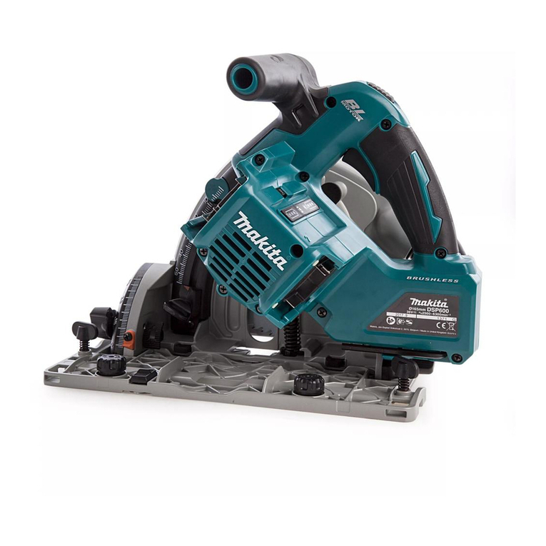
Makita SP6000 User manual

1
INSTRUCTION MANUAL
MANUEL D'INSTRUCTION
MANUAL DE INSTRUCCIONES
DOUBLE INSULATION
DOUBLE ISOLATION
DOBLE AISLAMIENTO
Plunge Cut Circular Saw
Scie circulaire plongeante
Sierra Circular de Inmersión
007654
SP6000
IMPORTANT: Read Before Using.
IMPORTANT: Lire avant usage.
IMPORTANTE: Leer antes de usar.

2
ENGLISH (Original instructions)
SPECIFICATIONS
Model SP6000
Blade diameter 165 mm (6-1/2")
at 90° 56 mm (2-3/16")
at 45° 40 mm (1-9/16")
Max. cutting depth
at 48° 38 mm (1-1/2")
No load speed (RPM) 2,000 - 5,800 /min
Overall length 341 mm (13-3/8")
Net weight 4.4 kg (9.7 lbs)
• Due to our continuing program of research and development, the specifications herein are subject to change without notice.
• Specifications may differ from country to country.
• Weight according to EPTA-Procedure 01/2003
GEA008-2
General Power Tool Safety Warnings
WARNING Read all safety warnings and all
instructions.
Failure to follow the warnings and instructions
may result in electric shock, fire and/or serious injury.
Save all warnings and
instructions for future reference.
The term "power tool" in the warnings refers to your
mains-operated (corded) power tool or battery-operated
(cordless) power tool.
Work area safety
1. Keep work area clean and well lit. Cluttered or
dark areas invite accidents.
2. Do not operate power tools in explosive
atmospheres, such as in the presence of
flammable liquids, gases or dust. Power tools
create sparks which may ignite the dust or fumes.
3. Keep children and bystanders away while
operating a power tool. Distractions can cause
you to lose control.
Electrical safety
4. Power tool plugs must match the outlet. Never
modify the plug in any way. Do not use any
adapter plugs with earthed (grounded) power
tools. Unmodified plugs and matching outlets will
reduce risk of electric shock.
5. Avoid body contact with earthed or grounded
surfaces such as pipes, radiators, ranges and
refrigerators. There is an increased risk of
electric shock if your body is earthed or grounded.
6. Do not expose power tools to rain or wet
conditions. Water entering a power tool will
increase the risk of electric shock.
7. Do not abuse the cord. Never use the cord for
carrying, pulling or unplugging the power tool.
Keep cord away from heat, oil, sharp edges or
moving parts. Damaged or entangled cords
increase the risk of electric shock.
8. When operating a power tool outdoors, use an
extension cord suitable for outdoor use. Use of
a cord suitable for outdoor use reduces the risk of
electric shock.
9. If operating a power tool in a damp location is
unavoidable, use a ground fault circuit
interrupter (GFCI) protected supply. Use of an
GFCI reduces the risk of electric shock.
Personal Safety
10.
Stay alert, watch what you are doing and use
common sense when operating a power tool. Do
not use a power tool while you are tired or under
the influence of drugs, alcohol or medication.
A
moment of inattention while operating power tools
may result in serious personal injury.
11. Use personal protective equipment. Always
wear eye protection. Protective equipment such
as dust mask, non-skid safety shoes, hard hat, or
hearing protection used for appropriate conditions
will reduce personal injuries.
12. Prevent unintentional starting. Ensure the
switch is in the off-position before connecting
to power source and/or battery pack, picking
up or carrying the tool. Carrying power tools
with your finger on the switch or energising power
tools that have the switch on invites accidents.
13. Remove any adjusting key or wrench before
turning the power tool on. A wrench or a key left
attached to a rotating part of the power tool may
result in personal injury.
14. Do not overreach. Keep proper footing and
balance at all times. This enables better control
of the power tool in unexpected situations.
15.
Dress properly. Do not wear loose clothing or
jewellery. Keep your hair, clothing, and gloves
away from moving parts.
Loose clothes, jewellery
or long hair can be caught in moving parts.

3
16.
If devices are provided for the connection of dust
extraction and collection facilities, ensure these
are connected and properly used.
Use of dust
collection can reduce dust-related hazards.
Power tool use and care
17. Do not force the power tool. Use the correct
power tool for your application. The correct
power tool will do the job better and safer at the
rate for which it was designed.
18.
Do not use the power tool if the switch does not turn
it on and off.
Any power tool that cannot be controlled
with the switch is dangerous and must be repaired.
19.
Disconnect the plug from the power source and/or
the battery pack from the power tool before making
any adjustments, changing accessories, or storing
power tools.
Such preventive safety measures reduce
the risk of starting the power tool accidentally.
20. Store idle power tools out of the reach of
children and do not allow persons unfamiliar
with the power tool or these instructions to
operate the power tool. Power tools are
dangerous in the hands of untrained users.
21. Maintain power tools. Check for misalignment
or binding of moving parts, breakage of parts
and any other condition that may affect the
power tool’s operation. If damaged, have the
power tool repaired before use. Many accidents
are caused by poorly maintained power tools.
22. Keep cutting tools sharp and clean. Properly
maintained cutting tools with sharp cutting edges
are less likely to bind and are easier to control.
23. Use the power tool, accessories and tool bits
etc. in accordance with these instructions,
taking into account the working conditions
and the work to be performed. Use of the power
tool for operations different from those intended
could result in a hazardous situation.
Service
24. Have your power tool serviced by a qualified
repair person using only identical replacement
parts. This will ensure that the safety of the power
tool is maintained.
25. Follow instruction for lubricating and
changing accessories.
26. Keep handles dry, clean and free from oil and
grease.
USE PROPER EXTENSION CORD. Make sure your
extension cord is in good condition. When using an
extension cord, be sure to use one heavy enough to
carry the current your product will draw. An undersized
cord will cause a drop in line voltage resulting in loss of
power and overheating. Table 1 shows the correct size
to use depending on cord length and nameplate ampere
rating. If in doubt, use the next heavier gage. The
smaller the gage number, the heavier the cord.
Table 1: Minimum gage for cord
Ampere Rating
Volts Total length of cord in feet
More Than Not More Than
120V 25 ft. 50 ft. 100 ft. 150 ft.
AWG
06
6
10
12
10
12
16
18
18
16
14
16 16 14
1416
16
12
14
12
12
Not Recommended
220V - 240V 50 ft. 100 ft. 200 ft. 300 ft.
000300
GEB126-1
CIRCULAR SAW SAFETY
WARNINGS
Cutting procedures
1. DANGER: Keep hands away from cutting
area and the blade. Keep your second hand on
auxiliary handle, or motor housing. If both
hands are holding the saw, they cannot be cut by
the blade.
2. Do not reach underneath the workpiece. The
guard cannot protect you from the blade below the
workpiece.
3. Adjust the cutting depth to the thickness of
the workpiece. Less than a full tooth of the blade
teeth should be visible below the workpiece.
4. Never hold piece being cut in your hands or
across your leg. Secure the workpiece to a
stable platform. It is important to support the
work properly to minimize body exposure, blade
binding, or loss of control.

4
A typical illustration of proper hand support, workpiece
support, and supply cord routing (if applicable).
000157
5.
Hold the power tool by insulated gripping
surfaces only, when performing an operation
where the cutting tool may contact hidden wiring
or its own cord.
Contact with a "live" wire will also
make exposed metal parts of the power tool "live" and
could give the operator an electric shock.
6. When ripping, always use a rip fence or
straight edge guide. This improves the accuracy
of cut and reduces the chance of blade binding.
7.
Always use blades with correct size and shape
(diamond versus round) of arbour holes.
Blades
that do not match the mounting hardware of the saw
will run eccentrically, causing loss of control.
8. Never use damaged or incorrect blade
washers or bolt. The blade washers and bolt
were specially designed for your saw, for optimum
performance and safety of operation.
Kickback causes and related warnings
−kickback is a sudden reaction to a pinched, bound or
misaligned saw blade, causing an uncontrolled saw to
lift up and out of the workpiece toward the operator;
−when the blade is pinched or bound tightly by the kerf
closing down, the blade stalls and the motor reaction
drives the unit rapidly back toward the operator;
−if the blade becomes twisted or misaligned in the cut,
the teeth at the back edge of the blade can dig into the
top surface of the wood causing the blade to climb out
of the kerf and jump back toward the operator.
Kickback is the result of saw misuse and/or incorrect
operating procedures or conditions and can be avoided
by taking proper precautions as given below.
9.
Maintain a firm grip with both hands on the saw and
position your arms to resist kickback forces. Position
your body to either side of the blade, but not in line
with the blade.
Kickback could cause the saw to jump
backwards, but kickback forces can be controlled by the
operator, if proper precautions are taken.
10.
When blade is binding, or when interrupting a cut for
any reason, release the trigger and hold the saw
motionless in the material until the blade comes to a
complete stop. Never attempt to remove the saw from
the work or pull the saw backward while the blade is
in motion or kickback may occur.
Investigate and take
corrective actions to eliminate the cause of blade binding.
11. When restarting a saw in the workpiece, centre
the saw blade in the kerf and check that saw
teeth are not engaged into the material. If saw
blade is binding, it may walk up or kickback from
the workpiece as the saw is restarted.
12. Support large panels to minimise the risk of
blade pinching and kickback. Large panels tend
to sag under their own weight. Supports must be
placed under the panel on both sides, near the
line of cut and near the edge of the panel.
To avoid kickback, do support
board or panel near the cut.
000154
Do not support board or
panel away from the cut.
000156
13.
Do not use dull or damaged blades.
Unsharpened
or improperly set blades produce narrow kerf causing
excessive friction, blade binding and kickback.
14.
Blade depth and bevel adjusting locking levers
must be tight and secure before making cut.
If
blade adjustment shifts while cutting, it may cause
binding and kickback.
15. Use extra caution when sawing into existing
walls or other blind areas. The protruding blade
may cut objects that can cause kickback.
16.
ALWAYS hold the tool firmly with both hands.
NEVER place your hand, leg or any part of your
body under the tool base or behind the saw,
especially when making cross-cuts.
If kickback
occurs, the saw could easily jump backwards over

5
your hand, leading to serious personal injury.
000194
17. Never force the saw. Push the saw forward at a
speed so that the blade cuts without slowing.
Forcing the saw can cause uneven cuts, loss of
accuracy, and possible kickback.
Guard function
18. Check guard for proper closing before each
use. Do not operate the saw if guard does not
move freely and enclose the blade instantly.
Never clamp or tie the guard so that the blade
is exposed. If saw is accidentally dropped, guard
may be bent. Check to make sure that guard
moves freely and does not touch the blade or any
other part, in all angles and depths of cut.
19.
Check the operation and condition of the guard
return spring. If the guard and the spring are not
operating properly, they must be serviced before
use.
Guard may operate sluggishly due to damaged
parts, gummy deposits, or a build-up of debris.
20.
Assure that the base plate of the saw will not shift
while performing the “plunge cut” when the blade
bevel setting is not at 90
゚
.
Blade shifting sideways
will cause binding and likely kick back.
21. Always observe that the guard is covering the
blade before placing saw down on bench or
floor. An unprotected, coasting blade will cause
the saw to walk backwards, cutting whatever is in
its path. Be aware of the time it takes for the blade
to stop after switch is released.
Additional safety warnings
22. Intended use
This tool is intended to cut wood products only.
23.
Use extra caution when cutting damp wood,
pressure treated lumber, or wood containing knots.
Maintain smooth advancement of tool without decrease
in blade speed to avoid overheating the blade tips.
24. Do not attempt to remove cut material when
blade is moving. Wait until blade stops before
grasping cut material.Blades coast after turn off.
25. Avoid cutting nails. Inspect for and remove all
nails from lumber before cutting.
26. Place the wider portion of the saw base on that
part of the workpiece which is solidly
supported, not on the section that will fall off
when the cut is made. As examples, Fig. 1
illustrates the RIGHT way to cut off the end of
a board, and Fig. 2 the WRONG way. If the
workpiece is short or small, clamp it down. DO
NOT TRY TO HOLD SHORT PIECES BY HAND!
Fig.1
000147
Fig.2
000150
27. Before setting the tool down after completing
a cut, be sure that the guard has closed and
the blade has come to a complete stop.
28. Never attempt to saw with the circular saw
held upside down in a vise. This is extremely
dangerous and can lead to serious accidents.
000029

6
29. Some material contains chemicals which may
be toxic. Take caution to prevent dust
inhalation and skin contact. Follow material
supplier safety data.
30. Do not stop the blades by lateral pressure on
the saw blade.
31. Do not use any abrasive wheels.
32. Only use the saw blade with the diameter that
is marked on the tool or specified in the
manual. Use of an incorrectly sized blade may
affect the proper guarding of the blade or guard
operation which could result in serious personal
injury.
33. Keep blade sharp and clean. Gum and wood
pitch hardened on blades slows saw and
increases potential for kickback. Keep blade clean
by first removing it from tool, then cleaning it with
gum and pitch remover, hot water or kerosene.
Never use gasoline.
34. Wear a dust mask and hearing protection
when use the tool.
SAVE THESE INSTRUCTIONS.
WARNING:
DO NOT let comfort or familiarity with product
(gained from repeated use) replace strict adherence
to safety rules for the subject product. MISUSE or
failure to follow the safety rules stated in this
instruction manual may cause serious personal
injury.
USD201-2
Symbols
The followings show the symbols used for tool.
・volts
・amperes
・hertz
・alternating current
・no load speed
・Class II Construction
・revolutions or reciprocation per minute
FUNCTIONAL DESCRIPTION
CAUTION:
• Always be sure that the tool is switched off and
unplugged before adjusting or checking function on
the tool.
Adjusting depth of cut
21
007656
CAUTION:
• After adjusting the depth of cut, always tighten the
clamping screw securely.
Loosen the clamping screw on the depth guide and
move the blade lower limit stopper to the desired depth
on the scale plate. At the desired depth of cut, tighten
the clamping screw firmly.
For cleaner, safer cuts, set cut depth so that no more
than one blade tooth projects below workpiece. Using
proper cut depth helps to reduce potential for dangerous
KICKBACKS which can cause personal injury.
NOTE:
• Setting the blade lower limit stopper to the desired
depth on the scale plate allows rough depth of cut.
For accurate depth of cut, measure the actual
protrusion of saw blade below the tool base.
Quick stop button for 2 to 3 mm depth of cut
when using guide rail (accessory)
1
007669
This tool has the quick stop button for 2 to 3 mm depth of
cut on the gear housing aside the rear handle when
using guide rail. This is used when avoiding splinter on
the workpiece in the cut. Make a pass of the 2 to 3 mm
first cut and then make another pass of usual cut.
To obtain the 2 to 3 mm depth of cut, push in the stop
button toward the saw blade. This is convenient for
avoiding splinter on the workpiece.
1. Quick stop
button
1. Clamping screw
2. Blade lower limit
stopper

7
To release the depth of cut from this position for free
depth of cut, just pull the button back.
1
007670
Bevel cutting
1
1
2
007657
Tilting to the right
1
007659
Turn the positive stopper so that the arrow on it points
one of two positions (vertical for 22.5°, horizontal for 45°).
Loosen the clamping screws in front and back. Then, tilt
the tool base until it stops and secure the base with the
clamping screws.
To get 48° bevel angle, move the lever to 48° marking as
far as it will go. Turn the positive stopper so that the
arrow on it points to the horizontal position. Then, tilt the
tool base until it stops and secure the base with the
clamping screws.
1
007660
Tilting to the left
1
007661
The tool can be tilted to the left 1° bevel angle. To get
the left 1° bevel angle, loosen the clamping screws in
front and back, tilt the tool handle slightly to the right and
push two bevel angle shifting levers at the same time in
the direction of arrow which has a marking -1. And then
tilt the tool handle to the left while pushing these two
levers at the same time. Secure the base with the
clamping screws.
NOTE:
• Returning the blade to the right angle makes the
shifting lever return to 0° by itself.
Sighting
12
A
B
007671
When using the tool without guide rail (accessory)
For straight cuts, align the A position on the front of the
base with your cutting line. For 45° bevel cuts, align the
B position with it.
When using the tool with guide rail (accessory)
For both straight cuts and 45° bevel cuts, always align
the A position on the front of the base with your cutting
line.
Switch action
1
2
007664
1. Lock-off button
2. Switch trigger
1. Base
2. Cutting line
1. Bevel angle
shifting lever
1. Lever
1. Positive stopper
1. Clamping
screws
2. Tool base
1. Quick stop
button

8
CAUTION:
• Before plugging in the tool, always check to see
that the switch trigger actuates properly and
returns to the "OFF" position when released.
To prevent the switch trigger from being accidentally
pulled, a lock-off button is provided. To start the tool,
push in the lock-off button and pull the switch trigger.
Release the switch trigger to stop.
Speed adjusting dial
1
007663
The tool speed can be adjusted by turning the adjusting
dial. Higher speed is obtained when the dial is turned in
the direction of number 6; lower speed is obtained when
it is turned in the direction of number 1.
Refer to the table to select the proper speed for the
workpiece to be cut. However, the appropriate speed
may differ with the type or thickness of the workpiece. In
general, higher speeds will allow you to cut workpieces
faster but the service life of the blade will be reduced.
Number min
-1
(RPM)
1
2
3
4
5
6
2,000
2,500
3,500
4,500
5,500
5,800
014993
CAUTION:
• The speed adjusting dial can be turned only as far
as 6 and back to 1. Do not force it past 6 or 1, or
the speed adjusting function may no longer work.
• The speed adjusting dial is not for using low speed
rated saw blades but for obtaining a speed which is
suitable to material of workpiece. Use only saw
blades which are rated for at least the maximum no
load speed stated in the SPECIFICATIONS.
The tools equipped with electronic function are easy to
operate because of the following features.
Overload protector
When the tool is overloaded and current flows above a
certain level, the tool automatically stops to protect
motor.
Constant speed control
Electronic speed control for obtaining constant speed.
Possible to get fine finish, because the rotating speed is
kept constant even under load condition.
Soft start feature
Soft start because of suppressed starting shock.
ASSEMBLY
CAUTION:
• Always be sure that the tool is switched off and
unplugged before carrying out any work on the
tool.
Hex wrench storage
1
007684
Hex wrench is stored on the tool. To remove hex wrench,
just pull it out.
To install hex wrench, place it on the grip and insert it as
far as it will go.
Removing or installing saw blade
CAUTION:
• Do not use saw blades which do not comply with
the characteristics specified in these instructions.
• Use only saw blades which are rated for at least
the maximum no load speed stated in the
SPECIFICATIONS.
• Be sure the blade is installed with teeth pointing up
at the front of the tool.
• Use only the Makita wrench to install or remove the
blade.
To remove the blade, push in the lock-off button to
unlock the upper limit stopper.
21
007662
Turn the locking lever to lock the saw head for replacing
a blade.
1. Lock-off button
2. Locking lever
1. Hex wrench
1. Speed adjusting
dial

9
1
007655
With the lock-off button depressed and the locking lever
turned, lower the handle so that the lock pin fits in the
groove formed by the locking lever and the depth guide
with scale plate. Make sure that the lock pin fits in the
groove.
Press the shaft lock fully so that the blade cannot
revolve and use the wrench to loosen the hex bolt
counterclockwise. Then remove the hex bolt, outer
flange and blade.
1
2
007658
To install the blade, follow the removal procedure in
reverse. BE SURE TO TIGHTEN THE HEX BOLT
CLOCKWISE SECURELY.
1
2
3
4
007672
When changing blade, make sure to also clean the
guard of accumulated sawdust as discussed in the
Maintenance section. Such efforts do not replace the
need to check guard operation before each use.
Dust bag (accessory)
CAUTION:
• Before use, make sure that the dust bag is
positioned so that it does not contact workpiece
during operation.
1
2
010505
To attach the dust bag, fit it onto the dust port. If the dust
bag becomes an obstacle to your work, turn the dust
port to change the dust bag position.
1
010506
When the dust bag is about half full, switch off and
unplug the tool. Remove the dust bag from the tool and
pull the bag's fastener out. Empty the dust bag by
tapping it lightly to remove as much of the dust as
possible.
Connecting a vacuum cleaner
1
2
007673
When you wish to perform clean cutting operation,
connect a Makita vacuum cleaner to your tool. Connect
a hose of the vacuum cleaner to the dust port as shown
in the figure.
1. Vacuum cleaner
2. Dust port
1. Fastener
1. Dust port
2. Dust bag
1. Hex bolt
2. Outer flange
3. Saw blade
4. Inner flange
1. Hex wrench
2. Shaft lock
1. Locking lever

10
OPERATION
Section cutting (ordinary sawing)
CAUTION:
• Be sure to move the tool forward in a straight line
gently. Forcing or twisting the tool will result in
overheating the motor and dangerous kickback,
possibly causing severe injury.
• Never approach any part of your body under the
tool base when section cutting, especially at
starting. Doing so may cause serious personal
injuries. The blade is exposed under the tool base.
Hold the tool firmly. The tool is provided with both a front grip
and rear handle. Use both to best grasp the tool. If both hands
are holding saw, they cannot be cut by the blade. Set the front
of base on the workpiece to be cut without the blade making
any contact. Then push in the lock-off button and turn the tool
on and wait until the blade attains full speed. Now press down
the saw head slowly to the preset depth of cut and simply move
the tool forward over the workpiece surface, keeping it flat and
advancing smoothly until the sawing is completed.
To get clean cuts, keep your sawing line straight and your
speed of advance uniform. If the cut fails to properly follow your
intended cut line, do not attempt to turn or force the tool back to
the cut line. Doing so may bind the blade and lead to dangerous
kickback and possible serious injury. Release switch, wait for
blade to stop and then withdraw tool. Realign tool on new cut
line, and start cut again. Attempt to avoid positioning which
exposes operator to chips and wood dust being ejected from
saw. Use eye protection to help avoid injury.
007674
When using with guide rail (accessory)
1
007685
Place the tool on the rear end of guide rail. Turn two adjusting
screws on the tool base so that the tool slides smoothly without
a clatter. Hold the tool firmly. The tool is provided with both a
front grip and rear handle. Use both to best grasp the tool. Turn
on the tool, press down the tool to the preset depth of cut and
cut the splinterguard along the full length with a stroke. The
edge of the splinterguard corresponds to the cutting edge.
When bevel cutting with the guide rail, slide the slide
lever on the tool base so that the tool does not fall down
on its side.
1
007666
Move the slide lever on the tool base in the direction of
arrow so that it engages the undercut groove in the
guide rail.
Rip fence (guide rule) (Accessory)
1
007675
The handy rip fence allows you to do extra-accurate
straight cuts. Simply slide the rip fence up snugly against
the side of the workpiece and secure it in position with
the screws on the front and the back of the base. It also
makes repeated cuts of uniform width possible.
Overturning the rip fence (guide rule) also works as a
sub base for the tool.
Plunge cutting (Cutting-out)
1
2
007686
WARNING:
• To avoid a kickback, be sure to observe the
following instructions.
When using the tool without guide rail
Place the tool on the workpiece with the rear edge of tool
base against a fixed stop or equivalent which is devised
by an operator.
1. Rear edge of
tool base
2. Fixed stop
1. Rip fence (Guide
rule)
1. Slide lever
1. Adjusting screws

11
When using the tool with guide rail
Place the tool on the guide rail with the rear edge of tool
base against a fixed stop or equivalent which is clamped
on the guide rail.
Hold the tool firmly with one hand on the front grip and
the other on the tool handle. Then push in the lock-off
button and turn the tool on and wait until the blade
attains full speed. Now press down the saw head slowly
to the preset depth of cut and simply move the tool
forward to the desired plunge position.
NOTE:
• The markings on the side of the blade guard show
the absolute front and the absolute rear cutting
points of the saw blade (A for diameter 160 mm
and B for diameter 165 mm) at the maximum
cutting depth and using the guide rail.
B
AA
B
007678
Guide device (accessories)
Use of the miter gauge (accessory) allows exact miter
cuts with angles and fitting works.
Use of the clamp (accessory) ensures firm hold of
workpiece on the table.
MAINTENANCE
CAUTION:
• Always be sure that the tool is switched off and
unplugged before attempting to perform inspection
or maintenance.
• Clean out the guard to ensure there is no
accumulated sawdust which may impede the
operation of the guarding system. A dirty
guarding system may limit the proper operation
which could result in serious personal injury. The
most effective way to accomplish this cleaning is
with compressed air. If the dust is being blown
out of the guard be sure the proper eye and
breathing protection is used.
• Never use gasoline, benzine, thinner, alcohol or
the like. Discoloration, deformation or cracks may
result.
Adjusting for accuracy of 90° and 45° cut
(vertical and 45° cut)
This adjustment has been made at the factory. But if it is
off, adjust the adjusting screws with a hex wrench while
inspecting 90° or 45° the blade with the base using a
triangular rule or square rule, etc.
1
007667
1
007668
NOTE:
• Adjusting for accuracy of 22.5° , 48° and -1° cut
cannot be performed.
Replacing carbon brushes
1
001145
Remove and check the carbon brushes regularly.
Replace when they wear down to the limit mark. Keep
the carbon brushes clean and free to slip in the holders.
Both carbon brushes should be replaced at the same
time. Use only identical carbon brushes.
Use a screwdriver to remove the brush holder caps.
Take out the worn carbon brushes, insert the new ones
and secure the brush holder caps.
1. Limit mark
1. Adjusting screw
for 45 ゚
1. Adjusting screw
for 90 ゚

12
1
2
007676
To maintain product SAFETY and RELIABILITY, repairs,
any other maintenance or adjustment should be
performed by Makita Authorized Service Centers,
always using Makita replacement parts.
OPTIONAL ACCESSORIES
CAUTION:
• These accessories or attachments are
recommended for use with your Makita tool
specified in this manual. The use of any other
accessories or attachments might present a risk of
injury to persons. Only use accessory or
attachment for its stated purpose.
If you need any assistance for more details regarding
these accessories, ask your local Makita Service Center.
• Saw blades
• Guide rail
• Rip fence (Guide rule)
• Miter gauge
• Clamp
• Hex wrench
• Sheet set for guide rail
• Rubber sheet set for guide rail
• Position sheet set for guide rail
• Dust bag assembly
NOTE:
• Some items in the list may be included in the tool
package as standard accessories. They may differ
from country to country.
MAKITA LIMITED ONE YEAR WARRANTY
Warranty Policy
Every Makita tool is thoroughly inspected and tested
before leaving the factory. It is warranted to be free of
defects from workmanship and materials for the period
of ONE YEAR from the date of original purchase.
Should any trouble develop during this one year period,
return the COMPLETE tool, freight prepaid, to one of
Makita’s Factory or Authorized Service Centers. If
inspection shows the trouble is caused by defective
workmanship or material, Makita will repair (or at our
option, replace) without charge.
This Warranty does not apply where:
IN NO EVENT SHALL MAKITA BE LIABLE FOR ANY
INDIRECT, INCIDENTAL OR CONSEQUENTIAL
DAMAGES FROM THE SALE OR USE OF THE
PRODUCT. THIS DISCLAIMER APPLIES BOTH
DURING AND AFTER THE TERM OF THIS
WARRANTY.
MAKITA DISCLAIMS LIABILITY FOR ANY IMPLIED
WARRANTIES, INCLUDING IMPLIED WARRANTIES
OF "MERCHANTABILITY" AND "FITNESS FOR A
SPECIFIC PURPOSE," AFTER THE ONE YEAR TERM
OF THIS WARRANTY.
This Warranty gives you specific legal rights, and you
may also have other rights which vary from state to
state. Some states do not allow the exclusion or
limitation of incidental or consequential damages, so
the above limitation or exclusion may not apply to you.
Some states do not allow limitation on how long an
implied warranty lasts, so the above limitation may not
apply to you.
repairs have been made or attempted by others:
repairs are required because of normal wear and
tear:
the tool has been abused, misused or improperly
maintained:
alterations have been made to the tool.
EN0006-1
1. Screwdriver
2. Brush holder
cap

13
FRANÇAIS (Mode d’emploi original)
SPÉCIFICATIONS
Modèle SP6000
Diamètre de la lame 165 mm (6-1/2")
à 90° 56 mm (2-3/16")
à 45° 40 mm (1-9/16")
Profondeur de coupe max.
à 48° 38 mm (1-1/2")
Vitesse à vide (T/MIN) 2 000 – 5 800 /min
Longueur totale 341 mm (13-3/8")
Poids net 4,4 kg (9,7 lbs)
• Étant donné l'évolution constante de notre programme de recherche et de développement, les spécifications contenues dans ce
manuel sont sujettes à modification sans préavis.
• Les spécifications peuvent varier suivant les pays.
• Poids conforme à la procédure EPTA du 01/2003
GEA008-2
Consignes de sécurité générales
pour outils électriques
MISE EN GARDE Veuillez lire toutes les mises en
garde de sécurité et toutes les instructions.
L'ignorance
des mises en garde et des instructions comporte un risque de
choc électrique, d'incendie et/ou de blessure grave.
Conservez toutes les mises en
garde et instructions pour
référence future.
Le terme ≪outil électrique ≫qui figure dans les
avertissements fait référence à un outil électrique
branché sur une prise de courant (par un cordon
d'alimentation) ou alimenté par batterie (sans fil).
Sécurité de la zone de travail
1. Maintenez la zone de travail propre et bien
éclairée. Les zones de travail encombrées ou
sombres ouvrent grande la porte aux accidents.
2. N'utilisez pas les outils électriques dans les
atmosphères explosives, par exemple en
présence de liquides, gaz ou poussières
inflammables. Les outils électriques produisent
des étincelles au contact desquelles la poussière
ou les vapeurs peuvent s'enflammer.
3. Assurez-vous qu'aucun enfant ou curieux ne
s'approche pendant que vous utilisez un outil
électrique. Vous risquez de perdre la maîtrise de
l'outil si votre attention est détournée.
Sécurité en matière d'électricité
4. Les fiches d'outil électrique sont conçues
pour s'adapter parfaitement aux prises de
courant. Ne modifiez jamais la fiche de
quelque façon que ce soit. N'utilisez aucun
adaptateur de fiche sur les outils électriques
avec mise à la terre. En ne modifiant pas les
fiches et en les insérant dans des prises de
courant pour lesquelles elles ont été conçues
vous réduirez les risques de choc électrique.
5. Évitez tout contact corporel avec les surfaces
mises à la terre, telles que les tuyaux,
radiateurs, cuisinières et réfrigérateurs. Le
risque de choc électrique est plus élevé si votre
corps se trouve mis à la terre.
6. N'exposez pas les outils électriques à la pluie
ou à l'eau. La présence d'eau dans un outil
électrique augmente le risque de choc électrique.
7.
Ne maltraitez pas le cordon. N'utilisez jamais le
cordon pour transporter, tirer ou débrancher
l'outil électrique. Maintenez le cordon à l'écart des
sources de chaleur, de l'huile, des objets à bords
tranchants et des pièces en mouvement.
Le risque
de choc électrique est plus élevé lorsque les cordons
sont endommagés ou enchevêtrés.
8. Lorsque vous utilisez un outil électrique à
l'extérieur, utilisez un cordon prolongateur
prévu à cette fin. Les risques de choc électrique
sont moindres lorsqu'un cordon conçu pour
l'extérieur est utilisé.
9. Si vous devez utiliser un outil électrique dans
un endroit humide, utilisez une source
d'alimentation protégée par un disjoncteur de
fuite à la terre. L'utilisation d'un disjoncteur de
fuite à la terre réduit le risque de choc électrique.
Sécurité personnelle
10. Restez alerte, attentif à vos mouvements et
faites preuve de bon sens lorsque vous
utilisez un outil électrique. Évitez d'utiliser un
outil électrique si vous êtes fatigué ou si vous
avez pris une drogue, de l'alcool ou un
médicament. Un moment d'inattention pendant
l'utilisation d'un outil électrique peut entraîner une
grave blessure.

14
11. Portez des dispositifs de protection
personnelle. Portez toujours un protecteur
pour la vue. Les risques de blessure seront
moins élevés si vous utilisez des dispositifs de
protection tels qu'un masque antipoussières, des
chaussures à semelle antidérapante, une coiffure
résistante ou une protection d'oreilles.
12.
Évitez les démarrages accidentels. Assurez-vous
que l'interrupteur est en position d'arrêt avant de
brancher l'outil et/ou d'insérer la batterie, ainsi
qu'avant de saisir ou de transporter l'outil.
Vous
ouvrez la porte aux accidents si vous transportez les
outils électriques avec le doigt sur l'interrupteur ou
laissez l'interrupteur en position de marche avant de
mettre l'outil sous tension.
13. Retirez toute clé de réglage ou de serrage
avant de mettre l'outil sous tension. Toute clé
laissée en place sur une pièce rotative de l'outil
électrique peut entraîner une blessure.
14. Maintenez une bonne position. Assurez-vous
d'une bonne prise au sol et d'une bonne
position d'équilibre en tout temps. Cela vous
permettra d'avoir une meilleure maîtrise de l'outil
dans les situations imprévues.
15. Portez des vêtements adéquats. Ne portez ni
vêtements amples ni bijoux. Vous devez
maintenir cheveux, vêtements et gants à
l'écart des pièces en mouvement. Les pièces
en mouvement peuvent happer les vêtements
amples, les bijoux et les cheveux longs.
16. Si des accessoires sont fournis pour
raccorder un appareil d'aspiration et de
collecte de la poussière, assurez-vous qu'ils
sont correctement raccordés et qu'ils sont
utilisés de manière adéquate. L'utilisation d'un
appareil d'aspiration permet de réduire les risques
liés à la présence de poussière dans l'air.
Utilisation et entretien des outils électriques
17. Ne forcez pas l'outil électrique. Utilisez l'outil
électrique adéquat suivant le type de travail à
effectuer. Si vous utilisez l'outil électrique
adéquat et respectez le régime pour lequel il a été
conçu, il effectuera un travail de meilleure qualité
et de façon plus sécuritaire.
18.
N'utilisez pas l'outil électrique s'il n'est pas possible
de mettre sa gâchette en position de marche et
d'arrêt.
Un outil électrique dont l'interrupteur est
défectueux représente un danger et doit être réparé.
19.
Débranchez la fiche de la source d'alimentation
et/ou retirez le bloc-piles de l'outil électrique avant
d'effectuer tout réglage, de changer un accessoire
ou de ranger l'outil électrique.
De telles mesures
préventives réduisent les risques de démarrage
accidentel de l'outil électrique.
20. Après l'utilisation d'un outil électrique,
rangez-le hors de portée des enfants et ne
laissez aucune personne l'utiliser si elle n'est
pas familiarisée avec l'outil électrique ou les
présentes instructions d'utilisation. Les outils
électriques représentent un danger entre les
mains de personnes qui n'en connaissent pas le
mode d'utilisation.
21. Veillez à l’entretien des outils électriques.
Assurez-vous que les pièces mobiles ne sont
pas désalignées ou coincées, qu’aucune pièce
n’est cassée et que l’outil électrique n’a subi
aucun dommage affectant son bon
fonctionnement. Le cas échéant, faites réparer
l'outil électrique avant de l'utiliser. De
nombreux accidents sont causés par des outils
électriques mal entretenus.
22. Maintenez les outils tranchants bien aiguisés
et propres. Un outil tranchant dont l'entretien est
effectué correctement et dont les bords sont bien
aiguisés risquera moins de se coincer et sera plus
facile à maîtriser.
23. Utilisez l'outil électrique, ses accessoires, ses
embouts, etc., en respectant les présentes
instructions, en tenant compte des conditions
de travail et du type de travail à effectuer.
L'utilisation d'un outil électrique à des fins autres
que celles prévues peut entraîner une situation
dangereuse.
Réparation
24. Faites réparer votre outil électrique par un
réparateur qualifié qui utilise des pièces de
rechange identiques aux pièces d'origine. Le
maintien de la sûreté de l'outil électrique sera
ainsi assuré.
25. Suivez les instructions de lubrification et de
changement des accessoires.
26. Maintenez les poignées de l'outil sèches,
propres et exemptes d'huile ou de graisse.
UTILISEZ UN CORDON PROLONGATEUR
APPROPRIÉ. Assurez-vous que votre cordon
prolongateur est en bonne condition. Lorsque vous
utilisez un cordon prolongateur, assurez-vous qu'il est
assez robuste pour transporter le courant exigé par le
produit. Un cordon qui est trop petit entraînera une
baisse dans la tension composée, ce qui causera une
perte d'énergie et un surchauffage. Le tableau 1 indique
la dimension de cordon à utiliser, en fonction de la
longueur du cordon et de l'intensité nominale figurant
sur la plaque signalétique. En cas de doute, utilisez un
cordon plus robuste. Plus le numéro de calibre est bas,
plus le cordon est robuste.

15
Tableau 1. Gabarit minimum du cordon
Intensité nominale
Volts
Longueur totale du cordon en pieds
Plus de Pas plus de
120V 25 pi 50 pi 100 pi 150 pi
Calibre américain des fils
06
6
10
12
10
12
16
18
18
16
14
16 16 14
1416
16
12
14
12
12
Non recommandé
220V - 240V 50 pi 100 pi 200 pi 300 pi
000300
GEB126-1
CONSIGNES DE SÉCURITÉ
POUR LA SCIE CIRCULAIRE
Procédures de coupe
1. DANGER : N’approchez pas les mains de
la zone de coupe ou de la lame. Gardez l’autre
main sur la poignée auxiliaire ou sur le carter
du moteur. En tenant la scie avec vos deux
mains, vous mettez celles-ci à l’abri de la lame.
2. N'étendez pas la main sous la pièce. Le
protecteur ne peut pas vous protéger contre la
lame sous la pièce.
3. Ajustez la profondeur de coupe en fonction de
l'épaisseur de la pièce. La partie de la lame
visible sous la pièce doit être inférieure à une dent
de lame complète.
4. Ne maintenez jamais le matériau à scier dans
vos mains ou sur votre jambe. Immobilisez la
pièce sur une surface stable. Il est important de
soutenir adéquatement la pièce afin de minimiser
l'exposition du corps, les coincements de lame ou
les pertes de maîtrise.
Illustration de la façon typique et correcte de tenir la scie,
de soutenir la pièce et de placer le cordon.
000157
5. Tenez uniquement l’outil électrique par ses
surfaces de prise isolées pendant toute
opération où l’outil de coupe pourrait venir en
contact avec un câblage dissimulé ou avec
son propre cordon. En cas de contact avec un
conducteur sous tension, les pièces métalliques à
découvert de l’outil deviendraient également sous
tension et risqueraient de transmettre une
décharge à l’utilisateur.
6. Lors du sciage en long, utilisez toujours un
garde parallèle ou un guide de coupe
rectiligne. Cela améliore la précision de la coupe
et réduit le risque de coincement de la lame.
7.
Employez toujours une lame de diamètre
approprié et dont le trou central est de forme
correcte (angulaire ou ronde).
Une lame dont le trou
ne correspond pas à la forme du moyeu de fixation de
la scie risque de tourner de façon excentrique et de
vous faire perdre la maîtrise de l'outil.
8. N'utilisez jamais de rondelles ou boulons
endommagés ou inadéquats pour fixer la lame.
Les rondelles et le boulon ont été conçus
spécialement pour votre scie, afin d'assurer un
fonctionnement optimal et un travail sécuritaire.
Causes du recul et avertissements connexes
−le recul est une réaction soudaine survenant
lorsque la lame, coincée, pincée ou mal alignée
devient incontrôlable, se soulève hors de la pièce
et se dirige vers l'utilisateur ;
−lorsque la lame se trouve coincée ou pincée par le
trait de scie qui se referme sur elle, elle se bloque
et une réaction du moteur entraîne alors l'outil
rapidement vers l'utilisateur ;
−si la lame se tord ou se désaligne par rapport à la
ligne de coupe, les dents arrière risquent de
s'enfoncer dans la surface du bois et la lame de
quitter le trait de scie en reculant brusquement
vers l'utilisateur.
Le recul est le résultat d'une utilisation inadéquate de la
scie et/ou de procédures ou conditions d'utilisation
incorrectes ; on peut l'éviter en prenant des précautions
adéquates, indiquées ci-dessous.

16
9. Maintenez une prise ferme à deux mains sur la
scie, et placez vos bras de manière à pouvoir
résister à la force exercée lors des reculs.
Posez votre corps d'un côté ou de l'autre de la
lame, jamais dans sa ligne de coupe. Un recul
peut faire sauter la scie vers l'arrière, mais
l'utilisateur pourra maîtriser la force exercée par
ce recul s'il prend les précautions nécessaires.
10. Lorsque la lame se coince ou lorsque vous
interrompez la coupe pour une raison
quelconque, libérez la gâchette et gardez la
scie immobile dans le matériau jusqu'à ce que
la lame s'arrête parfaitement. N'essayez jamais
de retirer la scie de la pièce ou de faire reculer
la scie pendant que la lame tourne, autrement
il y a risque de choc recul. Identifiez la cause du
coincement de la lame et prenez les mesures
correctives pour éliminer le problème.
11. Avant de faire redémarrer la scie dans la pièce,
centrez la lame dans le trait de scie et
assurez-vous que les dents de la lame ne
mordent pas déjà dans le matériau. Si la lame
est coincée, elle risque de remonter dans le trait
de scie ou de causer un recul au moment du
redémarrage de la scie.
12. Les grands panneaux doivent être soutenus
pour minimiser les risques de recul causé par
le coincement de la lame. Les grands panneaux
ont tendance à s'affaisser sous leur propre poids.
Des supports doivent être installés sous le
panneau, des deux côtés, près de la ligne de
coupe et près du bord du panneau.
Pour éviter la rétroaction, supporter la planche
ou le panneau près de la ligne de coupe.
000154
Ne pas supporter la planche ou le panneau de
façon éloignée de la ligne de coupe.
000156
13. N'utilisez jamais les lames émoussées ou
endommagées. Les lames mal affûtées ou mal
avoyées produisent un trait de scie étroit qui
donne lieu à un frottement excessif, au
coincement de la lame et à un recul.
14.
Avant d'effectuer la coupe, les leviers de
verrouillage de la profondeur de coupe et de la
coupe en biseau doivent être fermement serrés.
Il y a risque de pincement et de recul si les réglages
de la lame se modifient pendant coupe.
15. Soyez particulièrement prudent lors des
coupes dans une cloison existante ou tout
autre matériau dont l’arrière n'est pas visible.
La lame pourrait rencontrer un objet dur, ce qui
provoquerait un recul.
16.
Tenez TOUJOURS l'outil fermement à deux mains.
Ne placez JAMAIS une main, une jambe ou toute
autre partie du corps sous la base de l'outil ou
derrière la scie, et ce tout particulièrement lors
des coupes en travers.
En cas de recul, la scie peut
facilement bondir vers l'arrière et vous blesser
gravement en passant sur votre main.
000194
17. Ne forcez jamais la scie. Poussez la scie vers
l’avant à une vitesse permettant à la lame de
couper sans ralentir. Le fait de forcer la scie
peut causer une coupe inégale, une perte de
précision ou un recul.

17
Fonctionnement du protecteur
18. Avant chaque utilisation, assurez-vous que le
protecteur se referme correctement. N’utilisez
pas la scie si le protecteur ne se déplace pas
librement et ne recouvre pas instantanément
la lame. Ne bloquez jamais le protecteur pour
le tenir en position ouverte (lame exposée). Si
la scie tombe par terre accidentellement, le
protecteur peut être gauchi. Assurez-vous que le
protecteur se déplace librement et qu’il ne touche
pas la lame ou tout autre élément de l’outil, quels
que soient les réglages d’angle et de profondeur
de coupe.
19. Vérifiez l'état et le bon fonctionnement du
ressort de rappel du protecteur. Si le
protecteur ou son ressort ne fonctionnent pas
correctement, il faut les réparer avant d'utiliser
l'outil. Le protecteur peut être lent à se refermer à
cause de pièces endommagées, de dépôts
collants ou d'une accumulation de débris.
20. Assurez-vous que la plaque d’appui de la scie
ne se déplace pas pendant l’exécution d’une «
coupe en plongée » lorsque l’angle de coupe
en biseau n’est pas réglé sur 90 ゚.Si la lame se
déplace de côté elle risque de se coincer et de
causer un recul.
21. Avant de déposer la scie sur l'établi ou le
plancher, assurez-vous que le protecteur
recouvre la lame. Sans protection et en roue
libre, la scie reculera en coupant tout sur son
passage. N'oubliez pas qu'il faut un certain temps
avant que la lame cesse de tourner une fois
l'interrupteur relâché.
Consignes de sécurité supplémentaires
22. Utilisation prévue
Cet outil est destiné à la coupe de produits de
bois uniquement.
23. Redoublez de prudence lorsque vous coupez
du bois humide, du bois traité sous pression
ou du bois qui contient des nœuds. Adoptez
une vitesse de coupe de telle sorte que l'outil
continue d'avancer en douceur, sans que la
vitesse de la lame ne diminue, pour éviter la
surchauffe de la pointe de la lame.
24. N’essayez pas de retirer le matériau coupé
pendant que la lame tourne. Attendez que la
lame s’arrête avant de retirer le matériau
coupé.Les lames tournent en roue libre après la
mise hors tension.
25. Prenez garde aux clous lors de la coupe. Avant
la coupe, vérifiez la présence de clous dans le
bois et retirez-les le cas échéant.
26. Placez la base de la scie sur la partie de la
pièce qui est solidement soutenue, non sur
celle qui tombera une fois la coupe terminée.
À titre d'exemples, la Fig. 1 illustre la BONNE
façon de couper l'extrémité d'une planche,
tandis que la Fig. 2 illustre la MAUVAISE façon
de procéder. Si la pièce est courte ou petite,
installez-la dans un dispositif de serrage.
N'ESSAYEZ PAS DE TENIR LES COURTES
PIÈCES UNIQUEMENT AVEC LA MAIN !
Fig.1
000147
Fig.2
000150
27.
Avant de déposer l'outil une fois la coupe
terminée, assurez-vous que le protecteur est
fermé et que la lame est complètement arrêtée.
28.
Ne tentez jamais de scier en plaçant la scie la tête
en bas dans un étau. Cela est très dangereux et
peut entraîner de graves accidents.
000029

18
29. Certains matériaux contiennent des produits
chimiques qui peuvent être toxiques. Prenez
les précautions nécessaires pour éviter
l'inhalation de ces poussières ou leur contact
avec la peau. Conformez-vous aux consignes
de sécurité du fournisseur du matériau.
30. N'appliquez jamais une pression latérale sur la
lame pour l'arrêter.
31. N'utilisez aucune meule abrasive.
32. N'utilisez que la lame dont le diamètre
correspond aux indications données sur l’outil
ou dans le manuel. L’utilisation d’une lame d’une
taille incorrecte peut affecter la protection de la
lame ou le fonctionnement du protecteur et cela
pourrait causer de graves blessures.
33. Maintenez la lame affûtée et propre. Les dépôts
de colle et les copeaux de bois durcis sur la lame
ralentissent la scie et augmentent les risques de
recul. Pour nettoyer la lame, retirez-la d’abord de
l’outil, puis utilisez un décapant, de l’eau chaude
ou du kérosène pour retirer la colle et les copeaux.
N’utilisez jamais d’essence.
34.
Portez un masque antipoussières et des
protections d'oreilles lorsque vous utilisez l'outil.
CONSERVEZ CE MODE
D'EMPLOI.
AVERTISSEMENT:
NE VOUS LAISSEZ PAS tromper (au fil d'une
utilisation répétée) par un sentiment d'aisance ou de
familiarité avec le produit en négligeant les
consignes de sécurité qui accompagnent le produit.
L'utilisation non sécuritaire ou incorrecte de cet outil
comporte un risque de blessure grave.
USD201-2
Symboles
Les symboles utilisés pour l'outil sont indiqués
ci-dessous.
・volts
・ampères
・hertz
・courant alternatif
・vitesse à vide
・construction, catégorie II
・tours ou alternances par minute
DESCRIPTION DU
FONCTIONNEMENT
ATTENTION:
• Assurez-vous toujours que l'outil est hors tension
et débranché avant de l'ajuster ou de vérifier son
fonctionnement.
Réglage de la profondeur de coupe
21
007656
ATTENTION:
• Après avoir ajusté la profondeur de coupe, serrez
toujours fermement la vis de serrage.
Desserrez la vis de serrage sur le guide de profondeur
et déplacez la butée de limite inférieure de la lame
jusqu'à la profondeur désirée sur la plaque graduée. À la
profondeur de coupe désirée, serrez fermement la vis de
serrage.
Pour obtenir des coupes plus propres et sans danger,
réglez la profondeur de coupe de sorte que pas plus
d'une dent de lame ne dépasse sous la pièce.
L'utilisation d'une profondeur de coupe adéquate aide à
réduire les risques de chocs en retour dangereux qui
peuvent causer des blessures.
NOTE:
• Le réglage de la butée de limite inférieure de la
lame à la profondeur de coupe désirée sur la
plaque graduée permet d'obtenir
approximativement ladite profondeur de coupe.
Pour une profondeur de coupe précise, mesurez la
partie saillante de la lame sous la base de l'outil.
Touche d'arrêt rapide pour une profondeur de
coupe de 2 à 3 mm lors de l'utilisation du
rail-guide (accessoire)
1
007669
1. Bouton d’arrêt
rapide
1. Vis de serrage
2. Butée de limite
inférieure de la
lame

19
Cet outil est équipé d'un bouton d'arrêt rapide pour une
profondeur de 2 à 3 mm lors de l'utilisation du rail-guide ;
ce bouton se trouve sur le carter d'engrenage, à côté de
la poignée arrière. Il sert à éviter de fendre la pièce lors
de la coupe. Faites d'abord une passe avec une
profondeur de coupe de 2 à 3 mm, puis une autre passe
ordinaire.
Pour obtenir une profondeur de coupe de 2 à 3 mm,
enfoncez le bouton d'arrêt vers la lame. Cela est
pratique pour éviter de fendre la pièce.
Pour libérer la lame de cette profondeur de coupe et
effectuer une coupe de profondeur libre, ramenez
simplement le bouton vers l'arrière.
1
007670
Coupe en biseau
1
1
2
007657
Inclinaison vers la droite
1
007659
Tournez le butoir positif de sorte que sa flèche pointe
vers l'une ou l'autre des deux positions (verticale pour
22.5°, horizontale pour 45°). Desserrez les vis de
serrage à l'avant et à l'arrière. Ensuite, inclinez la base
de l'outil jusqu'à ce qu'elle s'arrête et fixez-la à l'aide des
vis de serrage.
Pour obtenir un angle de coupe en biseau de 48°,
déplacez le levier sur le symbole 48°, le plus loin
possible. Tournez le butoir positif de sorte que sa flèche
pointe vers la position horizontale. Ensuite, inclinez la
base de l'outil jusqu'à ce qu'elle s'arrête et fixez-la à
l'aide des vis de serrage.
1
007660
Inclinaison vers la gauche
1
007661
L’outil peut être incliné sur l’angle de coupe en biseau gauche
de 1°. Pour obtenir l’angle de coupe en biseau gauche de 1°,
desserrez les vis de serrage à l’avant et à l’arrière, inclinez la
poignée de l’outil légèrement vers la droite et poussez les
deux leviers de changement d’angle de coupe en biseau en
même temps dans le sens de la flèche qui porte le symbole -1.
Inclinez ensuite la poignée de l’outil sur la gauche tout en
poussant ces deux leviers en même temps. Fixez la base
avec les vis de serrage.
NOTE:
• Si vous remettez la lame sur l'angle de droite, le
levier de changement d'angle retournera de
lui-même sur l'angle 0°.
Visée
12
A
B
007671
Lors de l'utilisation de l'outil sans le rail-guide
(accessoire)
Pour les coupes rectilignes, alignez sur la ligne de coupe la
position A à l'avant de la base. Pour les coupes en biseau de
45°, alignez la position B sur la ligne de coupe.
Lors de l'utilisation de l'outil avec le rail-guide
(accessoire)
Pour les coupes rectilignes et les coupes en biseau de
45°, alignez toujours sur votre ligne de coupe la position
A à l'avant de la base.
1. Base
2. Ligne de coupe
1. Levier de
changement
d’angle de
coupe en biseau
1. Levier
1. Butoir positif
1. Vis de serrage
2. Base de l’outil
1. Bouton d’arrêt
rapide

20
Interrupteur
1
2
007664
ATTENTION:
• Avant de brancher l'outil, assurez-vous toujours
que la gâchette fonctionne correctement et revient
en position d'arrêt une fois relâchée.
Un bouton de sécurité est fourni pour prévenir la
pression accidentelle sur la gâchette. Pour faire
démarrer l'outil, appuyez sur le bouton de sécurité puis
sur la gâchette. Pour l'arrêter, relâchez la gâchette.
Cadran de rélage de vitesse
1
007663
La vitesse de l’outil peut être réglée à l’aide du cadran
de réglage. Une vitesse plus élevée s’obtient en
tournant le cadran vers le numéro 6, et une vitesse plus
basse en le tournant vers le numéro 1.
Référez-vous au tableau pour sélectionner la vitesse qui
convient à la pièce à couper. La vitesse adéquate peut
toutefois varier suivant le type de matériau ou
l'épaisseur de la pièce. En général, les vitesses rapides
permettent de couper les pièces plus rapidement, mais
cela réduit la durée de service de la lame.
Numéro min
-1
(RPM)
1
2
3
4
5
6
2 000
2 500
3 500
4 500
5 500
5 800
014993
ATTENTION:
• Le cadran de réglage de la vitesse ne peut pas
dépasser le 6 et le 1. Ne le forcez pas à dépasser
le 6 ou le 1, sinon la fonction de réglage de la
vitesse risque de ne plus fonctionner.
• Le cadran de réglage de la vitesse n’a pas été
prévu pour l’utilisation de lames basse vitesse,
mais pour obtenir une vitesse adaptée au matériau
de la pièce à scier. Utilisez seulement des lames
dont la vitesse nominale correspond au moins à la
vitesse à vide maximale indiquée dans les
CARACTÉRISTIQUES TECHNIQUES.
Les caractéristiques qui suivent facilitent l'utilisation des
outils munis de fonctions électroniques.
Disjoncteur de surcharge
Lorsque l'outil est soumis à une surcharge et que le
courant dépasse un certain niveau, l'outil s'arrête
automatiquement pour protéger son moteur.
Commande de vitesse constante
Commande électronique de la vitesse afin d'obtenir une
vitesse constante. Permet d'obtenir une finition précise
puisque la vitesse de rotation est maintenue constante
même dans des conditions de lourde charge.
Fonction de démarrage en douceur
La suppression du choc de démarrage permet un
démarrage en douceur.
ASSEMBLAGE
ATTENTION:
• Avant d'effectuer toute intervention sur l'outil,
assurez-vous toujours qu'il est hors tension et
débranché.
Rangement de la clé hexagonale
1
007684
La clé hexagonale est rangée sur l'outil. Pour enlever la
clé hexagonale, tirez simplement dessus.
Pour installer la clé hexagonale, posez-la sur la poignée
et insérez-la à fond.
Retrait ou pose de la lame
ATTENTION:
• N'utilisez pas de lames non conformes aux
caractéristiques spécifiées dans les présentes
instructions.
• Utilisez seulement des lames dont la vitesse
nominale correspond au moins à la vitesse à vide
maximale indiquée dans les
CARACTÉRISTIQUES TECHNIQUES.
1. Clé hexagonale
1. Cadran de
réglage de la
vitesse
1. Bouton de
sécurité
2. Gâchette
Other manuals for SP6000
18
Table of contents
Languages:
Other Makita Saw manuals

Makita
Makita 5704R User manual

Makita
Makita 5104 User manual

Makita
Makita LS1219 User manual

Makita
Makita LS0714FL User manual

Makita
Makita 5201NA User manual

Makita
Makita DPB182 User manual

Makita
Makita LS0714 User manual

Makita
Makita LS003G User manual

Makita
Makita 5104 User manual

Makita
Makita DJR189 User manual

Makita
Makita 2702 User manual

Makita
Makita 5008MG User manual

Makita
Makita LS0714F User manual

Makita
Makita 5008MG User manual

Makita
Makita JR3060T User manual

Makita
Makita 5044KB User manual

Makita
Makita MLT100 User manual

Makita
Makita 5005BA User manual

Makita
Makita LS1013 User manual

Makita
Makita 5007MG User manual