Makita LS1216 User manual

1
INSTRUCTION MANUAL
MANUEL D'INSTRUCTION
MANUAL DE INSTRUCCIONES
DOUBLE INSULATION
DOUBLE ISOLATION
DOBLE AISLAMIENTO
Slide Compound Miter Saw
Scie à Onglet Radiale
Sierra de Inglete Telescópica
LS1216
LS1216L
010049
IMPORTANT: Read Before Using.
IMPORTANT: Lire avant usage.
IMPORTANTE: Leer antes de usar.

2
ENGLISH
SPECIFICATIONS
Model LS1216/LS1216L
Blade diameter 305 mm (12")
Hole diameter 25.4 mm (1")
Max. Cutting capacities (H x W)
Bevel angle
Miter angle 45°(left) 0° 45°(right)
61mm×382mm 92mm×382mm 44mm×382mm
(2-3/8"×15") (3-5/8"×15") (1-3/4"×15")
0°
71mm×363mm 107mm×363mm 54mm×363mm
(2-13/16"×14-1/4") (4-1/4"×14-1/4") (2-1/8"×14-1/4")
20mm 78mm×325mm 115mm×325mm 61mm×325mm
(13/16") (3-1/16"×12-3/4") (4-1/2"×12-3/4") (2-3/8"×12-3/4")
38mm 80mm×292mm 120mm×292mm
Thickness of wood
facing on guide
fence for increased
height of cut
(1-1/2") (3-1/8"×11-1/2") (4-3/4"×11-1/2") ―
61mm×268mm 92mm×268mm 44mm×268mm
(2-3/8"×10-1/2") (3-5/8"×10-1/2") (1-3/4"×10-1/2")
45°(left and right)
71mm×255mm 107mm×255mm 54mm×255mm
(2-13/16"×10") (4-1/4"×10") (2-1/8"×10")
15mm 115mm×227mm
(9/16") ―(4-1/2"×8-15/16") ―
25mm 120mm×212mm
Thickness of wood
facing on guide
fence for increased
height of cut
(1") ―(4-3/4"×8-3/8") ―
92mm×233mm
―(3-5/8"×9-1/8") ―
52°(left and right)
107mm×220mm
―(4-1/4"×8-5/8") ―
15mm 115mm×197mm
(9/16") ―(4-1/2"×7-3/4") ―
25mm 120mm×180mm
Thickness of wood
facing on guide
fence for increased
height of cut
(1") ―(4-3/4"×7-1/8") ―
92mm×185mm
―(3-5/8"×7-1/4") ―
60°(right)
107mm×178mm
―(4-1/4"×7") ―
15mm 115mm×155mm
(9/16") ―(4-1/2"×6-1/8") ―
25mm 120mm×140mm
Thickness of wood
facing on guide
fence for increased
height of cut
(1") ―(4-3/4"×5-1/2") ―
Special Max. Cutting capacities
Crown molding 45 ゚type
(with Crown molding stopper used) 203 mm (8")
Base board (H)
(with Horizontal vise used) 165 mm (6-1/2")

3
Special Max Width Cutting Capacities
(with 38 mm (1-1/2") thick platform used)
Bevel angle Miter angle Max. cutting
0° 416 mm (16-3/8”)
0° 45° (Left and right) 292 mm (11-1/2”)
Refer to OPERATION for the cutting procedure.
No load speed (RPM) 3,200/min.
Laser Type (LS1216L only)
Wavelength 655 nm, Maximum output 1mW (Laser Class II)
Dimensions (L x W x H) 806 mm x 640 mm x 721 mm
Net weight (31-3/4" x 25-1/4"x 28-3/8")
26.4 kg (58.2 lbs)
• Due to our continuing programme of research and development, the specifications herein are subject to change without notice.
• Note: Specifications may differ from country to country.
• Weight according to EPTA-Procedure 1/2003
USA007-2
For Your Own Safety Read
Instruction Manual
Before Operating Tool
Save it for future reference
GENERAL SAFETY
PRECAUTIONS
(For All Tools)
1. KNOW YOUR POWER TOOL. Read the owner's
manual carefully. Learn the tool's applications
and limitations, as well as the specific
potential hazards peculiar to it.
2. KEEP GUARDS IN PLACE and in working
order.
3. REMOVE ADJUSTING KEYS AND WRENCHES.
Form habit of checking to see that keys and
adjusting wrenches are removed from tool
before turning it on.
4. KEEP WORK AREA CLEAN. Cluttered areas
and benches invite accidents.
5. DO NOT USE IN DANGEROUS ENVIRONMENT.
Do not use power tools in damp or wet
locations, or expose them to rain. Keep work
area well lighted. Do not use tool in presence
of flammable liquids or gases.
6. KEEP CHILDREN AWAY. All visitors should be
kept safe distance from work area.
7. MAKE WORKSHOP KID PROOF with padlocks,
master switches, or by removing starter keys.
8. DO NOT FORCE TOOL. It will do the job better
and safer at the rate for which it was designed.
9. USE RIGHT TOOL. Do not force tool or
attachment to do a job for which it was not
designed.
10. WEAR PROPER APPAREL. Do not wear loose
clothing, gloves, neckties, rings, bracelets, or
other jewelry which may get caught in moving
parts. Nonslip footwear is recommended.
Wear protective hair covering to contain long
hair.
11. ALWAYS USE SAFETY GLASSES. Also use
face or dust mask if cutting operation is dusty.
Everyday eyeglasses only have impact
resistant lenses, they are NOT safety glasses.
12. SECURE WORK. Use clamps or a vise to hold
work when practical. It's safer than using your
hand and it frees both hands to operate tool.
13. DO NOT OVERREACH. Keep proper footing
and balance at all times.
14. MAINTAIN TOOLS WITH CARE. Keep tools
sharp and clean for best and safest
performance. Follow instructions for
lubricating and changing accessories.
15. DISCONNECT TOOLS before servicing; when
changing accessories such as blades, bits,
cutters, and the like.
16. REDUCE THE RISK OF UNINTENTIONAL
STARTING. Make sure switch is in off position
before plugging in.
17. USE RECOMMENDED ACCESSORIES.
Consult the owner's manual for recommended
accessories. The use of improper accessories
may cause risk of injury to persons.
18. NEVER STAND ON TOOL. Serious injury could
occur if the tool is tipped or if the cutting tool
is unintentionally contacted.

4
19. CHECK DAMAGED PARTS. Before further use
of the tool, a guard or other part that is
damaged should be carefully checked to
determine that it will operate properly and
perform its intended function - check for
alignment of moving parts, binding of moving
parts, breakage of parts, mounting, and any
other conditions that may affect its operation.
A guard or other part that is damaged should
be properly repaired or replaced.
20. DIRECTION OF FEED. Feed work into a blade
or cutter against the direction of rotation of the
blade or cutter only.
21. NEVER LEAVE TOOL RUNNING UNATTENDED.
TURN POWER OFF. Do not leave tool until it
comes to a complete stop.
22. REPLACEMENT PARTS. When servicing, use
only identical replacement parts.
23. POLARIZED PLUGS. To reduce the risk of
electric shock, this appliance has a polarized
plug (one blade is wider than the other). This
plug will fit in a polarized outlet only one way.
If the plug does not fit fully in the outlet,
reverse the plug. If it still does not fit, contact a
qualified electrician to install the proper outlet.
Do not change the plug in any way.
VOLTAGE WARNING: Before connecting the tool to a
power source (receptacle, outlet, etc.) be sure the
voltage supplied is the same as that specified on the
nameplate of the tool. A power source with voltage
greater than that specified for the tool can result in
SERIOUS INJURY to the user- as well as damage to
the appliance. If in doubt, DO NOT PLUG IN THE
APPLIANCE. Using a power source with voltage less
than the nameplate rating is harmful to the motor.
USE PROPER EXTENSION CORD. Make sure your
extension cord is in good condition. When using an
extension cord, be sure to use one heavy enough to
carry the current your product will draw. An
undersized cord will cause a drop in line voltage
resulting in loss of power and overheating. Table 1
shows the correct size to use depending on cord
length and nameplate ampere rating. If in doubt, use
the next heavier gage. The smaller the gage number,
the heavier the cord.
Table 1: Minimum gage for cord
Ampere Rating Volts Total length of cord in feet
120 V 25 ft. 50 ft. 100 ft. 150 ft.
More Than Not More Than AWG
0 6 18 16 16 14
18 16 14 12610
10 12 16 16 14 12
12 16 14 12 Not Recommended
000173
USB036-3
ADDITIONAL SAFETY RULES
DO NOT let comfort or familiarity with product
(gained from repeated use) replace strict adherence
to slide compound saw safety rules. If you use this
tool unsafely or incorrectly, you can suffer serious
personal injury.
1. Wear eye protection.
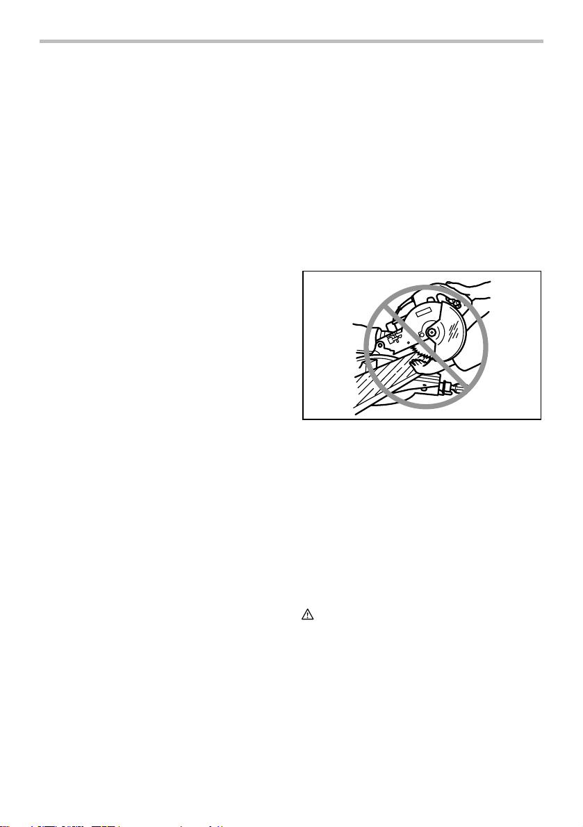
2. Keep hands out of path of saw blade. Avoid
contact with any coasting blade. It can still
cause severe injury.
3. Do not operate saw without guards in place.
Check blade guard for proper closing before
each use. Do not operate saw if blade guard
does not move freely and close instantly.
Never clamp or tie the blade guard into the
open position.
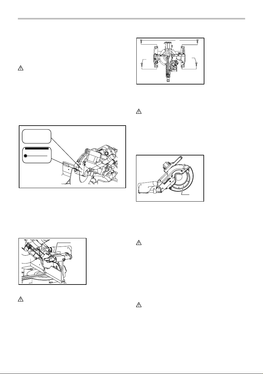
4. Do not perform any operation freehand. The
workpiece must be secured firmly against the
turn base and guide fence with a vise during
all operations. Never use your hand to secure
the workpiece.
5. Never reach around saw blade.
6. Turn off tool and wait for saw blade to stop
before moving workpiece or changing
settings.
7. Unplug tool before changing blade or
servicing.
8. To reduce the risk of injury, return carriage to
the full rear position after each crosscut
operation.
9. Always secure all moving portions before
carrying the tool.
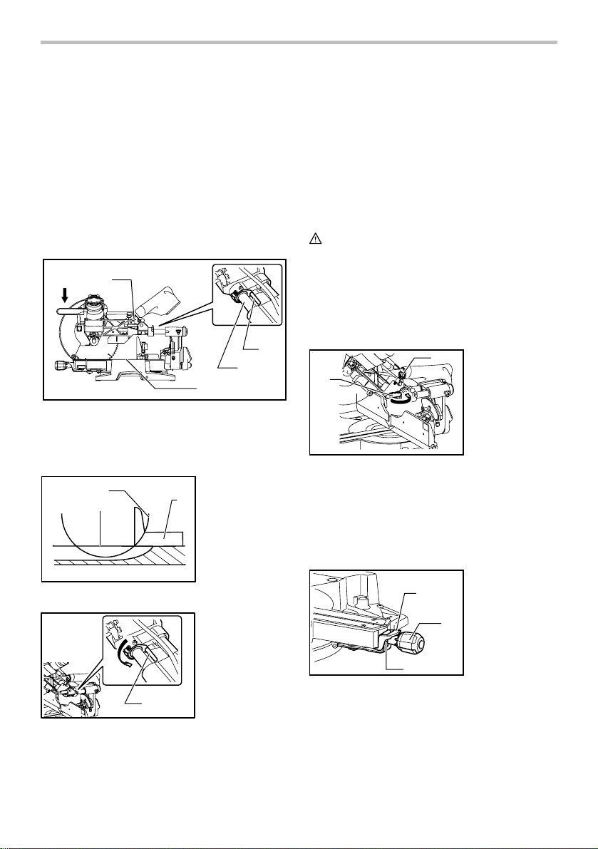
10. Stopper pin which locks the cutter head down
is for carrying and storage purposes only and
not for any cutting operations.

5
11. Do not use the tool in the presence of
flammable liquids or gases. The electrical
operation of the tool could create an explosion
and fire when exposed to flammable liquids or
gases.
12. Check the blade carefully for cracks or
damage before operation. Replace cracked or
damaged blade immediately. Gum and wood
pitch hardened on blades slows saw and
increases potential for kickback. Keep blade clean
by first removing it from tool, then cleaning it with
gum and pitch remover, hot water or kerosene.
Never use gasoline to clean blade.
13. While making a slide cut, KICKBACK can
occur. KICKBACK occurs when the blade
binds in the workpiece during a cutting
operation and the saw blade is driven rapidly
towards the operator. Loss of control and
serious personal injury can result. If blade
begins to bind during a cutting operation, do
not continue to cut and release switch
immediately.
14. Use only flanges specified for this tool.
15. Be careful not to damage the arbor, flanges
(especially the installing surface) or bolt.
Damage to these parts could result in blade
breakage.
16. Make sure that the turn base is properly
secured so it will not move during operation.
Use the holes in the base to fasten the saw to a
stable work platform or bench. NEVER use tool
where operator positioning would be
awkward.
17. For your safety, remove the chips, small
pieces, etc. from the table top before
operation.
18. Avoid cutting nails. Inspect for and remove all
nails from the workpiece before operation.
19. Make sure the shaft lock is released before the
switch is turned on.
20. Be sure that the blade does not contact the
turn base in the lowest position.
21. Hold the handle firmly. Be aware that the saw
moves up or down slightly during start-up and
stopping.
22. Make sure the blade is not contacting the
workpiece before the switch is turned on.
23. Before using the tool on an actual workpiece,
let it run for a while. Watch for vibration or
wobbling that could indicate poor installation
or a poorly balanced blade.
24. Wait until the blade attains full speed before
cutting.
25. Stop operation immediately if you notice
anything abnormal.
26. Do not attempt to lock the trigger in the "ON"
position.
27. Be alert at all times, especially during
repetitive, monotonous operations. Do not be
lulled into a false sense of security. Blades are
extremely unforgiving.
28. Always use accessories recommended in this
manual. Use of improper accessories such as
abrasive wheels may cause an injury.
29. NEVER hold workpiece on right side of blade
with left hand or vice versa. This is called
cross-armed cutting and exposes user to risk
of SERIOUS PERSONAL INJURY as shown in
the figure. ALWAYS use vise to secure
workpiece.
000030
30. Do not abuse cord. Never yank cord to
disconnect it from the receptacle. Keep cord
away from heat, oil, water and sharp objects.
31. NEVER stack workpieces on the table top to
speed cutting operations. Cut only one piece
at a time.
32. Some material contains chemicals which may
be toxic. Take caution to prevent dust
inhalation and skin contact. Follow material
supplier safety data.
SAVE THESE INSTRUCTIONS.
WARNING:
MISUSE or failure to follow the safety rules stated in
this instruction manual may cause serious personal
injury.

6
USB094-1
ADDITIONAL SAFETY RULES
FOR THE LASER
CAUTION:
• LASER RADIATION DO NOT STARE INTO
BEAM.
• AVOID EXPOSURE - LASER RADIATION IS
EMITTED FROM APERTURE.
• USE OF CONTROLS OR ADJUSTMENTS OR
PERFORMANCE OF PROCEDURES OTHER
THAN THOSE SPECIFIED HEREIN MAY
RESULT IN HAZARDOUS RADIATION
EXPOSURE.
Complies with 21CFR
1040.10 and 1040.11
AVOID EXPOSURE-Laser
radiation is emitted from
LASER RADIATION
this aperture
DO NOT STARE INTO BEAM
Maximum Output
<1mW,Wavelength:655nm
CLASS II LASER PRODUCT
CAUTION
009605
INSTALLATION
Bench mounting
When the tool is shipped, the handle is locked in the
lowered position by the stopper pin. Release the stopper
pin by simultaneously applying a slight downward
pressure on the handle and pulling the stopper pin.
1
009483
WARNING:
• Ensure that the tool will not move on the
supporting surface. Movement of the miter saw
on the supporting surface while cutting may result
in loss of control and serious personal injury.
This tool should be bolted with four bolts to a level and
stable surface using the bolt holes provided in the tool's
base. This will help prevent tipping and possible injury.
1
11
010593
FUNCTIONAL DESCRIPTION
WARNING:
• Always be sure that the tool is switched off and
unplugged before adjusting or checking
function on the tool. Failure to switch off and
unplug the tool may result in serious personal
injury from accidental start-up.
Blade guard
1
009485
When lowering the handle, the blade guard rises
automatically. The blade guard returns to its original
position when the cut is completed and the handle is
raised.
WARNING:
• Never defeat or remove the blade guard or the
spring which attaches to the guard. An exposed
blade as a result of defeated guarding may result
in serious personal injury during operation.
In the interest of your personal safety, always maintain
the blade guard in good condition. Any irregular
operation of the blade guard should be corrected
immediately. Check to assure spring loaded return
action of guard.
WARNING:
• Never use the tool if the blade guard or spring
are damaged, faulty or removed. Operation of
the tool with a damaged, faulty or removed guard
may result in serious personal injury.
If the see-through blade guard becomes dirty, or
sawdust adheres to it in such a way that the blade
1. Blade guard
1. Hex bolts
1. Stopper pin

7
and/or workpiece is no longer easily visible, unplug the
saw and clean the guard carefully with a damp cloth. Do
not use solvents or any petroleum-based cleaners on
the plastic guard because this may cause damage to the
guard.
If the blade guard becomes dirty and needs to be
cleaned for proper operation follow the steps below:
With the tool switched off and unplugged, use the
supplied socket wrench to loosen the hex bolt holding
the center cover. Loosen the hex bolt by turning it
counterclockwise and raise the blade guard and center
cover. With the blade guard so positioned, cleaning can
be more completely and efficiently accomplished. When
cleaning is complete reverse procedure above and
secure bolt. Do not remove spring holding blade guard.
If guard becomes damaged through age or UV light
exposure, contact a Makita service center for a new
guard. DO NOT DEFEAT OR REMOVE GUARD.
1
009486
Positioning kerf board
1
009488
1
2
3
4
5
6
001538
This tool is provided with the kerf boards in the turn base
to minimize tearing on the exit side of a cut. The kerf
boards are factory adjusted so that the saw blade does
not contact the kerf boards. Before use, adjust the kerf
boards as follows:
1
2
009496
First, unplug the tool. Loosen all the screws (3 each on
left and right) securing the kerf boards. Re-tighten them
only to the extent that the kerf boards can still be easily
moved by hand. Lower the handle fully and push in the
stopper pin to lock the handle in the lowered position.
Loosen the locking screw counterclockwise which
secures the upper slide poles and also push forward the
lock lever which secures the lower slide poles. Pull the
carriage toward you fully. Adjust the kerf boards so that
the kerf boards just contact the sides of the blade teeth.
Tighten the front screws (do not tighten firmly). Push the
carriage toward the guide fence fully and adjust the kerf
boards so that the kerf boards just contact the sides of
blade teeth. Tighten the rear screws (do not tighten
firmly).
After adjusting the kerf boards, release the stopper pin
and raise the handle. Then tighten all the screws
securely.
1. Lock lever
2. Locking screw
1. Saw blade
2. Blade teeth
3. Kerf board
4. Left bevel cut
5. Straight cut
6. Right bevel cut
1. Kerf board
1. Blade guard

8
NOTICE:
• After setting the bevel angle ensure that the
kerf boards are adjusted properly. Correct
adjustment of the kerf boards will help provide
proper support of the workpiece minimizing
workpiece tear out.
Maintaining maximum cutting capacity
This tool is factory adjusted to provide the maximum
cutting capacity for a 305mm (12") saw blade.
Unplug the tool before any adjustment is attempted.
When installing a new blade, always check the lower
limit position of the blade and if necessary, adjust it as
follows:
1
2
3
4
009518
2
13
009737
1
009736
First, unplug the tool. Lower the stopper lever to position
the saw blade as shown in the figure. Push the carriage
toward the guide fence fully and lower the handle
completely. Use the socket wrench to turn the adjusting
bolt until the periphery of the blade extends slightly
below the top surface of the turn base at the point where
the front face of the guide fence meets the top surface of
the turn base.
With the tool unplugged, rotate the blade by hand while
holding the handle all the way down to be sure that the
blade does not contact any part of the lower base.
Re-adjust slightly, if necessary.
After adjustment, always return the stopper lever to the
original position by turning it counterclockwise.
WARNING:
• After installing a new blade and with the tool
unplugged, always be sure that the blade does
not contact any part of the lower base when the
handle is lowered completely. If a blade makes
contact with the base it may cause kickback and
result in serious personal injury.
Stopper arm
1
2
009487
The lower limit position of the blade can be easily
adjusted with the stopper arm. To adjust it, rotate the
stopper arm in the direction of the arrow as shown in the
figure. Adjust the adjusting screw so that the blade stops
at the desired position when lowering the handle fully.
Adjusting the miter angle
1
2
3
009517
Push the grip so that the cams engages and turn it
clockwise until it stops. Turn the turn base while pressing
down the lock lever. When you have moved the grip to
the position where the pointer points to the desired angle
on the miter scale, turn the grip 90° counterclockwise to
lock the turn base.
1. Lock lever
2. Grip
3. Cam
1. Stopper arm
2. Adjusting screw
1. Stopper lever
1. Top surface of
turn base
2. Periphery of
blade
3. Guide fence
1. Adjusting bolt
2. Turn base
3. Stopper lever
4. Slide pipe

9
CAUTION:
• After changing the miter angle, always secure the
turn base by turning the grip 90° counterclockwise.
NOTICE:
• When turning the turn base, be sure to raise the
handle fully.
Adjusting the bevel angle
To adjust the bevel angle, loosen the lever at the rear of
the tool counterclockwise. Push the latch lever forward
as shown in the figure fully while supporting the weight
of the saw head so as to release the pressure on the
lock pin.
When tilting the carriage to the right, tilt the carriage to
the left slightly after loosening the lever and press the
releasing button. With the releasing button being
pressed, tilt the carriage to the right.
1
009489
1
010322
Tilt the saw blade until the pointer points to the desired
angle on the bevel scale. Then tighten the lever
clockwise firmly to secure the arm.
1
2
4
3
009513
When the latch lever is pulled towards the front of the
saw, the saw blade can be locked using positive stops
at the right and left 22.5 ° and 33.9 ° angle to the base
surface.
When the latch lever is pushed to the back of the saw as
shown in the figure, the saw blade can be locked at any
desired angle within the specified bevel angle range.
CAUTION:
• After changing the bevel angle, always secure the
arm by tightening the lever clockwise.
NOTICE:
• When tilting the saw blade be sure the handle is
fully raised.
• When changing bevel angles, be sure to position
the kerf boards appropriately as explained in the
"Positioning kerf boards" section.
Slide lock adjustment
1
2
009496
To lock the lower slide pole, pull the lock lever towards
the front of the saw.
To lock the upper slide pole, turn the locking screw
clockwise.
Switch action
To prevent the switch trigger from being accidentally
pulled, a lock-off button is provided. To start the tool,
press in the lock-off button and pull the switch trigger.
Release the switch trigger to stop.
WARNING:
• Before plugging in the tool, always check to
see that the switch trigger actuates properly
and returns to the "OFF" position when
released. Do not pull the switch trigger hard
without pressing in the lock-off button. This
can cause switch breakage. Operating a tool with
a switch that does not actuate properly can lead to
loss of control and serious personal injury.
A hole is provided in the switch trigger for insertion of a
padlock to lock the tool off.
1. Lock lever
2. Locking screw
1. Scale plate
2. Release button
3. Pointer
4. Latch lever
1. Latch lever
1. Lever

10
1
2
3
009491
WARNING:
• Do not use a lock with a shank or cable any
smaller than 6.35 mm (1/4") in diameter. A
smaller shank or cable may not properly lock the
tool in the off position and unintentional operation
may occur resulting in serious personal injury.
• NEVER use tool without a fully operative switch
trigger. Any tool with an inoperative switch is
HIGHLY DANGEROUS and must be repaired
before further usage or serious personal injury may
occur.
• For your safety, this tool is equipped with a lock-off
button which prevents the tool from unintended
starting. NEVER use the tool if it runs when you
simply pull the switch trigger without pressing the
lock-off button. A switch in need of repair may
result in unintentional operation and serious
personal injury. Return tool to a Makita service
center for proper repairs BEFORE further usage.
• NEVER defeat the lock-off button by taping down
or some other means. A switch with a defeated
lock-off button may result in unintentional operation
and serious personal injury.
Electric brake
This tool is equipped with an electric blade brake. If the
tool consistently fails to quickly stop the blade after the
switch trigger is released, have the tool serviced at a
Makita service center.
CAUTION:
• The blade brake system is not a substitute for
the blade guard. Never use tool without a
functioning blade guard. An unguarded blade
may result in serious personal injury.
Electronic function
Constant speed control
• The tool is provided with an electronic speed
control which helps maintain a constant blade
rotation speed even under load. A constant blade
rotation speed will result in a very smooth cut.
Soft start feature
• This function allows the smooth start-up of the tool
by limiting the start-up torque.
Laser beam action
For model LS1216L only
1
009492
CAUTION:
• LASER RADIATION
Do not stare into beam.
To turn on the laser beam, press the upper position (I) of
the switch. To turn off the laser beam, press the lower
position (0) of the switch.
Laser line can be shifted to either the left or right side of
the saw blade by adjusting the adjusting screw as
follows.
1
009493
1. Loosen the adjusting screw by turning it
counterclockwise.
2. With the adjusting screw loosened, slide the
adjusting screw to the right or left as far as it goes.
3. Tighten the adjusting screw firmly at the position
where it stops sliding.
Laser line is factory adjusted so that it is positioned
within 1 mm (0.04") from the side surface of the blade
(cutting position).
NOTE:
• When laser line appears dim and hard to see
because of direct sunlight, relocate the work area
to a place where there is less direct sunlight.
1. Adjusting screw
1. Switch for laser
1. Switch trigger
2. Lock-off button
3. Hole for padlock

11
Aligning the laser line
AB
009494
Laser line can be shifted to either the left or right side of
the blade according to the applications of cutting. Refer
to explanation titled "Laser beam action" regarding its
shifting method.
NOTE:
• Use wood facing against the guide fence when
aligning the cutting line with the laser line at the
side of guide fence in compound cutting (bevel
angle 45 degrees and miter angle right 45
degrees).
A) When you obtain the correct size on the left side of
workpiece
• Shift the laser line to the left of the blade.
B) When you obtain the correct size on the right side of
workpiece
• Shift the laser line to the right of the blade.
Align the cutting line on your workpiece with the laser
line.
ASSEMBLY
WARNING:
• Always be sure that the tool is switched off and
unplugged before working on the tool. Failure to
switch off and unplug the tool may result in serious
personal injury.
Socket wrench storage
1
2
009495
The socket wrench is stored as shown in the figure.
When the socket wrench is needed it can be pulled out
of the wrench holder.
After using the socket wrench it can be stored by
returning it to the wrench holder.
Installing or removing saw blade
WARNING:
• Always be sure that the tool is switched off and
unplugged before installing or removing the
blade. Accidental start up of the tool may result in
serious personal injury.
• Use only the Makita socket wrench provided to
install or remove the blade.Failure to use the
wrench may result in overtightening or insufficient
tightening of the hex bolt and serious personal
injury.
Lock the handle in the raised position by pushing in the
stopper pin.
1
009483
To remove the blade, use the socket wrench to loosen
the hex bolt holding the center cover by turning it
counterclockwise. Raise the blade guard and center
cover.
1
23
4
009497
Press the shaft lock to lock the spindle and use the
socket wrench to loosen the hex bolt clockwise. Then
remove the hex bolt, outer flange and blade.
1. Center cover
2. Socket wrench
3. Hex bolt
4. Blade guard
1. Stopper pin
1. Wrench holder
2. Socket wrench

12
1
2
3
009498
NOTE:
• If the inner flange is removed be sure to install it on
the spindle with its protrusion facing away from the
blade. If the flange is installed incorrectly the
flange will rub against the machine.
WARNING:
• Before mounting the blade onto the spindle,
always be sure that the correct ring for the
blade's arbor hole you intend to use is installed
between the inner and the outer flanges. Use of
the incorrect arbor hole ring may result in the
improper mounting of the blade causing blade
movement and severe vibration resulting in
possible loss of control during operation and in
serious personal injury.
To install the blade, mount it carefully onto the spindle,
making sure that the direction of the arrow on the
surface of the blade matches the direction of the arrow
on the blade case.
Install the outer flange and hex bolt, and then use the
socket wrench to tighten the hex bolt (left-handed)
securely counterclockwise while pressing the shaft lock.
12
34
009500
123
45
6
009925
Return the blade guard and center cover to its original
position. Then tighten the hex bolt clockwise to secure
the center cover. Release the handle from the raised
position by pulling the stopper pin. Lower the handle to
make sure that the blade guard moves properly. Make
sure the shaft lock has released spindle before making
cut.
1
009524
Dust bag
1
23
009501
The use of the dust bag makes cutting operations
cleaner and dust collection easier. To attach the dust
bag, fit it onto the dust nozzle.
When the dust bag is about half full, remove the dust
bag from the tool and pull the fastener out. Empty the
dust bag of its contents, tapping it lightly so as to remove
particles adhering to the insides which might hamper
further collection.
NOTE:
If you connect a vacuum cleaner to your saw, cleaner
operations can be performed.
1. Fastener
2. Dust bag
3. Dust nozzle
1. Hex bolt
1. Hex bolt
2. Outer flange
3. Saw blade
4. Inner flange
5. Spindle
6. Ring
1. Arrow
2. Arrow
3. Blade case
4. Saw blade
1. Shaft lock
2. Blade case
3. Hex bolt

13
Dust box (Optional accessory)
1
2
3
006793
Insert the dust box into the dust nozzle.
Empty the dust box when necessary.
To empty the dust box, open the cover by pushing the
button and dispose of the sawdust. Return the cover to
the original position and lock it in place. Dust box can
easily be removed by pulling it out while turning it near
the dust nozzle on the tool.
NOTE:
• If you connect a Makita vacuum cleaner to this tool,
cleaner operations can be performed.
NOTICE:
• Empty the dust box before collected sawdust level
reaches the cylinder section.
1
23
010592
1
2
010591
Securing workpiece
WARNING:
• It is extremely important to always secure the
workpiece correctly with the proper type of vise
or crown molding stoppers. Failure to do so may
result in serious personal injury and cause damage
to the tool and/or the workpiece.
• After a cutting operation do not raise the blade
until it has come to a complete stop. The raising
of a coasting blade may result in serious personal
injury and damage to the workpiece.
• When cutting a workpiece that is longer than
the support base of the saw, the material
should be supported the entire length beyond
the support base and at the same height to
keep the material level. Proper workpiece support
will help avoid blade pinch and possible kickback
which may result in serious personal injury. Do not
rely solely on the vertical vise and/or horizontal
vise to secure the workpiece. Thin material tends
to sag. Support workpiece over its entire length to
avoid blade pinch and possible KICKBACK.
12
001549
Guide fence (SLIDING FENCES which are
upper and lower fences) adjustment
WARNING:
• Before operating the tool, make sure that the upper
and lower fences are secured firmly.
• Before bevel-cutting, make sure that no part of
the tool, especially the blade, contacts the
upper and lower fences when fully lowering
and raising the handle in any position and while
moving the carriage through its full range of
travel. If the tool or blade makes contact with the
fence this may result in kickback or unexpected
movement of the material and serious personal
injury.
1
2
009508
The lower fences can be moved inward and outward by
loosening the clamping screws.
1. Levers
2. Clamping
screws
1. Support
2. Turn base
1. Cylinder section
2. Dust box
1. Cylinder section
2. Dust box
3. Sawdust
1. Dust box
2. Cover
3. Button

14
12
3
010594
A red indicating area will appear as the lower fences are
moved inward and will disappear as the lower fences are
moved outward.
The upper fences can be removed or moved inward and
outward by loosening the levers.
009611
In case of bevel-cutting, adjust the lower and upper
fence positions to be as close to the blade as practical to
provide maximum workpiece support, and make sure
that no part of the tool, especially the blade, contacts the
lower and upper fences when lowering and raising the
handle fully at any position and pulling or pushing the
carriage all the way at the lowest position.
Before cutting operations, make a dry run with the saw
turned off and unplugged, then check clearance
between fences and moving parts.
Before cutting operations, firmly secure lower fences by
tightening the clamping screws and upper fences by
tightening the levers.
When bevel-cutting operations are complete, don’t
forget to return the upper fences to the original position
and return it.
Vertical vise
1
2
3
4
009502
The vertical vise can be installed in two positions on
either the left or right side of the base. Insert the vise rod
into the hole in the base.
Position the vise arm according to the thickness and
shape of the workpiece and secure the vise arm by
tightening the screw. If the screw to secure the vise arm
contacts the carriage, install the screw on the opposite
side of vise arm. Make sure that no part of the tool
contacts the vise when lowering the handle fully and
pulling or pushing the carriage all the way. If some part
contacts the vise, re-position the vise.
Press the workpiece flat against the guide fence and the
turn base. Position the workpiece at the desired cutting
position and secure it firmly by tightening the vise knob.
Turning the vise knob to 90° counterclockwise allows the
vise knob to be moved up and down, facilitating the
quick setting of workpiece. To secure the workpiece after
setting, turn the vise knob clockwise.
WARNING:
• The workpiece must be secured firmly against
the turn base and guide fence with the vise
during all operations. If the workpiece is not
properly secured against the fence the material
may move during the cutting operation causing
possible damage to the blade, causing the material
to be thrown and loss of control resulting in serious
personal injury.
Horizontal vise (optional accessory)
12
3
009606
The horizontal vise can be installed in two positions on
either the left or right side of the base. When performing
15° or greater miter cuts, install the horizontal vise on
the side opposite the direction in which the turn base is
to be turned.
005232
1. Vise plate
2. Vise nut
3. Vise knob
1. Vise knob
2. Vise arm
3. Vise rod
4. Screw
1. Upper fence
2. Lower fence
3. Red indicating
area

15
By flipping the vise nut counterclockwise, the vise is
released, and rapidly moves in and out. To grip the
workpiece, push the vise knob forward until the vise
plate contacts the workpiece and flip the vise nut
clockwise. Then turn the vise knob clockwise to secure
the workpiece.
The maximum width of workpiece which can be secured
by the horizontal vise is 215 mm (8-1/2").
WARNING:
• Always rotate the vise nut clockwise until the
workpiece is properly secured. If the workpiece
is not properly secured the material may move
during the cutting operation causing possible
damage to the blade, causing the material to be
thrown and loss of control resulting in serious
personal injury.
• When cutting a thin workpiece, such as base
boards, against the fence, always use the
horizontal vise.
Holders (Optional accessory)
12
009607
The holders can be installed on either side as a
convenient means of holding workpieces horizontally.
Slip the holder rods into the holes in the base and adjust
their length according to the workpiece to be held. Then
tighten the holders securely with the screws.
WARNING:
• Always support a long workpiece so it is level
with the top surface of the turn base for an
accurate cut and to prevent dangerous loss of
tool control. Proper workpiece support will help
avoid blade pinch and possible kickback which
may result in serious personal injury.
OPERATION
NOTICE:
• Before use, be sure to release the handle from the
lowered position by pulling the stopper pin.
• Do not apply excessive pressure on the handle
when cutting. Too much force may result in
overload of the motor and/or decreased cutting
efficiency. Push down handle with only as much
force as is necessary for smooth cutting and
without significant decrease in blade speed.
• Gently press down the handle to perform the cut. If
the handle is pressed down with force or if lateral
force is applied, the blade will vibrate and leave a
mark (saw mark) in the workpiece and the
precision of the cut will be impaired.
• During a slide cut, gently push the carriage toward
the guide fence without stopping. If the carriage
movement is stopped during the cut, a mark will be
left in the workpiece and the precision of the cut
will be impaired.
WARNING:
• Make sure the blade is not contacting the
workpiece, etc. before the switch is turned on.
Turning the tool on with the blade in contact with
the workpiece may result in kickback and serious
personal injury.
1. Press cutting (cutting small workpieces)
009503
Workpieces up to 92 mm (3-5/8") high and 183 mm
(7-1/4") wide can be cut in the following manner.
After turning the stopper lever clockwise and sliding the
carriage to your desired position, push the carriage
toward the guide fence fully and tighten the locking screw
clockwise and pull the lock lever towards the front of the
saw to secure the carriage. Secure the workpiece
correctly with the proper type of vise or crown molding
stoppers. Switch on the tool without the blade making
any contact and wait until the blade attains full speed
before lowering. Then gently lower the handle to the fully
lowered position to cut the workpiece. When the cut is
completed, switch off the tool and WAIT UNTIL THE
BLADE HAS COME TO A COMPLETE STOP before
returning the blade to its fully elevated position.
WARNING:
• Firmly tighten the locking screw clockwise and
pull the lock lever towards the front of the saw
so that the carriage will not move during
operation. Insufficient tightening of the locking
screw may cause possible kickback which may
result in serious personal injury.
1. Holder
2. Screw

16
2. Slide (push) cutting (cutting wide workpieces)
1
2
009496
Loosen the locking screw counterclockwise and
also push forward the lock lever so that the
carriage can slide freely. Secure the workpiece
with the proper type of vise.
009504
Pull the carriage toward you fully. Switch on the
tool without the blade making any contact and wait
until the blade attains full speed. Press the handle
down and PUSH THE CARRIAGE TOWARD THE
GUIDE FENCE AND THROUGH THE
WORKPIECE. When the cut is completed, switch
off the tool and WAIT UNTIL THE BLADE HAS
COME TO A COMPLETE STOP before returning
the blade to its fully elevated position.
WARNING:
• Whenever performing a slide cut, first pull the
carriage full towards you and press the handle
all the way down, then push the carriage toward
the guide fence. Never start the cut with the
carriage not pulled fully toward you. If you
perform the slide cut without the carriage pulled
fully toward you unexpected kickback may occur
and serious personal injury may result.
• Never attempt to perform a slide cut by pulling
the carriage towards you. Pulling the carriage
towards you while cutting may cause unexpected
kickback resulting in possible serious personal
injury.
• Never perform the slide cut with the handle locked
in the lowered position.
• Never loosen the knob which secures the
carriage while the blade is rotating. A loose
carriage while cutting may cause unexpected
kickback resulting in possible in serious personal
injury.
3. Miter cutting
Refer to the previously covered "Adjusting the
miter angle".
4. Bevel cut
009505
Loosen the lever and tilt the saw blade to set the
bevel angle (Refer to the previously covered
"Adjusting the bevel angle"). Be sure to retighten
the lever firmly to secure the selected bevel angle
safely. Secure the workpiece with a vise. Make
sure the carriage is pulled all the way back toward
the operator. Switch on the tool without the blade
making any contact and wait until the blade attains
full speed. Then gently lower the handle to the fully
lowered position while applying pressure in parallel
with the blade and PUSH THE CARRIAGE
TOWARD THE GUIDE FENCE TO CUT THE
WORKPIECE. When the cut is completed, switch
off the tool and WAIT UNTIL THE BLADE HAS
COME TO A COMPLETE STOP before returning
the blade to its fully elevated position.
WARNING:
• After setting the blade for a bevel cut, before
operating the tool ensure that the carriage and
blade will have free travel throughout the entire
range of the intended cut. Interruption of the
carriage or blade travel during the cutting operation
may result in kickback and serious personal injury.
• While making a bevel cut keep hands out of the
path of the blade. The angle of the blade may
confuse the operator as to the actual blade path
while cutting and contact with the blade will result
in serious personal injury.
• The blade should not be raised until it has
come to a complete stop. During a bevel cut the
piece cut off may come to rest against the blade.
If the blade is raised while it is rotating the cut-off
piece maybe ejected by the blade causing the
material to fragment which may result in serious
personal injury.
1. Lock lever
2. Locking screw

17
NOTICE:
• When pressing down the handle, apply pressure in
parallel with the blade. If a force is applied
perpendicularly to the turn base or if the pressure
direction is changed during a cut, the precision of
the cut will be impaired.
• Before bevel-cutting, an adjustment of the upper
fence and lower fence maybe required. Refer to
the section titled "Guide fence adjustment".
5. Compound cutting
Compound cutting is the process in which a bevel
angle is made at the same time in which a miter
angle is being cut on a workpiece. Compound
cutting can be performed at the angle shown in the
table.
Miter angle Bevel angle
Left and Right 0 - 45
009713
When performing compound cutting, refer to
"Press cutting", "Slide cutting", "Miter cutting" and
"Bevel cut" explanations.
6. Cutting crown and cove moldings
Crown and cove moldings can be cut on a
compound miter saw with the moldings laid flat on
the turn base.
There are two common types of crown moldings
and one type of cove moldings; 52/38° wall angle
crown molding, 45° wall angle crown molding and
45° wall angle cove molding. See illustrations.
52
38
45
45
45
45
123
001555
There are crown and cove molding joints which are
made to fit "Inside" 90° corners ((1) and (2) in Fig.
A) and "Outside" 90° corners ((3) and (4) in Fig. A).
(1) (2) (3) (4)
1 2
Fig.A
001556
2
(1)
(2)
(1)
(2)
(2)
(1)
(2)
(1)
(1)
(2)
(3)
(4)
1
001557
Measuring
Measure the wall length and adjust workpiece on
table to cut wall contact edge to desired length.
Always make sure that cut workpiece length at the
back of the workpiece is the same as wall length.
Adjust cut length for angle of cut. Always use
several pieces for test cuts to check the saw
angles.
When cutting crown and cove moldings, set the
bevel angle and miter angle as indicated in the
table (A) and position the moldings on the top
surface of the saw base as indicated in the table
(B).
In the case of left bevel cut
Molding
position in
Fig. A
Bevel angleMiter angle
For outside
corner
For inside
corner
52/38° type 45° type
Right 31.6°
45° type
Left 33.9° Left 30°
52/38° type
Left 31.6°Left 35.3°
Right 35.3°
Right 35.3°Right 31.6°
(1)
(2)
(3)
(4)
Table(A)
006361
Molding
position in
Fig. A
Molding edge against
guide fence
(1)Ceiling contactedge should
beagainst guide fence.
Ceiling contactedge should
beagainst guide fence.
For
outside
corner
Finished piece
will beon the
Left side of
blade.
Finished piece
will beon the
Right side of
blade.
For inside
corner
Wall contactedge shouldbe
against guide fence.
Finished piece
(2)
(3)
(4)
Table(B)
006362
Example:
In the case of cutting 52/38° type crown
molding for position (1) in Fig. A:
• Tilt and secure bevel angle setting to
33.9° LEFT.
• Adjust and secure miter angle setting to
31.6° RIGHT.
1. Inside corner
2. Outside corner
1. Inside corner
2. Outside corner
1. 52/38 ゚type
crown molding
2. 45 ゚type crown
molding
3. 45 ゚type cove
molding

18
• Lay crown molding with its broad back
(hidden) surface down on the turn base
with its CEILING CONTACT EDGE
against the guide fence on the saw.
• The finished piece to be used will
always be on the LEFT side of the blade
after the cut has been made.
In the case of right bevel cut
Molding
position in
Fig. A
Bevel angleMiter angle
For outside
corner
For inside
corner
52/38° type 45° type
Right 31.6°
45° type
Right 33.9° Right 30°
52/38° type
Left 31.6°Left 35.3°
Right 35.3°
Right 35.3°Right 31.6°
(1)
(2)
(3)
(4)
Table(A)
006363
Molding
position in
Fig. A
Molding edge against
guide fence
(1)
For
outside
corner
For inside
corner
Finished piece
(2)
(3)
(4)
Table(B)
Finished piece
will beon the
Left side of
blade.
Finished piece
will beon the
Right side of
blade.
Wall contactedge shouldbe
against guide fence.
Wall contactedge shouldbe
against guide fence.
Ceiling contactedge should
beagainst guide fence.
006364
Example:
In the case of cutting 52/38° type crown
molding for position (1) in Fig. A:
• Tilt and secure bevel angle setting to
33.9° RIGHT.
• Adjust and secure miter angle setting to
31.6° RIGHT.
• Lay crown molding with its broad back
(hidden) surface down on the turn base
with its WALL CONTACT EDGE against
the guide fence on the saw.
• The finished piece to be used will
always be on the RIGHT side of the
blade after the cut has been made.

19
52°
38°
Ceiling
Wall
30.1
29.7
29.4
29.0
28.7
28.3
28.0
27.6
27.2
26.9
26.5
26.1
25.8
25.4
25.0
24.7
24.3
23.9
23.6
23.2
22.8
22.5
22.1
21.7
21.3
21.0
20.6
20.2
19.8
19.5
19.1
18.7
18.3
17.9
17.6
17.2
16.8
16.4
16.0
15.6
26.9
26.5
26.1
25.7
25.3
24.9
24.5
24.1
23.7
23.3
22.9
22.6
22.2
21.8
21.4
21.0
20.7
20.3
19.9
19.6
19.2
18.8
18.5
18.1
17.8
17.4
17.1
16.7
16.4
16.0
15.7
15.3
15.0
14.6
14.3
14.0
13.6
13.3
13.0
12.8
101
102
103
104
105
106
107
108
109
110
111
112
113
114
115
116
117
118
119
120
121
122
123
124
125
126
127
128
129
130
131
132
133
134
135
136
137
138
139
140
15.3
14.9
14.5
14.1
13.7
13.3
12.9
12.5
12.2
11.8
11.4
11.0
10.8
10.2
9.8
9.4
9.0
8.6
8.3
7.9
7.5
7.1
6.7
6.3
5.9
5.5
5.1
4.7
4.3
3.9
3.5
3.2
2.8
2.4
2.0
1.6
1.2
0.8
0.4
0.0
12.3
12.0
11.6
11.3
11.0
10.7
10.3
10.0
9.7
9.4
9.0
8.7
8.4
8.1
7.8
7.5
7.1
6.8
6.5
6.2
5.9
5.6
5.3
4.9
4.6
4.3
4.0
3.7
3.4
3.1
2.8
2.5
2.2
1.8
1.5
1.2
0.9
0.6
0.3
0.0
141
142
143
144
145
146
147
148
149
150
151
152
153
154
155
156
157
158
159
160
161
162
163
164
165
166
167
168
169
170
171
172
173
174
175
176
177
178
179
180
Wall to Crown Molding Angle: 52/38 degrees
Compound Miter Saw
Miter and Bevel Angle Settings
000031
Wall Angle
(deg.)
Bevel Angle
(deg.)
Miter Angle
(deg.)
Wall Angle
(deg.)
Bevel Angle
(deg.)
Miter Angle
(deg.)
43.0
42.8
42.5
42.2
41.9
41.7
41.4
41.1
40.8
40.5
40.2
39.9
39.6
39.3
39.0
38.7
38.4
38.1
37.8
37.4
37.1
36.8
36.5
36.2
35.8
35.5
35.2
34.9
34.5
34.2
33.9
33.5
33.2
32.8
32.5
32.2
31.8
31.5
31.1
30.8
30.4
46.8
46.3
45.7
45.1
44.6
44.0
43.5
42.9
42.4
41.9
41.3
40.8
40.3
39.8
39.2
38.7
38.2
37.7
37.2
36.8
36.3
35.8
35.3
34.8
34.4
33.9
33.4
33.0
32.5
32.1
31.6
31.2
30.7
30.3
29.9
29.4
29.0
28.6
28.2
27.7
27.3
60
61
62
63
64
65
66
67
68
69
70
71
72
73
74
75
76
77
78
79
80
81
82
83
84
85
86
87
88
89
90
91
92
93
94
95
96
97
98
99
100
Wall Angle
(deg.)
Bevel Angle
(deg.)
Miter Angle
(deg.)
EN0002-1

20
26.7
26.4
26.1
25.8
25.5
25.2
24.9
24.6
24.2
23.9
23.6
23.3
23.0
22.7
22.3
22.0
21.7
21.4
21.0
20.7
20.4
20.0
19.7
19.4
19.1
18.7
18.4
18.1
17.7
17.4
17.1
16.7
16.4
16.0
15.7
15.4
15.0
14.7
14.3
14.0
30.2
29.8
29.4
28.9
28.5
28.1
27.6
27.2
26.8
26.3
25.9
25.5
25.1
24.7
24.3
23.8
23.4
23.0
22.6
22.2
21.8
21.4
21.0
20.6
20.2
19.8
19.4
19.0
18.6
18.2
17.9
17.5
17.1
16.7
16.3
15.9
15.6
15.2
14.8
14.4
101
102
103
104
105
106
107
108
109
110
111
112
113
114
115
116
117
118
119
120
121
122
123
124
125
126
127
128
129
130
131
132
133
134
135
136
137
138
139
140
13.7
13.3
13.0
12.6
12.3
11.9
11.6
11.2
10.9
10.5
10.2
9.8
9.5
9.2
8.8
8.5
8.1
7.8
7.4
7.1
6.7
6.4
6.0
5.6
5.3
4.9
4.6
4.2
3.9
3.5
3.2
2.8
2.5
2.1
1.8
1.4
1.1
0.7
0.4
0.0
14.1
13.7
13.3
12.9
12.6
12.2
11.8
11.5
11.1
10.7
10.4
10.0
9.6
9.3
8.9
8.5
8.2
7.8
7.5
7.1
6.7
6.4
6.0
5.7
5.3
5.0
4.6
4.3
3.9
3.5
3.2
2.8
2.5
2.1
1.8
1.4
1.1
0.7
0.4
0.0
141
142
143
144
145
146
147
148
149
150
151
152
153
154
155
156
157
158
159
160
161
162
163
164
165
166
167
168
169
170
171
172
173
174
175
176
177
178
179
180
Wall to Crown Molding Angle: 45 degrees
Compound Miter Saw
Miter and Bevel Angle Settings
000032
Wall Angle
(deg.)
Bevel Angle
(deg.)
Miter Angle
(deg.)
Wall Angle
(deg.)
Bevel Angle
(deg.)
Miter Angle
(deg.)
37.8
37.5
37.3
37.1
36.8
36.6
36.4
36.1
35.9
35.6
35.4
35.1
34.9
34.6
34.4
34.1
33.9
33.6
33.3
33.1
32.8
32.5
32.3
32.0
31.7
31.4
31.1
30.9
30.6
30.3
30.0
29.7
29.4
29.1
28.8
28.5
28.2
27.9
27.6
27.3
27.0
50.8
50.2
49.6
49.1
48.5
48.0
47.4
46.9
46.4
45.8
45.3
44.8
44.2
43.7
43.2
42.7
42.1
41.6
41.1
40.6
40.1
39.6
39.1
38.6
38.1
37.7
37.2
36.7
36.2
35.7
35.3
34.8
34.3
33.9
33.4
32.9
32.5
32.0
31.6
31.1
30.7
60
61
62
63
64
65
66
67
68
69
70
71
72
73
74
75
76
77
78
79
80
81
82
83
84
85
86
87
88
89
90
91
92
93
94
95
96
97
98
99
100
Wall Angle
(deg.)
Bevel Angle
(deg.)
Miter Angle
(deg.)
45°
45°
Ceiling
Wall
EN0003-1
Crown molding stoppers (optional accessories)
allow easier cuts of crown molding without tilting
the saw blade. Install them on the base as shown
in the figures.
Other manuals for LS1216
10
This manual suits for next models
1
Table of contents
Languages:
Other Makita Saw manuals

Makita
Makita LS1214 User manual

Makita
Makita LH1201FL User manual

Makita
Makita 5044KB User manual

Makita
Makita LS1013 User manual

Makita
Makita 5007N User manual

Makita
Makita JR1000FT User manual

Makita
Makita JR002GZ User manual

Makita
Makita DUC101 User manual

Makita
Makita 5104S User manual

Makita
Makita 2705 User manual

Makita
Makita DJR189 User manual

Makita
Makita XBP01T User manual

Makita
Makita JR180DWB User manual

Makita
Makita JR3051TK User manual

Makita
Makita 5007MG User manual

Makita
Makita 2705 User manual

Makita
Makita DLS714 User manual

Makita
Makita DPB181 User manual

Makita
Makita DLS110 User manual

Makita
Makita 5377MG Quick start guide