Makita M2300 User manual

INSTRUCTION MANUAL
MANUEL D'INSTRUCTION
MANUAL DE INSTRUCCIONES
Compound Miter Saw
Scie à Coupe d’Onglet
Sierra De Inglete Mixta
M2300
IMPORTANT: Read Before Using.
IMPORTANT : Lire avant usage.
IMPORTANTE: Lea antes de usar.
DOUBLE INSULATION
DOUBLE ISOLATION
DOBLE AISLAMIENTO

2ENGLISH
ENGLISH (Original instructions)
SPECIFICATIONS
Model: M2300
Blade diameter 255 mm (10")
Hole diameter 15.88mm (5/8")
Max. miter angle Left 45°, Right 45°
Max. bevel angle Left 45°
No load speed (RPM) 4,200 /min
Dimensions (L x W x H) 610 mm x 485 mm x 515 mm
(24" x 19-3/32" x 20-1/4")
Net weight 14.7 kg (32.5 lbs)
Cutting capacities (H x W) with blade 255 mm in diameter
Bevel angle Miter angle
0° 45° (left and right)
0° 75 mm x 130 mm
(2-15/16″ x 5-1/8″)
75 mm x 90 mm
(2-15/16″ x 3-9/16″)
45° (left) 48 mm x 120 mm
(1-7/8″ x 4-3/4″)
48 mm x 90 mm
(1-7/8″ x 3-9/16″)
• Due to our continuing program of research and development, the specications herein are subject to change
without notice.
• Specications may differ from country to country.
• Weight according to EPTA-Procedure 01/2003
For your own safety, read
instruction manual before oper-
ating tool.
Save it for future reference.
General safety precautions (For all
tools)
1. KNOW YOUR POWER TOOL. Read the owner's
manual carefully. Learn the tool's applications
and limitations, as well as the specic poten-
tial hazards peculiar to it.
2. KEEP GUARDS IN PLACE and in working
order.
3. REMOVE ADJUSTING KEYS AND WRENCHES.
Form habit of checking to see that keys and
adjusting wrenches are removed from tool
before turning it on.
4. KEEP WORK AREA CLEAN. Cluttered areas
and benches invite accidents.
5. DO NOT USE IN DANGEROUS ENVIRONMENT.
Do not use power tools in damp or wet loca-
tions, or expose them to rain. Keep work area
well lighted. Do not use tool in presence of
ammable liquids or gases.
6. KEEP CHILDREN AWAY. All visitors should be
kept safe distance from work area.
7. MAKE WORKSHOP KID PROOF with padlocks,
master switches, or by removing starter keys.
8. DO NOT FORCE TOOL. It will do the job better
and safer at the rate for which it was designed.
9. USE RIGHT TOOL. Do not force tool or attach-
ment to do a job for which it was not designed.
10. WEAR PROPER APPAREL. Do not wear loose
clothing, gloves, neckties, rings, bracelets, or
other jewelry which may get caught in moving
parts. Nonslip footwear is recommended. Wear
protective hair covering to contain long hair.
11. ALWAYS USE SAFETY GLASSES. Also use
face or dust mask if cutting operation is dusty.
Everyday eyeglasses only have impact resis-
tant lenses, they are NOT safety glasses.
12. SECURE WORK. Use clamps or a vise to hold
work when practical. It's safer than using your
hand and it frees both hands to operate tool.
13. DO NOT OVERREACH. Keep proper footing
and balance at all times.
14. MAINTAIN TOOLS WITH CARE. Keep tools
sharp and clean for best and safest perfor-
mance. Follow instructions for lubricating and
changing accessories.
15. DISCONNECT TOOLS before servicing; when
changing accessories such as blades, bits,
cutters, and the like.
16. REDUCE THE RISK OF UNINTENTIONAL
STARTING. Make sure switch is in off position
before plugging in.
17. USE RECOMMENDED ACCESSORIES. Consult
the owner's manual for recommended acces-
sories. The use of improper accessories may
cause risk of injury to persons.
18. NEVER STAND ON TOOL. Serious injury could
occur if the tool is tipped or if the cutting tool
is unintentionally contacted.

3ENGLISH
19. CHECK DAMAGED PARTS. Before further use
of the tool, a guard or other part that is dam-
aged should be carefully checked to determine
that it will operate properly and perform its
intended function - check for alignment of
moving parts, binding of moving parts, break-
age of parts, mounting, and any other condi-
tions that may affect its operation. A guard or
other part that is damaged should be properly
repaired or replaced.
20. DIRECTION OF FEED. Feed work into a blade
or cutter against the direction of rotation of the
blade or cutter only.
21. NEVER LEAVE TOOL RUNNING UNATTENDED.
TURN POWER OFF. Do not leave tool until it
comes to a complete stop.
22. REPLACEMENT PARTS. When servicing, use
only identical replacement parts.
23. POLARIZED PLUGS. To reduce the risk of elec-
tric shock, this equipment has a polarized plug
(one blade is wider than the other). This plug
will t in a polarized outlet only one way. If the
plug does not t fully in the outlet, reverse the
plug. If it still does not t, contact a qualied
electrician to install the proper outlet. Do not
change the plug in any way.
VOLTAGE WARNING: Before connecting the tool
to a power source (receptacle, outlet, etc.) be sure
the voltage supplied is the same as that specied
on the nameplate of the tool. A power source with
voltage greater than that specied for the tool can
result in SERIOUS INJURY to the user- as well as
damage to the tool. If in doubt, DO NOT PLUG IN
THE TOOL. Using a power source with voltage less
than the nameplate rating is harmful to the motor.
USE PROPER EXTENSION CORD. Make sure your
extension cord is in good condition. When using an
extension cord, be sure to use one heavy enough to
carry the current your product will draw. An under-
sized cord will cause a drop in line voltage resulting
in loss of power and overheating. Table 1 shows the
correct size to use depending on cord length and
nameplate ampere rating. If in doubt, use the next
heavier gage. The smaller the gage number, the
heavier the cord.
Table 1: Minimum gage for cord
Ampere Rating Volts Total length of cord in feet
120V 25 ft. 50 ft. 100 ft. 150 ft.
220V - 240V 50 ft. 100 ft. 200 ft. 300 ft.
More Than Not More Than AWG
06–18 16 16 14
610 18 16 14 12
10 12 16 16 14 12
12 16 14 12 Not Recommended
Additional safety rules
DO NOT let comfort or familiarity with product
(gained from repeated use) replace strict adher-
ence to miter saw safety rules. If you use this tool
unsafely or incorrectly, you can suffer serious per-
sonal injury.
1. Wear eye protection.
2. Keep hands out of path of saw blade. Avoid
contact with any coasting blade. It can still
cause severe injury.
3. Do not operate saw without guards in place.
Check blade guard for proper closing before
each use. Do not operate saw if blade guard
does not move freely and close instantly.
Never clamp or tie the blade guard into the
open position.
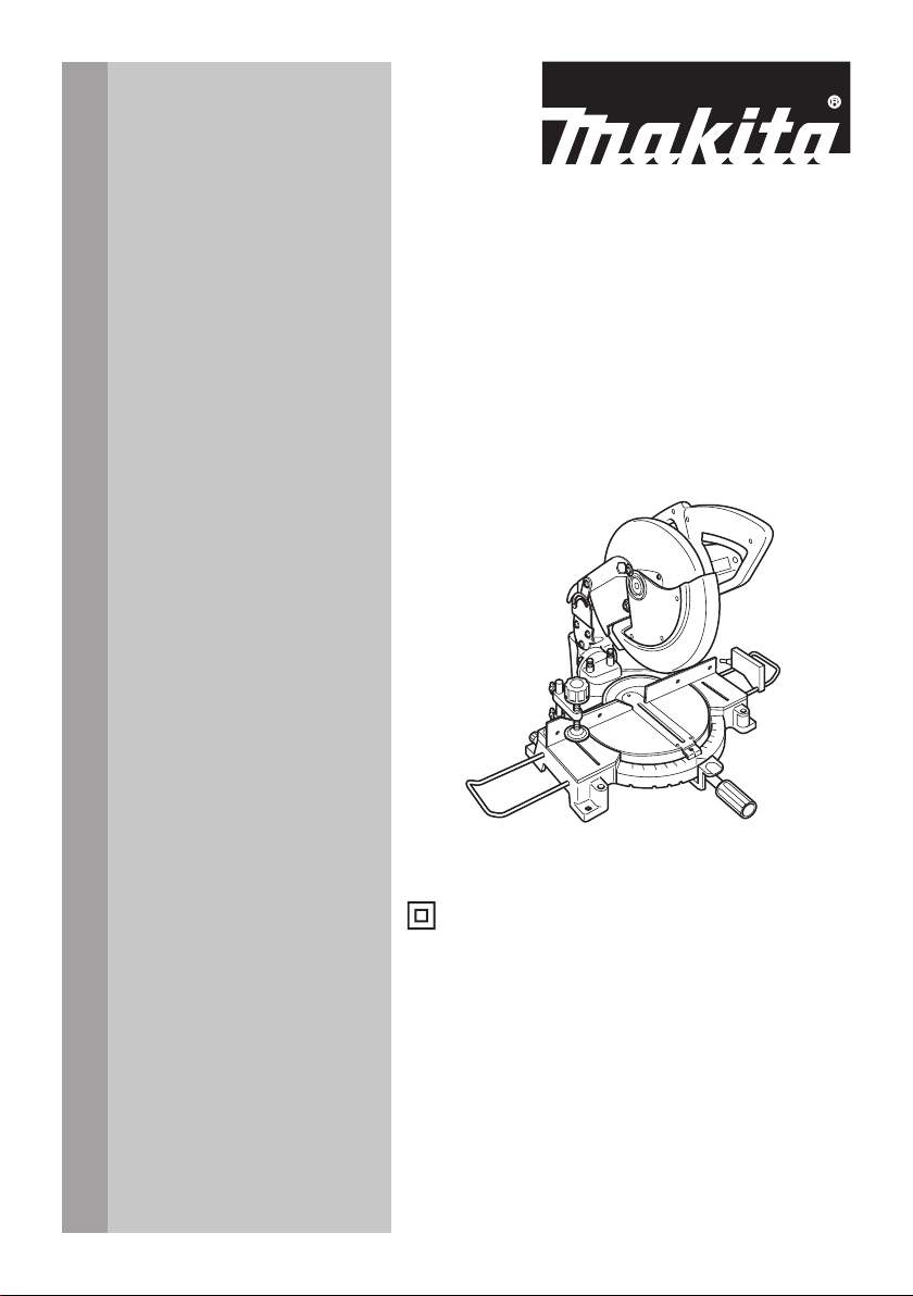
4. Do not perform any operation freehand. The
workpiece must be secured rmly against the
turn base and guide fence with a vise during
all operations. Never use your hand to secure
the workpiece.
5. Never reach around saw blade.
6. Turn off tool and wait for saw blade to stop
before moving workpiece or changing
settings.
7. Unplug tool before changing blade or
servicing.
8. Always secure all moving portions before
carrying the tool.
9. Do not use the tool in the presence of amma-
ble liquids or gases.
10. Check the blade carefully for cracks or damage
before operation. Replace cracked or damaged
blade immediately. Gum and wood pitch hard-
ened on blades slows saw and increases potential
for kickback. Keep blade clean by rst removing
it from tool, then cleaning it with gum and pitch
remover, hot water or kerosene. Never use gaso-
line to clean blade.
11. Use only anges specied for this tool.
12.
Be careful not to damage the arbor, anges
(especially the installing surface) or bolt. Damage
to these parts could result in blade breakage.
13. Make sure that the turn base is properly
secured so it will not move during operation.
Use the holes in the base to fasten the saw to a
stable work platform or bench. NEVER use tool
where operator positioning would be awkward.
14. For your safety, remove the chips, small
pieces, etc. from the table top before
operation.

4ENGLISH
15. Avoid cutting nails. Inspect for and remove all
nails from the workpiece before operation.
16. Make sure the shaft lock is released before the
switch is turned on.
17. Be sure that the blade does not contact the
turn base in the lowest position.
18. Hold the handle rmly. Be aware that the saw
moves up or down slightly during start-up and
stopping.
19. Make sure the blade is not contacting the
workpiece before the switch is turned on.
20. Before using the tool on an actual workpiece,
let it run for a while. Watch for vibration or
wobbling that could indicate poor installation
or a poorly balanced blade.
21. Wait until the blade attains full speed before
cutting.
22. Stop operation immediately if you notice any-
thing abnormal.
23. Do not attempt to lock the trigger in the "ON"
position.
24. Be alert at all times, especially during repeti-
tive, monotonous operations. Do not be lulled
into a false sense of security. Blades are
extremely unforgiving.
25. Always use accessories recommended in this
manual. Use of improper accessories such as
abrasive wheels may cause an injury.
26. NEVER hold workpiece on right side of blade
with left hand or vice versa. This is called
cross-armed cutting and exposes user to risk
of SERIOUS PERSONAL INJURY as shown
in the gure. ALWAYS use vise to secure
workpiece.
Fig.1
27. Do not abuse cord. Never yank cord to discon-
nect it from the receptacle. Keep cord away
from heat, oil, water and sharp objects.
28. NEVER stack workpieces on the table top to
speed cutting operations. Cut only one piece
at a time.
29. Some material contains chemicals which may
be toxic. Take caution to prevent dust inhala-
tion and skin contact. Follow material supplier
safety data.
SAVE THESE INSTRUCTIONS.
WARNING: MISUSE or failure to follow the
safety rules stated in this instruction manual may
cause serious personal injury.
INSTALLATION
When the tool is shipped, the handle is locked in the lowered
position by the stopper pin. Loosen the bolt with a wrench pro-
vided with the tool and move the saw head to the right angle.
Remove the bolt and secure the saw head with the knob.
1
Fig.2
► 1. Wrench
1
Fig.3
► 1. Knob
Installing auxiliary plate
Installing the auxiliary plate using the hole in the tool's
base and secure it by tightening the screw.
1
2
3
Fig.4
► 1. Auxiliary plate 2. Screw 3. Base
Bench mounting
When the tool is shipped, the handle is locked in the low-
ered position by the stopper pin. Release the stopper pin
by lowering the handle slightly and pulling the stopper pin.

5ENGLISH
1
Fig.5
► 1. Stopper pin
This tool should be bolted with four bolts to a level and
stable surface using the bolt holes provided in the tool's
base. This will help prevent tipping and possible injury.
1
Fig.6
► 1. Bolt
FUNCTIONAL
DESCRIPTION
CAUTION: Always be sure that the tool is
switched off and unplugged before adjusting or
checking function on the tool.
Blade guard
1
Fig.7
► 1. Blade guard
When lowering the handle, the blade guard rises auto-
matically. The guard is spring loaded so it returns to
its original position when the cut is completed and the
handle is raised. NEVER DEFEAT OR REMOVE THE
BLADE GUARD OR THE SPRING WHICH ATTACHES
TO THE GUARD.
In the interest of your personal safety, always maintain
the blade guard in good condition. Any irregular opera-
tion of the blade guard should be corrected immediately.
Check to assure spring loaded return action of guard.
NEVER USE THE TOOL IF THE BLADE GUARD OR
SPRING IS DAMAGED, FAULTY OR REMOVED.
DOING SO IS HIGHLY DANGEROUS AND CAN
CAUSE SERIOUS PERSONAL INJURY.
If the see-through blade guard becomes dirty, or sawdust
adheres to it in such a way that the blade and/or work-
piece is no longer easily visible, unplug the saw and clean
the guard carefully with a damp cloth. Do not use solvents
or any petroleum-based cleaners on the plastic guard.
If the blade guard is especially dirty and vision through
the guard is impaired, use the supplied wrench to
loosen the hex bolt holding the center cover. Loosen
the hex bolt by turning it counterclockwise and raise
the blade guard and center cover. With the blade guard
so positioned, cleaning can be more completely and
efciently accomplished. When cleaning is complete,
reverse procedure above and secure bolt. Do not
remove spring holding blade guard. If guard becomes
discolored through age or UV light exposure, contact
a Makita service center for a new guard. DO NOT
DEFEAT OR REMOVE GUARD.
1
Fig.8
► 1. Blade guard

6ENGLISH
Kerf board
This tool is provided with the kerf board in the turn base
to minimize tearing on the exit side of a cut. If the kerf
groove has not yet been cut in the kerf board by the
factory, you should cut the groove before actually using
the tool to cut a workpiece. Switch on the tool and lower
the blade gently to cut a groove in the kerf board.
1
Fig.9
► 1. Kerf board
Maintaining maximum cutting
capacity
This tool is factory adjusted to provide the maximum
cutting capacity for a 255 mm (10") saw blade.
When installing a new blade, always check the lower limit
position of the blade and if necessary, adjust it as follows:
First, unplug the tool. Lower the handle completely. Use
the wrench to turn the adjusting bolt until the periphery
of the blade extends slightly below the top surface of
the turn base at the point where the front face of the
guide fence meets the top surface of the turn base.
1
Fig.10
► 1. Adjusting bolt
With the tool unplugged, rotate the blade by hand while
holding the handle all the way down to be sure that
the blade does not contact any part of the lower base.
Re-adjust slightly, if necessary.
2
1
3
130mm(5-1/8")
Fig.11
►
1. Top surface of turn base 2. Periphery of blade 3. Guide fence
CAUTION: After installing a new blade,
always be sure that the blade does not contact
any part of the lower base when the handle is
lowered completely. Always do this with the tool
unplugged.
Adjusting the miter angle
1
2
Fig.12
► 1. Lock lever 2. Grip
Loosen the grip by turning counterclockwise. Turn the
turn base while pressing down the lock lever. When you
have moved the grip to the position where the pointer
points to the desired angle on the miter scale, securely
tighten the grip clockwise.
CAUTION: When turning the turn base, be
sure to raise the handle fully.
CAUTION: After changing the miter angle,
always secure the turn base by tightening the grip
rmly.

7ENGLISH
Adjusting the bevel angle
1
Fig.13
► 1. Knob
To adjust the bevel angle, loosen the knob at the rear of
the tool counterclockwise.
1
Fig.14
► 1. Pointer
Push the handle to the left to tilt the saw blade until the
pointer points to the desired angle on the bevel scale.
Then tighten the knob clockwise rmly to secure the
arm.
CAUTION: When tilting the saw blade, be sure
to raise the handle fully.
CAUTION: After changing the bevel angle,
always secure the arm by tightening the knob
clockwise.
Switch action
WARNING: Before plugging in the tool,
always check to see that the switch trigger actu-
ates properly and returns to the "OFF" position
when released. Operating a tool with a switch that
does not actuate properly can lead to loss of control
and serious personal injury.
WARNING: NEVER use tool without a fully
operative switch trigger. Any tool with an inoper-
ative switch is HIGHLY DANGEROUS and must be
repaired before further usage or serious personal
injury may occur.
1
2
Fig.15
► 1. Switch trigger 2. Hole
To start the tool, simply pull the switch trigger. Release
the switch trigger to stop.
No lock button or similar for locking the switch on is
provided on the tool, but a hole is provided for insertion
of a padlock to lock the tool off.
Electric brake
This tool is equipped with an electric blade brake. If the
tool consistently fails to quickly stop the blade after the
switch trigger is released, have the tool serviced at a
Makita service center.
CAUTION: The blade brake system is not a
substitute for the blade guard. Never use tool
without a functioning blade guard. An unguarded
blade may result in serious personal injury.
ASSEMBLY
CAUTION: Always be sure that the tool is
switched off and unplugged before carrying out
any work on the tool.
Installing or removing saw blade
CAUTION: Always be sure that the tool is
switched off and unplugged before installing or
removing the blade.
CAUTION: Use only the Makita wrench pro-
vided to install or remove the blade. Failure to
do so may result in overtightening or insufcient
tightening of the hex bolt. This could cause an
injury.
When removing or installing the blade, keep the handle
in the raised position.
To remove the blade, use the wrench to loosen the hex
bolt holding the center cover by turning it counterclock-
wise. Raise the blade guard and center cover.

8ENGLISH
1
2
Fig.16
► 1. Wrench 2. Center cover
1
Fig.17
► 1. Hex bolt
Press the shaft lock to lock the spindle and use the
wrench to loosen the hex bolt clockwise. Then remove
the hex bolt, outer ange and blade.
1
2
Fig.18
► 1. Hex bolt 2. Wrench
To install the blade, mount it carefully onto the spindle,
making sure that the direction of the arrow on the sur-
face of the blade matches the direction of the arrow on
the blade case.
12
3
4
Fig.19
► 1. Blade case 2. Arrow 3. Arrow 4. Saw blade
Install the outer ange and hex bolt, and then use the
wrench to tighten the hex bolt (left-handed) securely
counterclockwise while pressing the shaft lock.
12 4
3
5
Fig.20
► 1. Hex bolt 2. Outer ange 3. Saw blade 4. Inner
ange 5. Spindle
Return the blade guard and center cover to its original
position. Then tighten the hex bolt clockwise to secure
the center cover. Lower the handle to make sure that
the blade guard moves properly. Make sure shaft lock
has released spindle before making cut.
Dust bag
1
Fig.21
► 1. Dust bag

9ENGLISH
1
Fig.22
► 1. Fastener
The use of the dust bag makes cutting operations clean
and dust collection easy. To attach the dust bag, t it
onto the dust nozzle.
When the dust bag is about half full, remove the dust
bag from the tool and pull the fastener out. Empty
the dust bag of its contents, tapping it lightly so as to
remove particles adhering to the insides which might
hamper further collection.
NOTE: If you connect a Makita vacuum cleaner to
your saw, more efcient and cleaner operations can
be performed.
Securing workpiece
WARNING: It is extremely important to always
secure the workpiece properly and tightly with
the vise. Failure to do so can cause the tool to be
damaged and/or the workpiece to be destroyed.
PERSONAL INJURY MAY ALSO RESULT. Also,
after a cutting operation, DO NOT raise the blade
until the blade has come to a complete stop.
CAUTION: When cutting long workpieces,
use supports that are as high as the top surface
level of the turn base. Do not rely solely on the
vertical vise and/or horizontal vise to secure the
workpiece. Thin material tends to sag. Support
workpiece over its entire length to avoid blade
pinch and possible KICKBACK.
12
Fig.23
► 1. Support 2. Turn base
Vertical vise
1
2
3
4
Fig.24
► 1. Vise knob 2. Screw 3. Vise arm 4. Vise rod
The vertical vise can be installed in two positions on
either the left or right side of the guide fence. Insert the
vise rod into the hole in the guide fence and tighten the
screw to secure the vise rod.
Position the vise arm according to the thickness and
shape of the workpiece and secure the vise arm by
tightening the screw. Make sure that no part of the tool
contacts the vise when lowering the handle all the way.
If some part contacts the vise, re-position the vise.
Press the workpiece at against the guide fence and the
turn base. Position the workpiece at the desired cutting
position and secure it rmly by tightening the vise knob.
CAUTION: The workpiece must be secured
rmly against the turn base and guide fence with
the vise during all operations.
OPERATION
CAUTION: Before use, be sure to release the
handle from the lowered position by pulling the
stopper pin.
CAUTION: Make sure the blade is not con-
tacting the workpiece, etc. before the switch is
turned on.
CAUTION: Do not apply excessive pressure
on the handle when cutting. Too much force may
result in overload of the motor and/or decreased cut-
ting efciency. Press down handle with only as much
force as necessary for smooth cutting and without
signicant decrease in blade speed.
CAUTION: Gently press down the handle
to perform the cut. If the handle is pressed down
with force or if lateral force is applied, the blade may
vibrate and leave a mark (saw mark) in the workpiece
and the precision of the cut may be impaired.

10 ENGLISH
Press cutting
1
Fig.25
► 1. Vertical vise
Secure the workpiece with the vise. Switch on the tool
without the blade making any contact and wait until the
blade attains full speed before lowering. Then gently
lower the handle to the fully lowered position to cut the
workpiece. When the cut is completed, switch off the
tool and WAIT UNTIL THE BLADE HAS COME TO A
COMPLETE STOP before returning the blade to its fully
elevated position.
Miter cutting
Refer to the previously covered "Adjusting the miter
angle".
Bevel cut
Fig.26
Loosen the knob and tilt the saw blade to set the bevel
angle (Refer to the previously covered "Adjusting the
bevel angle"). Be sure to retighten the knob rmly to
secure the selected bevel angle safely. Secure the
workpiece with a vise. Switch on the tool without the
blade making any contact and wait until the blade
attains full speed. Then gently lower the handle to the
fully lowered position while applying pressure in parallel
with the blade. When the cut is completed, switch off the
tool and WAIT UNTIL THE BLADE HAS COME TO A
COMPLETE STOP before returning the blade to its fully
elevated position.
CAUTION: Always be sure that the blade will
move down to bevel direction during a bevel cut.
Keep hands out of path of saw blade.
CAUTION: During a bevel cut, it may create
a condition whereby the piece cut off will come
to rest against the side of the blade. If the blade is
raised while the blade is still rotating, this piece may
be caught by the blade, causing fragments to be scat-
tered which is dangerous. The blade should be raised
ONLY after the blade has come to a complete stop.
CAUTION: When pressing the handle down,
apply pressure parallel to the blade. If the pressure
is not parallel to the blade during a cut, the angle of
the blade might be shifted and the precision of the cut
will be impaired.
Compound cutting
Compound cutting is the process in which a bevel
angle is made at the same time in which a miter angle
is being cut on a workpiece. Compound cutting can be
performed at the angle shown in the table.
Bevel angle Miter angle
45° Left and Right 0° - 45°
When performing compound cutting, refer to “Press
cutting”, “Miter cutting” and “Bevel cut” explanations.
Cutting crown and cove moldings
Crown and cove moldings can be cut on a compound
miter saw with the moldings laid at on the turn base.
There are two common types of crown moldings and
one type of cove moldings; 52/38° wall angle crown
molding, 45° wall angle crown molding and 45° wall
angle cove molding.
123
Fig.27
► 1. 52/38° type crown molding 2. 45° type crown
molding 3. 45° type cove molding
There are crown and cove molding joints which are
made to t "Inside" 90° corners ((a) and (b) in the gure)
and "Outside" 90° corners ((c) and (d) in the gure.)

11 ENGLISH
(a) (b) (c) (d)
12
Fig.28
► 1. Inside corner 2. Outside corner
2
(a)
(b)
(a)
(b)
(b)
(a)
(b)
(a)
(a)
(b)
(c)
(d)
1
Fig.29
► 1. Inside corner 2. Outside corner
Measuring
Measure the wall width, and adjust the width of the
workpiece according to it. Always make sure that width
of the workpiece's wall contact edge is the same as wall
length.
2
3
1
4
Fig.30
► 1. Workpiece 2. Wall width 3. Width of the work-
piece 4. Wall contact edge
Always use several pieces for test cuts to check the
saw angles.
When cutting crown and cove moldings, set the bevel
angle and miter angle as indicated in the table (A) and
position the moldings on the top surface of the saw
base as indicated in the table (B).
In the case of left bevel cut
(a) (b) (c) (d)
12
Fig.31
► 1. Inside corner 2. Outside corner
Table (A)
–Molding
position
in the
gure
Bevel angle Miter angle
52/38°
type
45° type 52/38°
type
45° type
For
inside
corner
(a) Left
33.9°
Left 30° Right
31.6°
Right
35.3°
(b) Left
31.6°
Left
35.3°
For
outside
corner
(c)
(d) Right
31.6°
Right
35.3°
Table (B)
–Molding
position in
the gure
Molding
edge against
guide fence
Finished
piece
For inside
corner
(a) Ceiling
contact edge
should be
against guide
fence.
Finished
piece will be
on the Left
side of blade.
(b) Wall contact
edge should
be against
guide fence.
For outside
corner
(c) Finished
piece will be
on the Right
side of blade.(d) Ceiling
contact edge
should be
against guide
fence.
Example:
In the case of cutting 52/38° type crown molding for
position (a) in the above gure:
• Tilt and secure bevel angle setting to 33.9° LEFT.
• Adjust and secure miter angle setting to 31.6°
RIGHT.
• Lay crown molding with its broad back (hidden)
surface down on the turn base with its CEILING
CONTACT EDGE against the guide fence on the
saw.
• The nished piece to be used will always be on
the LEFT side of the blade after the cut has been
made.

12 ENGLISH
Cutting aluminum extrusion
1
2
3
4
5
Fig.32
► 1. Vise 2. Spacer block 3. Guide fence 4. Aluminum
extrusion 5. Spacer block
When securing aluminum extrusions, use spacer blocks or pieces
of scrap as shown in the gure to prevent deformation of the alu-
minum. Use a cutting lubricant when cutting the aluminum extru-
sion to prevent build-up of the aluminum material on the blade.
CAUTION: Never attempt to cut thick or round
aluminum extrusions. Thick aluminum extrusions
may come loose during operation and round alumi-
num extrusions cannot be secured rmly with this
tool.
Wood facing
WARNING: Use screws to attach the wood
facing to the guide fence. The screws should be
installed so that the screw heads are below the
surface of the wood facing so that they will not
interfere with the positioning of the material being
cut. Misalignment of the material being cut can case
unexpected movement during the cutting operation
which may result in a loss of control and serious
personal injury.
CAUTION: Use the straight wood of even
thickness as the wood facing.
Use of wood facing helps to assure splinter-free cuts
in workpieces. Attach a wood facing to the guide fence
using the holes in the guide fence.
See the gure concerning the dimensions for a sug-
gested wood facing.
≥ 10mm(3/8") ≥ 460mm(18-1/8")
11
25mm
100mm115mm 100mm115mm
(1")
(4") (4")(4-1/2") (4-1/2")
Fig.33
► 1. Holes
NOTICE: When the wood facing is attached, do
not turn the turn base with the handle lowered.
The blade and/or the wood facing will be damaged.
NOTE: The maximum cutting width will be smaller by
the width of wood facing.
Cutting repetitive lengths
When cutting several pieces of stock to the same length,
ranging from 240 mm (9-29/64") to 380 mm (15"), use
the set plate (optional accessory). Install the set plate on
the holder (optional accessory) as shown in the gure.
1
2
3
Fig.34
► 1. Set plate 2. Holder 3. Screw
Align the cutting line on your workpiece with either the left
or right side of the groove in the kerf board, and while hold-
ing the workpiece, move the set plate ush against the end
of the workpiece. Then secure the set plate with the screw.
When the set plate is not used, loosen the screw and
turn the set plate out of the way.
NOTE: Use of the holder-rod assembly (optional
accessory) allows cutting repetitive lengths up to
2,200 mm (7.2ft) approximately.
Carrying tool
1
Fig.35
► 1. Stopper pin
Make sure that the tool is unplugged. Secure the blade
at 0° bevel angle and the turn base at left miter angle
fully. Lower the handle fully and lock it in the lowered
position by pushing in the stopper pin.
Carry the tool by carrying grip as shown in the gure. If
you remove the holders, dust bag, etc., you can carry
the tool more easily.

13 ENGLISH
Fig.36
CAUTION: Always secure all moving portions
before carrying the tool.
CAUTION: Stopper pin is for carrying and
storage purposes only and not for any cutting
operations.
MAINTENANCE
WARNING: Always be sure that the blade is
sharp and clean for the best and safest perfor-
mance. Attempting a cut with a dull and /or dirty blade
may cause kickback and result in a serious personal
injury.
CAUTION: Always be sure that the tool is
switched off and unplugged before attempting to
perform inspection or maintenance.
NOTICE: Never use gasoline, benzine, thinner,
alcohol or the like. Discoloration, deformation or
cracks may result.
Adjusting the cutting angle
This tool is carefully adjusted and aligned at the factory,
but rough handling may have affected the alignment. If
your tool is not aligned properly, perform the following:
Miter angle
11
Fig.37
► 1. Hex bolt
Loosen the grip which secures the turn base. Turn the
turn base so that the pointer points to 0° on the miter
scale. Tighten the grip and loosen the hex bolts secur-
ing the guide fence using the wrench. If the pointer
does not point to 0° on the miter scale, loosen the screw
which secures the pointer and move and secure the
pointer plate so that the pointer points to 0° on the miter
scale.
Lower the handle fully and lock it in the lowered position
by pushing in the stopper pin. Square the side of the
blade with the face of the guide fence using a triangular
rule, try-square, etc. Then securely tighten the hex bolts
on the guide fence in the order from the right side.
1
Fig.38
► 1. Triangular rule
Bevel angle
0° bevel angle
1
Fig.39
► 1. 0° bevel angle adjusting bolt
Lower the handle fully and lock it in the lowered position
by pushing in the stopper pin.
Loosen the knob at the rear of the tool.
Loosen the hex nut and turn the 0° bevel angle adjust-
ing bolt on the right side of the turn base two or three
revolutions clockwise to tilt the blade to the right.
Carefully square the side of the blade with the top
surface of the turn base using the triangular rule, try-
square, etc. by turning the 0° bevel angle adjusting bolt
counterclockwise. Then tighten the hex nut to secure
the 0° bevel angle adjusting bolt and tighten the knob
securely.
Make sure that the pointer on the arm points to 0° on
the bevel scale. If it does not point to 0° on the bevel
scale, loosen the screw which secures the pointer and
move and secure the pointer plate so that the pointer
points to 0° on the bevel scale.

14 ENGLISH
1
2
3
Fig.40
► 1. Triangular rule 2. Saw blade 3. Top surface of
turn base
1
Fig.41
► 1. Pointer
45° bevel angle
1
2
Fig.42
► 1. 45° bevel angle adjusting bolt 2. Pointer
Adjust the 45° bevel angle only after performing 0°
bevel angle adjustment.
To adjust left 45° bevel angle, loosen the knob and tilt
the blade to the left fully.
Make sure that the pointer on the arm points to 45° on
the bevel scale on the arm.
If the pointer does not point to 45°, turn the 45° bevel
angle adjusting bolt on the left side of the arm until the
pointer points to 45°.
Replacing carbon brushes
Fig.43
Remove and check the carbon brushes regularly.
Replace when they wear down to 3 mm (1/8") in length.
Keep the carbon brushes clean and free to slip in the
holders. Both carbon brushes should be replaced at the
same time. Use only identical carbon brushes.
Use a screwdriver to remove the brush holder caps.
Take out the worn carbon brushes, insert the new ones
and secure the brush holder caps.
1
2
Fig.44
► 1. Brush holder cap 2. Screwdriver
After use
After use, wipe off chips and dust adhering to the tool
with a cloth or the like. Keep the blade guard clean
according to the directions in the previously covered
section titled "Blade guard". Lubricate the sliding por-
tions with machine oil to prevent rust.
To maintain product SAFETY and RELIABILITY,
repairs, any other maintenance or adjustment should
be performed by Makita Authorized or Factory Service
Centers, always using Makita replacement parts.

15 ENGLISH
MAKITA LIMITED ONE YEAR
WARRANTY
Warranty Policy
Every Makita tool is thoroughly inspected and tested
before leaving the factory. It is warranted to be free of
defects from workmanship and materials for the period
of ONE YEAR from the date of original purchase.
Should any trouble develop during this one year period,
return the COMPLETE tool, freight prepaid, to one
of Makita’s Factory or Authorized Service Centers. If
inspection shows the trouble is caused by defective
workmanship or material, Makita will repair (or at our
option, replace) without charge.
This Warranty does not apply where:
• repairs have been made or attempted by others:
• repairs are required because of normal wear and
tear:
• the tool has been abused, misused or improperly
maintained:
• alterations have been made to the tool.
IN NO EVENT SHALL MAKITA BE LIABLE FOR ANY
INDIRECT, INCIDENTAL OR CONSEQUENTIAL
DAMAGES FROM THE SALE OR USE OF THE
PRODUCT. THIS DISCLAIMER APPLIES BOTH
DURING AND AFTER THE TERM OF THIS
WARRANTY.
MAKITA DISCLAIMS LIABILITY FOR ANY IMPLIED
WARRANTIES, INCLUDING IMPLIED WARRANTIES
OF "MERCHANTABILITY" AND "FITNESS FOR A
SPECIFIC PURPOSE," AFTER THE ONE YEAR TERM
OF THIS WARRANTY.
This Warranty gives you specic legal rights, and you
may also have other rights which vary from state to
state. Some states do not allow the exclusion or lim-
itation of incidental or consequential damages, so the
above limitation or exclusion may not apply to you.
Some states do not allow limitation on how long an
implied warranty lasts, so the above limitation may not
apply to you.

16 FRANÇAIS
FRANÇAIS (Mode d’emploi original)
SPÉCIFICATIONS
Modèle : M2300
Diamètre de la lame 255 mm (10")
Diamètre de l’orice 15,88mm (5/8")
Angle d’onglet max. Gauche 45°, Droite 45°
Angle de biseau max. 45° à gauche
Vitesse à vide (T/MIN) 4 200 /min
Dimensions (L x P x H) 610 mm x 485 mm x 515 mm
(24" x 19-3/32" x 20-1/4")
Poids net 14,7 kg (32,5 lbs)
Capacités de coupe maximales (H x P) avec une lame de 255 mm de diamètre
Angle de coupe en biseau Angle de coupe d’onglet
0° 45° (gauche et droite)
0° 75 mm x 130 mm
(2-15/16″ x 5-1/8″)
75 mm x 90 mm
(2-15/16″ x 3-9/16″)
45° (gauche) 48 mm x 120 mm
(1-7/8″ x 4-3/4″)
48 mm x 90 mm
(1-7/8″ x 3-9/16″)
• Étant donné l’évolution constante de notre programme de recherche et de développement, les spécications
contenues dans ce manuel sont sujettes à modication sans préavis.
• Les spécications peuvent varier suivant les pays.
• Poids conforme à la procédure EPTA du 01/2003
Pour votre propre sécurité, veuil-
lez lire le manuel d’instructions
Avant d’utiliser l’outil.
Conservez-le pour référence
ultérieure.
Précautions générales (pour tous
les outils)
1. VOUS DEVEZ CONNAÎTRE VOTRE OUTIL
ÉLECTRIQUE. Lisez attentivement le manuel
de l’utilisateur. Familiarisez-vous avec les
applications et limites de l’outil, ainsi qu’avec
les risques potentiels qui lui sont spéciques.
2. MAINTENEZ LES PROTECTEURS EN PLACE et
en bon état de fonctionnement.
3. RETIREZ LES CLÉS DE RÉGLAGE ET DE
SERRAGE. Prenez l’habitude de vous assu-
rer que les clés de réglage et de serrage ont
été retirées de l’outil avant de le mettre sous
tension.
4. MAINTENEZ LA ZONE DE TRAVAIL PROPRE.
Les zones de travail et les établis encombrés
ouvrent grande la porte aux accidents.
5. ÉVITEZ L’UTILISATION DANS UN
ENVIRONNEMENT DANGEREUX. N’utilisez
pas les outils électriques dans les endroits
humides ou mouillés, et ne les exposez pas à
la pluie. Maintenez un éclairage adéquat dans
la zone de travail. N’utilisez pas votre outil en
présence de liquides ou gaz inammables.
6. TENEZ LES ENFANTS À L’ÉCART. Toute autre
personne que l’utilisateur de l’outil doit se
tenir à une distance sûre de la zone de travail.
7. FAITES EN SORTE QUE L’ATELIER SOIT SANS
DANGER POUR LES ENFANTS, en y posant
des cadenas, un interrupteur principal, ou en
retirant les clés de démarrage.
8. NE FORCEZ PAS L’OUTIL. Il effectuera un tra-
vail de meilleure qualité et plus sécuritaire s’il
est utilisé au régime pour lequel il a été conçu.
9. UTILISEZ LE BON OUTIL. Ne forcez pas un
outil ou accessoire à effectuer un travail pour
lequel il n’a pas été conçu.
10. PORTEZ DES VÊTEMENTS ADÉQUATS. Ne
portez ni vêtements ni gants amples, ni cra-
vate, anneaux/bagues, bracelets ou autres
bijoux susceptibles d’être happés par les
pièces mobiles de l’outil. Le port de chaus-
sures antidérapantes est recommandé. Portez
un let de protection pour envelopper les
cheveux longs.
11. PORTEZ TOUJOURS DES LUNETTES DE
SÉCURITÉ. Si le travail de coupe dégage de la
poussière, portez également un écran facial
ou un masque antipoussières. Les lunettes
ordinaires ne sont munies que de lentilles
résistances aux chocs; elles ne constituent
PAS des lunettes de sécurité.
12. FIXEZ BIEN LA PIÈCE. Lorsque cela est pos-
sible, xez la pièce à travailler à l’aide de dis-
positifs de serrage ou d’un étau. Cela est plus
sécuritaire que l’utilisation de la main et libère
les deux mains pour le maniement de l’outil.

17 FRANÇAIS
13. NE VOUS ÉTIREZ PAS TROP. Assurez-vous
d’une bonne prise au sol et d’une bonne posi-
tion d’équilibre en tout temps.
14. PRENEZ SOIN DES OUTILS. Maintenez les
outils bien aiguisés et propres pour assurer un
fonctionnement sécuritaire et un rendement
optimal. Suivez les instructions de lubrica-
tion et de changement des accessoires.
15. DÉBRANCHEZ LES OUTILS avant tout travail
de réparation ou avant de changer les acces-
soires tels que lames, embouts, couteaux et
autres.
16. RÉDUISEZ LES RISQUES DE DÉMARRAGE
ACCIDENTEL. Assurez-vous que l’interrup-
teur est en position d’arrêt avant de brancher
l’outil.
17. UTILISEZ LES ACCESSOIRES
RECOMMANDÉS. Consultez le manuel de l’uti-
lisateur pour savoir quels sont les accessoires
recommandés. L’utilisation d’accessoires
non adéquats peut comporter un risque de
blessure.
18. NE VOUS APPUYEZ JAMAIS SUR L’OUTIL.
Vous courez un risque de blessure grave si
l’outil bascule ou si vous touchez accidentelle-
ment l’outil tranchant.
19. VÉRIFIEZ S’IL Y A DES PIÈCES
ENDOMMAGÉES. Avant d’utiliser l’outil, tout
protecteur ou dispositif endommagé doit être
vérié soigneusement an de s’assurer qu’il
fonctionne adéquatement et peut remplir la
fonction pour laquelle il est conçu. Vériez si
les pièces mobiles sont bien alignées et bien
xées, vériez la présence de pièces brisées,
vériez que l’outil est bien monté et assu-
rez-vous que rien ne peut entraver son bon
fonctionnement. Un protecteur ou tout autre
dispositif endommagé doit être adéquatement
réparé ou remplacé.
20. SENS D’ALIMENTATION. Vous devez faire
avancer la pièce à l’encontre de la lame ou de
l’outil tranchant, non la faire progresser dans
le même sens.
21. NE LAISSEZ JAMAIS SANS SURVEILLANCE
UN OUTIL EN MARCHE. COUPEZ LE
CONTACT. Attendez que l’outil se soit complè-
tement arrêté avant de le quitter.
22. PIÈCES DE RECHANGE Seules des pièces de
rechange identiques aux originales doivent
être utilisées lors des réparations.
23. FICHES POLARISÉES Pour réduire les risques
de décharge électrique, cet équipement est
muni d’une che polarisée (une des lames est
plus large que l’autre). Cette che ne peut être
insérée dans une prise polarisée que dans un
seul sens. Si la che ne s’insère pas à fond
dans la prise, insérez-la en sens inverse. Si
elle ne s’insère toujours pas à fond, contactez
un technicien qualié pour faire installer une
prise appropriée. N’apportez aucune modica-
tion à la che.
MISE EN GARDE RELATIVE À LA TENSION : Avant
de brancher l’outil sur une source d’alimentation
(prise ou autre dispositif), assurez-vous que la
tension du circuit correspond à celle qui est spéci-
ée sur la plaque signalétique de l’outil. L’utilisation
d’une source d’alimentation dont la tension est
supérieure à celle spéciée pour l’outil peut entraî-
ner une GRAVE BLESSURE et endommager l’outil.
En cas de doute, NE BRANCHEZ PAS L’OUTIL.
L’utilisation d’une source d’alimentation dont la ten-
sion est inférieure à la valeur indiquée sur la plaque
signalétique endommagera le moteur.
UTILISEZ UN CORDON PROLONGATEUR
ADÉQUAT. Assurez-vous que le cordon prolon-
gateur est en bon état. Lors de l’utilisation d’un
cordon prolongateur, utilisez sans faute un cordon
assez gros pour conduire le courant que le produit
nécessite. Un cordon trop petit provoquera une
baisse de tension de secteur, résultant en une
perte de puissance et une surchauffe. Le Tableau 1
indique la dimension appropriée de cordon selon
sa longueur et selon l’intensité nominale indiquée
sur la plaque signalétique. En cas de doute sur un
cordon donné, utilisez le cordon suivant. Plus le
numéro de gabarit indiqué est petit, plus le cordon
est gros.
Tableau 1 : Calibre minimum du cordon
Intensité nominale Volts Longueur totale du cordon en pieds
120 V 25 ft. 50 ft. 100 ft. 150 ft.
220 V - 240 V 50 ft. 100 ft. 200 ft. 300 ft.
Plus de Pas plus de Calibre américain des ls
06–18 16 16 14
610 18 16 14 12
10 12 16 16 14 12
12 16 14 12 Non recommandé
Règles de sécurité supplémentaires
NE vous laissez PAS tromper (au l d’une utilisation
répétée) par un sentiment d’aisance et de familiarité
avec le produit, en négligeant le respect rigoureux
des consignes de sécurité qui accompagnent la scie
à onglets. L’utilisation non sécuritaire ou incorrecte
de cet outil comporte un risque de blessure grave.
1. Portez un protecteur pour la vue.
2. Maintenez les mains hors de la ligne de coupe
de la lame de scie. Évitez tout contact avec
la lame lorsqu’elle continue de tourner après
la mise hors tension de l’outil. Elle peut alors
quand même causer de graves blessures.

18 FRANÇAIS
3. N’utilisez jamais la scie sans les protecteurs
en place. Assurez-vous avant chaque utili-
sation que le protège-lame se referme bien.
N’utilisez pas la scie si le protège-lame ne se
déplace pas librement et ne se referme pas
instantanément. Ne xez ou n’attachez jamais
le protège-lame en position ouverte.
4. N’effectuez aucune opération en tenant la
pièce à travailler uniquement avec la main. La
pièce doit être xée fermement contre le socle
rotatif et le garde de guidage avec un étau lors
de toutes les opérations. N’utilisez jamais la
main pour immobiliser la pièce.
5. N’approchez jamais les mains de la lame de
scie.
6. Coupez le contact et attendez l’arrêt de la lame
de scie avant de déplacer la pièce ou de modi-
er les réglages.
7. Débranchez l’outil avant le changement de
lame ou la réparation.
8. Fixez toujours les composants mobiles de
l’outil avant de le transporter.
9. N’utilisez pas l’outil en présence de liquides
ou gaz inammables.
10. Avant l’utilisation, vériez toujours soigneuse-
ment l’absence de ssures ou de dommages
sur la lame. Veuillez remplacer immédiatement
toute lame ssurée ou endommagée. La pré-
sence de résine et de goudron sur la lame ralentit
la scie et entraîne une augmentation des risques
de rebond. Pour nettoyer la lame, retirez-la
d’abord de l’outil, puis utilisez un décapant, de
l’eau chaude ou du kérosène pour retirer la résine
et le goudron. N’utilisez jamais d’essence pour
nettoyer la lame.
11. Utilisez exclusivement les asques spéciés
pour cet outil.
12.
Prenez garde d’endommager l’arbre, les asques
(tout particulièrement leur surface d’installation)
ou le boulon. L’endommagement de ces pièces
peut causer une cassure de la lame.
13. Assurez-vous que le socle rotatif est bien
immobilisé, de sorte qu’il ne bouge pas pen-
dant l’opération. Fixez la scie à une surface
de travail ou à un établi stable au moyen des
trous du socle. N’utilisez JAMAIS l’outil si
vous vous trouvez dans une position qui n’as-
sure pas une pleine liberté de mouvement.
14. Pour votre sécurité, retirez les copeaux et
autres petites pièces présentes sur la table
avant de commencer le travail.
15. Évitez les clous. Avant de travailler votre
pièce, inspectez-la et retirez-en tous les clous.
16. Assurez-vous que le blocage de l’arbre est
libéré avant de mettre le contact.
17. Assurez-vous que la lame n’entre pas en
contact avec le socle rotatif lorsqu’elle se
trouve sur sa position la plus basse.
18. Tenez la poignée fermement. N’oubliez pas
que la scie se déplace légèrement vers le haut
ou le bas au démarrage et à l’arrêt.
19. Assurez-vous que la lame n’entre pas en
contact avec la pièce avant de mettre l’outil
sous tension.
20. Avant d’utiliser l’outil sur la pièce, laissez-le
tourner à vide un instant. Soyez attentif à toute
vibration ou tout sautillement pouvant indi-
quer que la lame n’est pas bien installée ou est
mal équilibrée.
21. Attendez que la lame atteigne sa pleine vitesse
avant de procéder à la coupe.
22. Arrêtez immédiatement votre outil dès que
vous observez quelque chose d’anormal.
23. N’essayez pas de verrouiller la gâchette en
position de marche.
24. Demeurez attentif en tout temps, et tout par-
ticulièrement lors des travaux répétitifs et
monotones. Ne vous laissez pas emporter par
un sentiment de sécurité trompeur. Les lames
ne pardonnent pas.
25. Utilisez toujours les accessoires recomman-
dés dans le présent manuel. L’utilisation
d’accessoires inadéquats, tels que les meules
abrasives par exemple, peut entraîner une
blessure.
26. Ne tenez JAMAIS la pièce du côté droit de
la lame avec la main gauche, et vice versa.
Cela s’appelle une coupe à bras croisé et
expose l’utilisateur à un RISQUE DE GRAVE
BLESSURE, tel qu’indiqué sur l’illustration.
Utilisez TOUJOURS un étau pour immobiliser
la pièce.
Fig.1
27. Ne maltraitez pas le cordon. Ne donnez jamais
de coup sec sur le cordon pour le débrancher
de la prise de courant. Gardez le cordon à
l’écart de la chaleur, de l’huile, de l’eau et des
objets tranchants.
28. N’empilez JAMAIS plusieurs pièces sur la table
de travail pour accélérer le travail de coupe.
Coupez les pièces une à la fois.
29. Certains matériaux contiennent des produits
chimiques qui peuvent être toxiques. Prenez
les précautions nécessaires pour éviter l’inha-
lation des poussières ou leur contact avec la
peau. Conformez-vous aux consignes de sécu-
rité du fournisseur du matériau.
CONSERVEZ CE MODE
D’EMPLOI.
MISE EN GARDE : Une MAUVAISE
UTILISATION de l’outil ou l’ignorance des
consignes de sécurité du présent manuel d’ins-
tructions peuvent entraîner une grave blessure.

19 FRANÇAIS
POSE
À la sortie d’usine de l’outil, sa poignée est verrouillée en position
abaissée par la broche de blocage. Desserrez le boulon à l’aide
de la clé fournie avec l’outil et déplacez la tête de scie sur l’angle
droit. Retirez le boulon et xez la tête de scie à l’aide du bouton.
1
Fig.2
► 1. Clé
1
Fig.3
► 1. Bouton
Pose de la plaque auxiliaire
Posez la plaque auxiliaire au moyen de l’orice du socle
de l’outil, et xez-la en serrant la vis.
1
2
3
Fig.4
► 1. Plaque auxiliaire 2. Vis 3. Socle
Montage du banc
À la sortie d’usine de l’outil, sa poignée est verrouillée en position
abaissée par la broche de blocage. Libérez la broche de blocage en
abaissant légèrement la poignée et en tirant sur la broche de blocage.
1
Fig.5
► 1. Broche de blocage
Cet outil doit être boulonné par quatre boulons à une
surface plane et stable, à l’aide des trous de boulons
prévus à cet effet sur le socle de l’outil. Cela contribuera
à prévenir les risques de basculement et de blessure.
1
Fig.6
► 1. Boulon

20 FRANÇAIS
DESCRIPTION DU
FONCTIONNEMENT
ATTENTION : Assurez-vous toujours que
l’outil est hors tension et débranché avant de
l’ajuster ou de vérier son fonctionnement.
Protège-lame
1
Fig.7
► 1. Protège-lame
Lorsque vous abaissez la poignée, le protège-lame
s’élève automatiquement. Le protège-lame est main-
tenu par un ressort et revient donc à sa position d’ori-
gine lorsque la coupe est terminée et que vous relevez
la poignée. NE NEUTRALISEZ ET NE RETIREZ
JAMAIS LE PROTÈGE-LAME NI LE RESSORT QUI Y
EST FIXÉ.
Pour votre propre sécurité, gardez toujours le pro-
tège-lame en bon état. Tout fonctionnement irrégulier
du protège-lame doit être corrigé immédiatement.
Assurez-vous que l’action de retour du protège-lame
par son ressort s’effectue correctement. N’UTILISEZ
JAMAIS L’OUTIL SI LE PROTÈGE-LAME OU LE
RESSORT EST ENDOMMAGÉ, DÉFECTUEUX OU
RETIRÉ. CELA EST EXTRÊMEMENT DANGEREUX
ET PEUT CAUSER UNE GRAVE BLESSURE.
Si le protège-lame transparent se salit, ou si de la pous-
sière s’y colle et que la lame et/ou la pièce n’est plus
bien visible, débranchez la scie et nettoyez soigneuse-
ment le protège-lame avec un linge humide. N’utilisez
aucun solvant ou nettoyant à base de pétrole pour
nettoyer le protège-lame de plastique.
Si les saletés sont telles qu’il n’est plus possible de voir
à travers le protège-lame, utilisez la clé fournie pour
desserrer le boulon hexagonal qui retient le couvercle
central. Desserrez le boulon hexagonal en le tournant
dans le sens contraire des aiguilles d’une montre, et
soulevez le protège-lame et le couvercle central. Avec
le protège-lame dans cette position, vous pourrez
effectuer le nettoyage de manière plus complète et
efcace. Une fois le nettoyage terminé, effectuez la
procédure inverse de celle ci-dessus et xez le boulon.
Ne retirez pas le ressort qui retient le protège-lame.
Si le protège-lame se décolore avec le temps ou sous
l’effet des rayons ultraviolets, contactez un centre de
service après-vente Makita pour le faire remplacer par
un neuf. NE NEUTRALISEZ PAS ET NE RETIREZ PAS
LE PROTÈGE-LAME.
1
Fig.8
► 1. Protège-lame
Plateau de découpe
Le socle rotatif de cet outil est équipé d’un plateau de
découpe pour réduire la déchirure du côté extérieur de
la coupe. Si la rainure du plateau de découpe n’a pas
été pratiquée sur le plateau de découpe en usine, vous
devez le faire vous-même avant d’utiliser l’outil pour
couper une pièce. Mettez l’outil sous tension et abais-
sez doucement la lame pour pratiquer une rainure dans
le plateau de découpe.
1
Fig.9
► 1. Plateau de découpe
Maintien de la capacité de coupe
maximale
Cet outil est réglé en usine de sorte que sa capacité de
coupe maximale soit atteinte avec une lame de scie de
255 mm (10″).
Lorsque vous installez une nouvelle lame, vériez
toujours la position limite inférieure de la lame et, au
besoin, réglez-la comme suit :
Débranchez d’abord l’outil. Abaissez complètement la
poignée. À l’aide de la clé, tournez le boulon de réglage
jusqu’à ce que le bord de la lame se trouve légèrement
sous la surface du socle rotatif, là où la face avant du
garde de guidage rencontre la face supérieure du socle
rotatif.
Other manuals for M2300
5
Table of contents
Languages:
Other Makita Saw manuals

Makita
Makita DJR186 User manual

Makita
Makita HS7611J User manual

Makita
Makita JR3051T User manual

Makita
Makita 5402NA User manual

Makita
Makita LH1201FL User manual

Makita
Makita LS1016 User manual

Makita
Makita DPB184 User manual

Makita
Makita MAKSTAR BJR240SH Manual

Makita
Makita 2414DB User manual

Makita
Makita BPB180 User manual

Makita
Makita DJR186 User manual

Makita
Makita LS0714 User manual

Makita
Makita DRS780 User manual

Makita
Makita DPB184 User manual

Makita
Makita MT560 User manual

Makita
Makita LS1216 User manual

Makita
Makita SR1800 User manual

Makita
Makita DJR187 User manual

Makita
Makita SP001G User manual

Makita
Makita DLS600 User manual