Makita ER2650LH User guide

ER2650LH
Original Instruction Manual
Instructions d’emploi d’origine
Originalbetriebsanleitung
Manuale di istruzioni originale
Originele gebruiksaanwijzing
Instrucciones de manejo originales
Instruções de serviço original
Original brugsanvisning
Important:
Read this instruction manual carefully before putting the Petrol String Trimmer into operation and strictly observe the safety regulations!
Preserve instruction manual carefully!
Important :
Veuillez lire attentivement ce mode d’emploi avant d’utiliser la débroussailleuse thermique, et observez strictement les consignes de sécurité !
Veillez à conservez ce mode d’emploi !
Wichtig:
Lesen Sie vor Verwendung des Motor-Rasentrimmers diese Betriebsanleitung aufmerksam durch und halten Sie die Sicherheitsregeln strikt ein!
Bewahren Sie diese Betriebsanleitung sorgfältig auf!
Importante:
Leggere attentamente il presente manuale di istruzioni prima di mettere in funzione il tagliabordi a benzina e rispettare rigorosamente le
normative sulla sicurezza.
Conservare con cura il manuale di istruzioni.
Belangrijk:
Lees deze gebruiksaanwijzing aandachtig door voordat u de benzinegraskantmaaier in gebruik neemt en houdt u te allen tijde aan de
veiligheidsinstructies!
Bewaar deze gebruiksaanwijzing zorgvuldig!
Importante:
Lea atentamente este manual de instrucciones antes de utilizar la desbrozadora y cumpla estrictamente la normativa de seguridad.
Conserve el manual de instrucciones con cuidado.
Importante:
Leia cuidadosamente este manual de instruções antes de utilizar a Roçadeira A Gasolina e cumpra todas as normas de segurança!
Guarde este manual de instruções num local seguro!
Vigtigt:
Læs denne brugsanvisning omhyggeligt igennem inden du anvender den benzindrevne trådtrimmer og overhold sikkerhedsregulativerne til
mindste detalje!
Gem denne brugsanvisning omhyggeligt!
Önemli:

2
Thank you very much for purchasing the MAKITA Outdoor Power Equipment.
We are pleased to recommend to you the MAKITA product which is the result of
a long development program and many years of knowledge and experience.
Please read this booklet which refers in detail to the various points that will
demonstrate its outstanding performance. This will assist you to obtain the best
possible result from your MAKITA product.
Table of Contents Page
SYMBOLS
English (Original instructions)
Symbols.........................................................................2
Safety instructions .........................................................3
Technical data................................................................6
Designation of parts.......................................................7
Mounting of handle........................................................8
Mounting of protector.....................................................8
Mounting of nylon cutting head......................................8
Before start of operation................................................9
Points in operation and how to stop ............................ 11
The nylon cutting head ................................................12
Servicing instructions...................................................14
Storage........................................................................17
Read instruction manual and follow the
warnings and safety precautions!
Take Particular care and attention!
Forbidden!
Keep distance!
Flying object hazard!
No smoking!
Protective gloves must be worn!
Wear sturdy boots with nonslip soles.
Steeltoed safety boots are recommended!
Keep the area of operation clear of all
persons and pets!
Wear protective helmet, eye and ear
protection.
Top permissible tool speed
Fuel (Gasoline)
Engine-manual start
Emergency stop
First Aid
ON/START
OFF/STOP
Never use metal blades

3
360°
15 Meters
SAFETY INSTRUCTIONS
General Instructions
Read this instruction manual to become familiar with handling of the–
well as others due to improper handling.
It is recommended only to lend the equipment to people who have proven to–
be experienced.
Always hand over the instruction manual.
First users should ask the dealer for basic instructions to familiarize oneself–
with the handling of string trimmers.
Children and young persons aged under 18 years must not be allowed to–
operate this equipment. Persons over the age of 16 years may however
use the device for the purpose of being trained while under supervision of a
Use with the utmost care and attention.–
Operate only if you are in good physical condition. Perform all work calmly–
and carefully. The user has to accept liability for others.
Never use this equipment after consumption of alcohol or drugs, or if feeling–
tired or ill.
National regulation can restrict the use of the machine.–
Intended use of the machine
This equipment is only intended for cutting grass and light weeds. It should–
not be used for any other purpose such as edging or hedge cutting as this
may cause injury.
Personal protective equipment
The clothing worn should be functional and appropriate, i.e. it should be tight-–
could become entangled with bushes or shrubs.
In order to avoid either head-, eye-, hand- or foot injuries as well as to protect–
your hearing the following protective equipment and protective clothing must
be used during operation.
Always wear a helmet where there is a risk of falling objects. The protective–
helmet (1) is to be checked at regular intervals for damage and is to be
replaced at the latest after 5 years. Use only approved protective helmets.
The visor (2) of the helmet (or alternatively goggles) protects the face from–
prevent eye injuries.
Wear adequate noise protection equipment to avoid hearing impairment (ear–
muffs (3), ear plugs etc.).
–
We strongly recommend that the user wears work overalls.
Gloves (5) are part of the prescribed equipment and must always be worn–
during operation.
When using the equipment, always wear sturdy shoes (6) with a non-slip–
sole. This protects against injuries and ensures a good footing.
Starting up the Petrol String Trimmer
Please make sure that there are no children or other people within a working–
range of 15 meters (50 ft), also pay attention to any animals in the working
vicinity.
Before use always check the equipment is safe for operation:–
Check the security of the cutting attachment, the throttle lever for easy action
and check for proper functioning of the throttle lever lock.
Rotation of the cutting attachment during idling speed is not allowed. Check–
with your dealer for adjustment if in doubt. Check for clean and dry handles
and test the function of the start/stop switch.

4
Resting
Transport
Refueling
Maintenance
Tool replacement
3 meters
Start the Petrol String Trimmer only in accordance with the instructions.–
Do not use any other methods for starting the engine!–
Use the Petrol String Trimmer and the tools only for such applications as–
Only start the engine, after the entire assembly is done. Operation of the–
device is only permitted after all the appropriate accessories are attached!
Before starting make sure that the cutting attachment has no contact with–
hard objects such as branches, stones etc. as the cutting attachment will
revolve when starting.
The engine is to be switched off immediately in case of any engine problems.–
Should the cutting attachment hit stones or other hard objects, immediately–
switch off the engine and inspect the cutting attachment.
Inspect the cutting attachment at short regular intervals for damage (detection–
of hairline cracks by means of tapping-noise test).
If the equipment gets heavy impact or fall, check the condition before–
continuing work. Check the fuel system for fuel leakage and the controls
and safety devices for malfunction. If there is any damage or doubt, ask our
authorized service center for the inspection and repair.
During operation always hold the Petrol String Trimmer with both hands.–
Never hold the Petrol String Trimmer with one hand during use.
Always ensure a safe footing.
Operate the equipment in such a manner as to avoid inhalation of the exhaust–
gases. Never run the engine in enclosed rooms (risk of gas poisoning).
Carbon monoxide is an odorless gas.
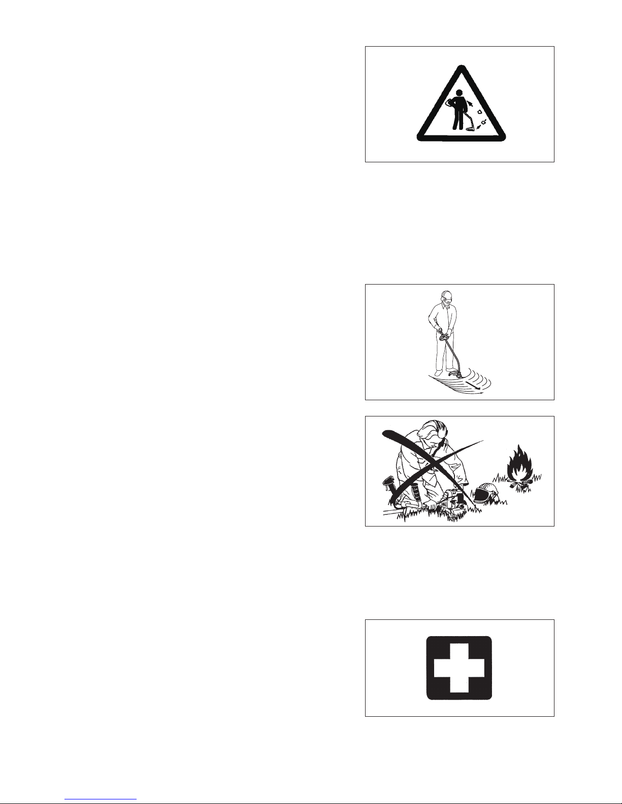
Switch off the engine when resting and when leaving the equipment–
unattended, and place it in a safe location to prevent danger to others or
damage to the machine.
Never put the hot Petrol String Trimmer onto dry grass or onto any–
combustible materials.
Always install the approved cutting attachment guard onto the equipment–
before starting the engine. Otherwise contact with the cutting attachment may
cause serious injury.
All protective installations and guards supplied with the machine must be–
used during operation.
–
Shut off the engine during transport.–
Ensure safe position of the equipment during car transportation to avoid fuel–
leakage.
When transporting, ensure that the fuel tank is completely empty.–
When unloading the equipment from the truck, never drop the Engine to the–
ground or this may severely damage the fuel tank.
Except in case of emergency, never drop or cast the equipment to the ground–
or this may severely damage the equipment.
Remember to lift the entire equipment from the ground when moving the–
equipment. Dragging the fuel tank is highly dangerous and will cause damage
Refueling
–
smoke.
Avoid skin contact with mineral oil products. Do not inhale fuel vapor. Always–
wear protective gloves during refueling. Change and clean protective clothing
at regular intervals.
Take care not to spill either fuel or oil in order to prevent soil contamination–
(environmental protection). Clean the Petrol String Trimmer immediately after
fuel has been spilt.
Avoid any fuel contact with your clothing. Change your clothing instantly if–
Inspect the fuel cap at regular intervals making sure that it can be securely–
fastened and does not leak.
Carefully tighten the fuel tank cap. Change location to start the engine (at–
least 3 meters away from the place of refueling).
Never refuel in closed rooms. Fuel vapors accumulate at ground lever (risk of–
explosions).
Only transport and store fuel in approved containers. Make sure the fuel–
stored is not accessible to children.

5
Method of operation
Only use in good light and visibility. During the winter season beware of–
slippery or wet areas, ice and snow (risk of slipping). Always ensure a safe
footing.
Never cut above waist height.–
Never stand on a ladder.–
Never climb up into trees to perform cutting operation.–
Never work on unstable surfaces.–
Remove sand, stones, nails etc. found within the working range.–
Before commencing cutting, the cutting attachment must have reached full–
working speed.
Swing the Petrol String Trimmer evenly.–
If grass or branches get caught between the cutting attachment and guard,
always stop the engine before cleaning. Otherwise unintentional attachment
rotation may cause serious injury.
Take a rest to prevent loss of control caused by fatigue. We recommend to–
take a 10 to 20-minute rest every hour.
Cutting attachments
–
blades. Otherwise blade contact may cause serious injury.
Vibration
People with poor circulation who are exposed to excessive vibration may–
experience injury to blood vessels or the nervous system. Vibration may
asleep” (numbness), tingling, pain, stabbing sensation, alteration of skin color
or of the skin. If any of these symptoms occur, see a physician!
–
operation and well maintain the equipment and accessories.
Maintenance instructions
Have your equipment serviced by our authorized service center, always using–
only genuine replacement parts. Incorrect repair and poor maintenance can
shorten the life of the equipment and increase the risk of accidents.
The condition of the equipment, in particular of the cutting attachment of the–
protective devices must be checked before commencing work.
Turn off the engine and remove spark plug connector when replacing cutting–
attachments, and also when cleaning the cutter or cutting attachment.
Pay attention to the environment. Avoid unnecessary throttle operation for–
less pollution and noise emissions. Adjust the carburetor correctly.
Clean the equipment at regular intervals and check that all screws and nuts–
are well tightened.
–
Always store the equipment in locked rooms and with an emptied fuel tank.–
Observe the relevant accident prevention instructions issued by the relevant trade associations and by the insurance companies.
The performance of maintenance or repair work by the user is limited to those activities as described in the instruction manual. All other work is
to be done by an Authorized Service Agent. Use only genuine spare parts and accessories released and supplied by MAKITA.
Use of non-approved accessories and tools means increased risk of accidents.
attachments, or accessories.
First Aid
When asking for help, please give the following
information:
Place of accident–
What happened–
Number of injured persons–
Kind of injuries–
–

6
TECHNICAL DATA ER2650LH
Model ER2650LH
Loop handle
Dimensions: length x width x height (without cutting attachment) mm 1,621 x 310 x 479
Cutting diameter mm 412
Mass (without plastic guard and cutting attachment) kg 4.8
Volume (fuel tank) L 0.6
Volume (oil reservoir) L 0.08
Engine displacement cm325.4
Maximum engine performance kw 0.77 at 7,000 min-1
Engine speed at recommended max. spindle speed min-1 10,000
Maximum rotational frequency of the spindle min-1 7,900
Maximum fuel consumption kg/h 0.33
g/kwh 408
Idling speed min-1 3,000
Clutch engagement speed min-1 3,900
Carburetor type
Ignition system type Solid state ignition
Spark plug type NGK CMR4A
Electrode gap mm 0.7 - 0.8
Vibration per
ISO 22867
Right handle
(Rear grip)
ahv eq m/s28.2
Uncertainty K m/s20.9
Left handle
(Front grip)
ahv eq m/s25.0
Uncertainty K m/s21.7
Sound pressure level average to ISO 22868 LPA eq dBA 97.5
Uncertainty K dBA 1.8
Sound power level average to ISO 22868 LWA eq dBA 107.3
Uncertainty K dBA 2.5
Fuel Automobile gasoline
Engine Oil
Class SF or higher (4-stroke engine for automobile)
For European countries only
EC Declaration of Conformity
We Makita Corporation as the responsible manufacturer declare that the following Makita machine(s):
Designation of Machine:
Petrol String Trimmer
Model No./ Type: ER2650LH
are of series production and
Conforms to the following European Directives:
2000/14/EC, 2006/42/EC
And are manufactured in accordance with the following standards or standardized documents:
EN ISO11806-1
The technical documentation is kept by:
Makita International Europe Ltd., Technical Department,
Michigan Drive, Tongwell,
Milton Keynes, Bucks MK15 8JD, England
The conformity assessment procedure required by Directive 2000/14/EC was in Accordance with annex V.
Measured Sound Power Level: 107.3 dB
Guaranteed Sound Power Level: 110 dB
21. 4. 2011
Tomoyasu Kato
Director
Makita Corporation
3-11-8, Sumiyoshi-cho,
Anjo, Aichi, JAPAN

7
ER2650LH
19
18
3
17
16
6
DESIGNATION OF PARTS
GB DESIGNATION OF PARTS
1 Fuel tank
2 Rewind starter
3 Air cleaner
4 I-O switch (on/off)
5 Spark plug
6
7 Clutch case
8 Rear grip
9 Lock-off lever
10 Handle
11 Throttle lever
12 Control cable
13 Shaft
14 Protector (Cutting attachment guard)
15 Nylon cutting head
16
17 Starter knob
18 Exhaust pipe
19 Oil cap
1
2
5
12
11
4
7
8
9
10
13
14
15

8
CAUTION: Before doing any work on the equipment, always stop the
engine and pull the spark plug connector off the spark plug.
Always wear protective gloves!
CAUTION: Start the engine only after having assembled it completely.
For machines with loop handle
Fix the loop handle on the shaft as shown.–
Make sure that the spacer on the shaft pipe is located between the grip–
assembly and the other grip. Do not remove or shrink the spacer.
NOTE: In some countries, the spacer is not provided with the tool. In that case,
align the handle to further side of the line which is indicated by the
arrow marks.
MOUNTING OF HANDLE
To meet the applicable safety provisions, only the tool/protector
combinations as indicated in the table must be used.
MOUNTING OF PROTECTOR
CAUTION: Do not touch the cord cutter on the protector. Touching the cord
cutter with bare hands may result in injury.
The protector must be installed to maintain the nylon-cutting-cord length and
protect the operator from thrown stones and debris. Install the protector as the
following steps.
protector.
2. Tighten two bolts.
Cord cutter Protector
Bolts
WARNING: Never use cutting blades.
Be sure to use genuine MAKITA nylon cutting head.
If the nylon cutting head hits against a stone during operation, stop the–
engine and check the nylon cutting head immediately.
CAUTION: Do not touch the cord cutter on the protector. Touching the cord
cutter with bare hands may result in injury.
Mount a nylon cutting head as the following steps.
1. Insert the lock key through the hole on the clamp. Rotate them with pushing
the lock key in until they are locked.
2. Screw a nylon cutting head onto the shaft by turning it clockwise. Make sure
that it is mounted securely.
3. Remove the lock key.
To remove the nylon cutting head, turn it counterclockwise.
MOUNTING OF NYLON CUTTING HEAD
Clamp
Tighten Loosen
Lock key
Cord cutter
Nylon cutting
head

9
Perform the following procedure, with the engine cooled down.–
Set the engine level, remove oil cap (Fig. 1), and check to see whether or not there is oil in the range between the upper limit and lower limit–
marks of the oil pipe (Fig. 2).
–
The area surrounding the external marks is transparent, so the amount of oil inside can be checked without having to remove the oil cap.–
However, if oil pipe becomes extremely dirty, visibility may be lost, and oil level will have to be checked against stepped section on inside of
oil pipe.
–
If the oil changes in color or mixes with dirt, replace it with new one. (For the interval and method of replacement, refer to P 14)
Recommended oil:
Oil volume: Approx. 0.08L
NOTE: If the engine is not kept upright, oil may pool in other parts of the engine. The oil levelgauge may give an incorrect reading for oil level.
smoke.
Point 1 in Replacement of oil: “Oil cap”
–
Keep the detached oil cap free of sand or dust. Otherwise, any sand or dust adhering to the oil cap may cause irregular oil circulation or–
wear on the engine parts, which will result in troubles.
Fig. 1 Fig. 2 Oil pipe Fig. 3
BEFORE START OF OPERATION
(1) Keep the engine level, and detach the oil cap.
Oil cap
Oil pipe
Internal stepped
section (upper
limit)
External mark
(lower limit)
Internal stepped
section (lower
limit)
External mark
(upper limit)
Oil
Top up with oil until
oil level reaches
internal stepped
section (upper
limit). The area between the
external upper and lower
limits is transparent, so
oil level can be checked
externally against these
marks.
(2) Fill with oil to upper limit mark. (see Fig. 3)

10
Refueling
WARNING: Shut off the engine before refueling, keep away from open
Gasoline used: Unleaded automobile gasoline, 87 or higher octane. No more
than 10% alcohol (E-10).
Loosen the tank cap a little to release the tank pressure.–
Detach the tank cap, and refuel, discharging air by tilting the fuel tank so that–
tank.
Wipe the outside of the tank cap to prevent debris from entering into the fuel–
tank.
After refueling, securely tighten the tank cap.–
The tank cap wears out in course of time. Replace it every two to three years.
Fuel tank cap
Fuel upper limit
Fuel tank
Note
Do not replace oil with the engine in a tilted position.
Point 2 in Replacement of oil: “If oil spills out”
If oil spills out between the fuel tank and engine main unit, the oil is sucked into through the cooling air intake port, which will contaminate–
the engine. Be sure to wipe out spilt oil before start of operation.
REFUELING
Handling of fuel
ventilated room or in the open air. Never inhale fuel vapor, and keep fuel away from you. If you touch fuel repeatedly or for a long time, the
skin becomes dry, which may cause skin disease or allergy. If fuel enters into the eye, clean the eye with fresh water. If your eye remains still
irritated, consult your doctor.
Storage period of fuel
Fuel should be used within a period of 4 weeks, even if it is kept in a special container in a well-ventilated and shaded area.
Otherwise, fuel may deteriorate in one day.
STORAGE OF MACHINE AND REFILL TANK
Keep the machine and tank at a cool place free from direct sunshine.–
Never keep the fuel in a car.–
Fuel
The engine is a four-stroke engine. Be sure to use an unleaded automobile gasoline 87 or higher octane ((R+M)/2). It may contain no more than
10% alcohol (E-10).
Points for fuel
Never use a gasoline mixture which contains engine oil. Otherwise, it will cause excessive carbon accumulation or mechanical troubles.–
Use of deteriorated oil will cause irregular start-up.–

11
Observe the applicable accident prevention regulations!
STARTING
Move at least 3 m away from the place of refueling. Place the unit on the ground taking care that the cutting attachment does not come into
contact with the ground or any other objects.
A: Cold start
2) Set the I-O switch (1) to OPERATION.
OPERATION
Lock-off lever
High speed
Low speed
Throttle lever
POINTS IN OPERATION AND HOW TO STOP
STOP
(1)
3) Primer pump
Continue to push the primer pump until fuel enters into the primer pump. (In
general, fuel enters into the primer pump by 7 to 10 pushes.)
If the primer pump is pushed excessively, an excess of gasoline returns to
the fuel tank.
electrode section of the spark plug.
B: Startup after warm-up operation
1) Push the primer pump repeatedly.
2) Keep the throttle lever at the idling position.
3) Pull the recoil starter strongly.
Carburetor
Primer Pump
4) Recoil starter
Pull the start knob gently until it is hard to pull (compression point). Then,
return the start knob, and pull it strongly.
Never pull the rope to the full. Once the start knob is pulled, never release
your hand immediately. Hold the start knob until it returns to its original
point.
5) Warm-up operation
Continue warm-up operation for 2 to 3 minutes.

12
OPEN
CLOSE
At times, such as winter, when starting the engine
Operate choke lever with the following procedure when starting engine.
After implementing startup steps 1) to 3), set choke lever to the CLOSE
position.
Implement startup step 4) and start engine.
Once engine starts, set choke lever to the OPEN position.
Implement startup step 5) and complete warm up.
CAUTION: If a bang (explosive sound) is heard and the engine stops, or
the just-started engine stalls before the choke lever is operated,
return the choke lever to the OPEN position, and pull the starter
knob a few times again to start the engine.
CAUTION: If the choke lever is left in the CLOSE position, and the starter
knob merely pulled repeatedly, too much fuel will be sucked in,
ADJUSTMENT OF LOW-SPEED ROTATION (IDLING)
When it is necessary to adjust the low-speed rotation (idling), perform it by the carburetor adjusting screw.
CHECKUP OF LOW-SPEED ROTATION
Set the low-speed rotation to 3,000 min– -1.
If it is necessary to change the low speed rotation (idle) speed, use a phillips
head screw driver on the screw illustrated on the right.
Turn the adjusting screw to the right, and the engine rotation will increase.–
Turn the adjusting screw to the left, and the engine rotation will drop.
The carburetor is generally adjusted before shipment. After several tanks of–
gasoline the idle rpm may need to be readjusted.
Carburetor
Adjusting
screw
STOPPING
1) Release the throttle lever (2) fully, and when the engine rpm has lowered,
set the I-O switch to STOP the engine will now stop.
2) Be aware that the cutting head may not stop immediately and allow it to
slow down fully.
STOP
(1)
(2)
THE NYLON CUTTING HEAD
During operation, use the tip of the nylon cutting cord for cut.
Feeding the nylon cutting cord
As the nylon cutting cord is worn and shortened with the cutting operation, the
operator needs to feed it manually.
To feed the nylon cutting cord, tap the nylon cutting head on the ground while it
rotates around 6,000 min-1.
NOTE: If the nylon cutting cord does not feed out, rewind it.
Most effective cutting area

13
80 mm
100 mm
Cover
Latches
PressPress
Spool
For right hand
rotation
Notches
Eyelets
Replacing the nylon cord
WARNING: Make sure that the cover of the nylon cutting head is secured
to the housing properly as described below. Failure to properly
resulting in serious personal injury.
Press inward on the housing latches and lift upward to remove the cover.
Discard any of the remaining nylon cord.
Hook the middle of the new nylon cord to the notch located at the center of the
spool between the 2 channels provided for the nylon cord. One side of the cord
should be about 80 mm longer than the other side.
right hand direction indicated by RH.
Wind all but about 100 mm of the cords, leaving the ends temporarily hooked
through a notch on the side of the spool.
Mount the spool in the housing so that the grooves and protrusions on the spool
match up with those in the housing. Now, unhook the ends of the cord from their
temporary position and feed the cords through the eyelets to come out of the
housing.
Align the protrusion on the underside of the cover with the slots of the eyelets.
spread in the cover.
Cover
Protrusion
(Not shown)
Slot of
eyelet

14
CAUTION:
spark plug”).
Always wear protective gloves!
To ensure a long service life and to avoid any damage to the equipment, the following servicing operations should be performed at regular
intervals.
Daily checkup and maintenance
Before operation, check the machine for loose screws or missing parts. Pay particular attention to the tightness of the nylon cutting head.–
–
Clean them if necessary.
Perform the following work daily after use:–
Clean the equipment externally and inspect for damage.
the engine is idling (if necessary reduce idling speed).
If under idling conditions the tool should still continue to run, consult your nearest Authorized Service Agent.
Check the functioning of the I-O switch, the lock-off lever, the throttle lever, and the lock button.–
SERVICING INSTRUCTIONS
REPLACEMENT OF ENGINE OIL
Deteriorated engine oil will shorten the life of the engine. Be sure to check the oil and level regularly.
ATTENTION: In general, the engine main unit and engine oil still remain hot just after the engine is stopped. In replacement of oil,
of scald.
Interval of replacement:
Recommended oil:
In replacement, perform the following procedure.
1) Make sure that the fuel tank cap is tightened securely.
2) Place large container (pan, etc.) under drain hole.
Fuel tank cap
Oil cap
Oil cap
3) Remove drain bolt and then remove oil cap to drain out oil from drain hole.
At this time, be sure not to lose drain bolt’s gasket, or get dirty any of the
removed components.
4) Once all the oil has been drained, install gasket and drain bolt, and tightly
secure drain bolt, so that it will not loosen and cause leaks.
* Use cloth to fully wipe off any oil attached to bolt and equipment.
Drain bolt
Gasket
Drain hole
Alternative draining method
Collect oil in container.

15
If oil cap is not tightly secured, it may leak.
Upper limit mark
Oil
Internal stepped
section (upper
limit)
External mark
(lower limit)
Internal stepped
section (lower
limit)
External mark
(upper limit)
CLEANING OF AIR CLEANER
WARNING:
and do not smoke.
Interval of Cleaning and Inspection: Daily (every 10 operating hours)
Turn the choke lever to the full close side, and keep the carburetor off from–
dust or dirt.
–
Remove the air cleaner cover by pulling its bottom side.–
Remove the elements and tap them to remove dirt.–
If the elements are heavily contaminated:–
Remove the elements, immerse them in warm water or in water-diluted
neutral detergent, and dry them completely. Do not squeeze or rub them
when washing.
–
Wipe out oil adhering around the air cleaner cover and the breather part with–
waste cloth.
Fit the element (sponge) into the element (felt).–
Fit the elements into the plate so that the sponge faces the air cleaner cover.
–
NOTICE:
Clean the elements several times a day, if excessive dust adheres to it.–
Remove oil on the elements. If operation continues with the elements–
remaining not cleared of oil, oil in the air cleaner may fall outside, resulting
in contamination of the environment.
Do not put the elements on the ground or dirty place. Otherwise they pick–
up dirt or debris and it may damage the engine.
Never use fuel for cleaning the elements. Fuel may damage them.–
Plate
Element (sponge)
Air cleaner
cover
Fixing bolt
Element (felt)
Breather Part
Choke
lever
POINTS ON OIL
Never discard replaced engine oil in garbage, earth or sewage ditch. Disposal of oil is regulated by law. In disposal, always follow the–
relevant laws and regulations. For any points remaining unknown, contact Authorized Service Agent.
Oil will deteriorate even when it is kept unused. Perform inspection and replacement at regular intervals (replace with new oil every–
6 months).

16
0.7 mm - 0.8 mm
(0.028” - 0.032”)
CHECKING THE SPARK PLUG
Only use the supplied universal wrench to remove or to install the spark plug.–
The gap between the two electrodes of the spark plug should be 0.7 - 0.8 mm–
(0.028” - 0.032”). If the gap is too wide or too narrow, adjust it. If the spark
plug is clogged or contaminated, clean it thoroughly or replace it.
CAUTION: Never touch the spark plug connector while the engine is
running (danger of high voltage electric shock).
CLEANING OF FUEL FILTER
WARNING: INFLAMMABLES STRICTLY PROHIBITED
Interval of Cleaning and Inspection: Monthly (every 50 operating hours)
Suction head in the fuel tank
(1) Remove the fuel tank cap, drain the fuel to empty the tank. Check the tank
inside for any foreign materials. If any, remove them.
(2) Pull out the suction head by using a wire hook through the tank opening.
it in fuel. To avoid damage, do not squeeze or rub it. The fuel used for the
regulations in your country.
bottom of the fuel tank.
supply to the carburetor.
REPLACEMENT OF FUEL PIPE
CAUTION: INFLAMMABLES STRICTLY PROHIBITED
Interval of Cleaning and Inspection: Daily (every 10 operating hours)
Replacement: Annually (every 200 operating hours)
Replace the fuel pipe every year, regardless of operating frequency. Fuel
If any leakage is detected during inspection, replace the fuel pipe immediately.
INSPECTION OF BOLTS, NUTS AND SCREWS
Retighten loose bolts, nuts, etc.–
Check the fuel cap and oil cap for tightness. Check for fuel and oil leakage.–
Replace damaged parts with new ones for safety operation.–
CLEANING OF PARTS
Always keep the engine clean.–
–
REPLACEMENT OF GASKETS AND PACKINGS
In reassembling the engine, be sure to replace the gaskets and packings with new ones.
Any maintenance or adjustment work that is not included and described in this manual is only to be performed by Authorized Service Agents.
Fuel pipe
Hose clamp
Fuel pipe

17
WARNING: When draining the fuel, be sure to stop the engine and make sure that the engine
cools down.
Just after stopping the engine, it may still be hot with possibility of burns,
ATTENTION: When the machine is kept out of operation for a long time, drain up all fuel from the
fuel tank and carburetor, and keep it at a dry and clean place.
Drain fuel from the fuel tank and carburetor according to the following procedure:–
1) Remove the fuel tank cap, and drain fuel completely.
If there is any foreign matter remaining in the fuel tank, remove it completely.
3) Push the primer pump until fuel is drained from there, and drain fuel coming into the fuel tank.
5) Then, continue to operate the engine until it stops.
Remove the spark plug, and drip several drops of engine oil through the spark plug hole.–
Gently pull the starter handle so that engine oil will spread over the engine, and attach the spark plug.–
During storage, keep the rod horizontal or keep the machine upright with the cutting attachment side oriented upward. (In this case, pay full–
attention to prevent the machine from falling.)
Never store the machine with the cutting attachment side oriented downward. Lubricating oil may spill out.
Keep the drained fuel in a special container in a well-ventilated shade.–
Attention after long-time storage
Before startup after long-time shutdown, be sure to replace oil (refer to P 14). Oil will deteriorate while the machine is kept out of–
operation.
Fault location
Fault System Observation Cause
Engine not starting or with
Ignition system Ignition spark O.K. Fault in fuel supply or compression system, mechanical
defect
No ignition spark STOP-switch operated, wiring fault or short circuit, spark
plug or connector defective, ignition module faulty
Fuel supply Incorrect choke position, carburetor defective, fuel supply
line bent or blocked, fuel dirty
Compression No compression when
pulled over
Cylinder bottom gasket defective, crankshaft seals
damaged, cylinder or piston rings defective or improper
sealing of spark plug
Mechanical fault Starter not engaging Broken starter spring, broken parts inside of the engine
Warm start problems
existing
Carburetor contaminated, have it cleaned
Engine starts but dies Fuel supply Incorrect idling adjustment, carburetor contaminated
Fuel tank vent defective, fuel supply line interrupted,
cable or STOP-switch faulty
Several systems may
simultaneously be
affected
Engine idling poor
clogged, exhaust duct in the cylinder clogged
STORAGE

18
Operating time
Item
Before
operation
After
lubrication
Daily
(10h) 30h 50h 200h
Shutdown/
rest
Corres-
ponding P
Engine oil
Inspect/clean 9
Replace *114
Tightening parts
(bolt, nut) Inspect 16
Fuel tank
Clean/inspect —
Drain fuel *317
Throttle lever Check function —
Stop switch Check function 12
Cutting attachment Inspect 8
Low-speed rotation Inspect/adjust 12
Air cleaner Clean 15
Ignition plug Inspect 16
Cooling air inlet Clean/inspect 16
Fuel pipe
Inspect 16
Replace *2—
Clean/replace 16
Clearance between air intake
valve and air discharge valve Adjust *2—
Engine overhaul *2—
Carburetor Drain fuel *317
*1 Perform initial replacement after 20h operation.
*2 For the 200 operating hour inspection, request Authorized Service Agent or a machine shop.
*3 After emptying the fuel tank, continue to run the engine and drain fuel in the carburetor.

19
TROUBLESHOOTING
Before making a request for repairs, check for trouble by yourself. If any abnormality is found, control your machine according to the description
of this manual. Never tamper or dismount any part contrary to the description. For repairs, contact Authorized Service Agent or local dealership.
State of abnormality Probable cause (malfunction) Remedy
Engine does not start
Failure to operate primer pump Push 7 to 10 times
Low pulling speed of starter rope Pull strongly
Lack of fuel Feed fuel
Clean
Broken fuel tube Straighten fuel tube
Deteriorated fuel
Replace with new fuel. (Recommended
replacement: 1 month)
Detached plug cap Attach securely
Contaminated spark plug Clean
Abnormal clearance of spark plug Adjust clearance
Other abnormality of spark plug Replace
Abnormal carburetor Make request for inspection and maintenance.
Starter rope cannot be pulled Make request for inspection and maintenance.
Abnormal drive system Make request for inspection and maintenance.
Engine stops soon
Engine speed does not increase
Perform warm-up operation
engine is warmed up.
Clean or replace
Contaminated or clogged air cleaner Clean
Abnormal carburetor Make request for inspection and maintenance.
Abnormal drive system Make request for inspection and maintenance.
The cutting attachment does not rotate.
Stop engine immediately!
The cutting attachment is not tightened
securely.
Tighten the cutting attachment securely.
A twig is caught between the cutting
attachment and the protector.
Remove the foreign matter.
The drive system does not work properly. Ask Makita authorized service center to
inspect and repair it.
The unit vibrates abnormally.
Stop engine immediately!
The cutting attachment is broken. Replace the cutting attachment with new one.
The cutting attachment is not tightened
securely.
Tighten the cutting attachment securely.
One end of nylon cutting cord has been
broken and the nylon cutting head got
unbalanced.
Feed the nylon cutting cord with tapping the
nylon cutting head on the ground.
The drive system does not work properly. Ask Makita authorized service center to
inspect and repair it.
The cutting attachment does not stop.
Stop engine immediately!
The power unit does not work properly. Refer to the instruction manual of the power
unit.
Engine does not stop
Run engine at idling, and set choke lever
to CLOSE
Detached connector Attach securely
Abnormal electric system Make request for inspection and maintenance.
The nylon cutting cord does not feed. The cord is used up or tangled in the spool. Rewind the cord.
The nylon cutting cord is not cut off at the
correct length.
The cord cutter on the protector is damaged
or missing.
Ask Makita authorized service center to
replace the cord cutter.
The cord extends past the protector. Rewind the cord.
When the engine does not start after warm-up operation:
If there is no abnormality found for the check items, open the throttle by about 1/3 and start the engine.

38
Werkzeugs von MAKITA entschieden haben. Wir freuen uns, Ihnen den
sind das Ergebnis eines langen Entwicklungsprogramms und vieler Jahre an
Erkenntnissen und Erfahrungen.
Punkten, die die herausragende Leistung demonstrieren, aufmerksam durch.
erzielen.
Inhaltsverzeichnis Seite
Beim Lesen der Betriebsanleitung werden Ihnen die folgenden Symbole begegnen:
SYMBOLE
Deutsch (Originalanweisungen)
Symbole.......................................................................38
Sicherheitsvorschriften ................................................39
Technische Daten ........................................................42
Bezeichnung der Bauteile............................................43
Montieren des Griffs ....................................................44
Montieren des Schutzes..............................................44
Montieren des Nylon-Schneidkopfes...........................44
Vor dem Betrieb...........................................................45
Wichtige Betriebsschritte und Stoppen des
Werkzeugs...................................................................47
Der Nylon-Schneidkopf................................................48
Wartungsanweisungen ................................................50
Aufbewahrung .............................................................53
Bitte lesen Sie die Betriebsanleitung
und befolgen Sie die Warnungen und
Sicherheitshinweise!
Besondere Aufmerksamkeit erforderlich!
Verboten!
Halten Sie Abstand!
Gegenstände!
Rauchen verboten!
Umgang mit offenen Flammen verboten!
Tragen Sie Schutzhandschuhe!
Tragen Sie festes Schuhwerk mit
rutschfesten Sohlen.
Empfohlen werden Arbeitsschutzschuhe
mit Stahlkappen!
anderen Personen und keine Tiere
aufhalten!
Tragen Sie Schutzhelm, Schutzbrille und
Maximal zulässige Werkzeugdrehzahl
Kraftstoff (Benzin)
Manueller Motorstart
Not-Aus
Erste Hilfe
EIN / START
AUS / STOPP
Verwenden Sie niemals
Schneidwerkzeuge aus Metall!
Other manuals for ER2650LH
4
Table of contents
Languages:
Other Makita Trimmer manuals

Makita
Makita 3711 User manual

Makita
Makita UH420D User manual

Makita
Makita DUR368L User manual

Makita
Makita UR014G User manual

Makita
Makita MUH355 User manual

Makita
Makita UH5580 User manual

Makita
Makita 3708 User manual

Makita
Makita DUR369A User manual

Makita
Makita UR012GT201 User manual

Makita
Makita RST210 User manual

Makita
Makita EH6000S User manual

Makita
Makita 3712 User manual

Makita
Makita DUR142L User manual

Makita
Makita DUR369A User manual

Makita
Makita UR140D User manual

Makita
Makita UH650D User manual

Makita
Makita DUR364LZ User manual

Makita
Makita 3703 User manual

Makita
Makita UH303D User manual

Makita
Makita BUH481 User manual