Makita DVC260 Manual

Model No.
Description
DVC260
Cordless Backpack Vacuum Cleaner
CONCEPT AND MAIN APPLICATIONS
Specification
Standard equipment
Optional accessories
Nozzle assembly (Floor nozzle)
Flexible rubber nozzle
Hose band
Filter bag set (Paper dust bag): 10pcs/set
Dust bag assembly (Cloth dust bag)
Filter assembly (HEPA filter)
Round brush
Shelf brush
Flexible hose
Carpet nozzle
Battery BL1815N
Battery BL1820
Battery BL1820B
Battery BL1830
Battery BL1830B
Battery BL1840
Battery BL1840B
Battery BL1850
Battery BL1850B
Battery BL1860B
Fast charger DC18RC
Charger DC18SD/DC24SC
Automotive charger DC18SE
Four port multi charger DC18SF
Two port multi fast charger DC18RD
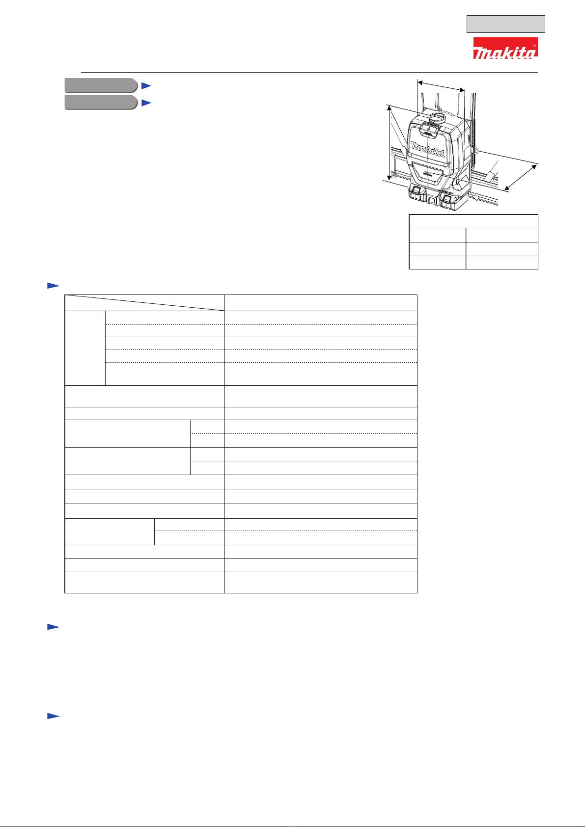
Model DVC260 is a cordless backpack vacuum cleaner powered by
two 18V Li-ion batteries in series.
The main features and benefits are:
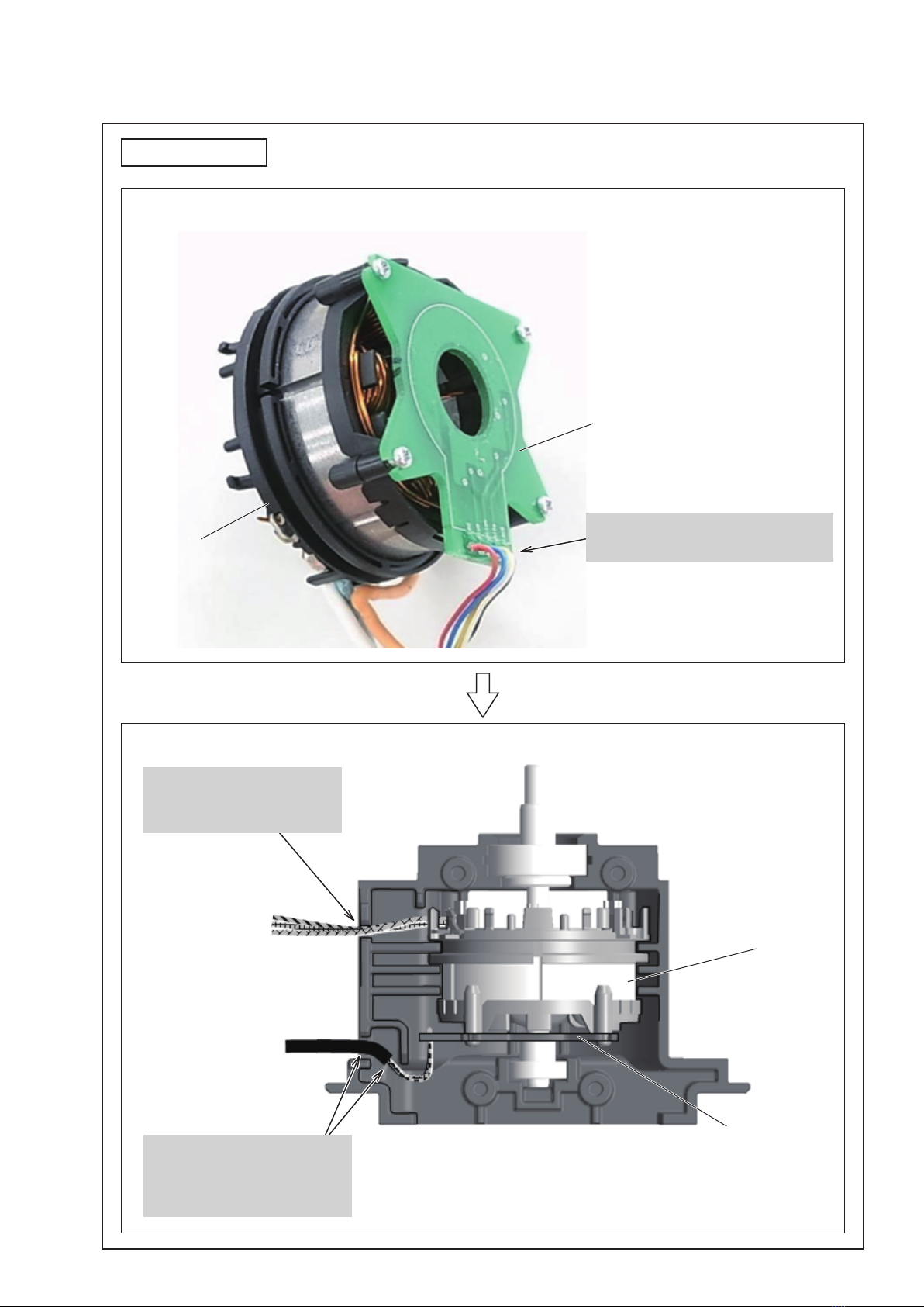
• Long run time thanks to energy-efficient brushless DC motor
• Controller operable in hand for on/off switching and
high/low power selection, with LED job light for job in the dark
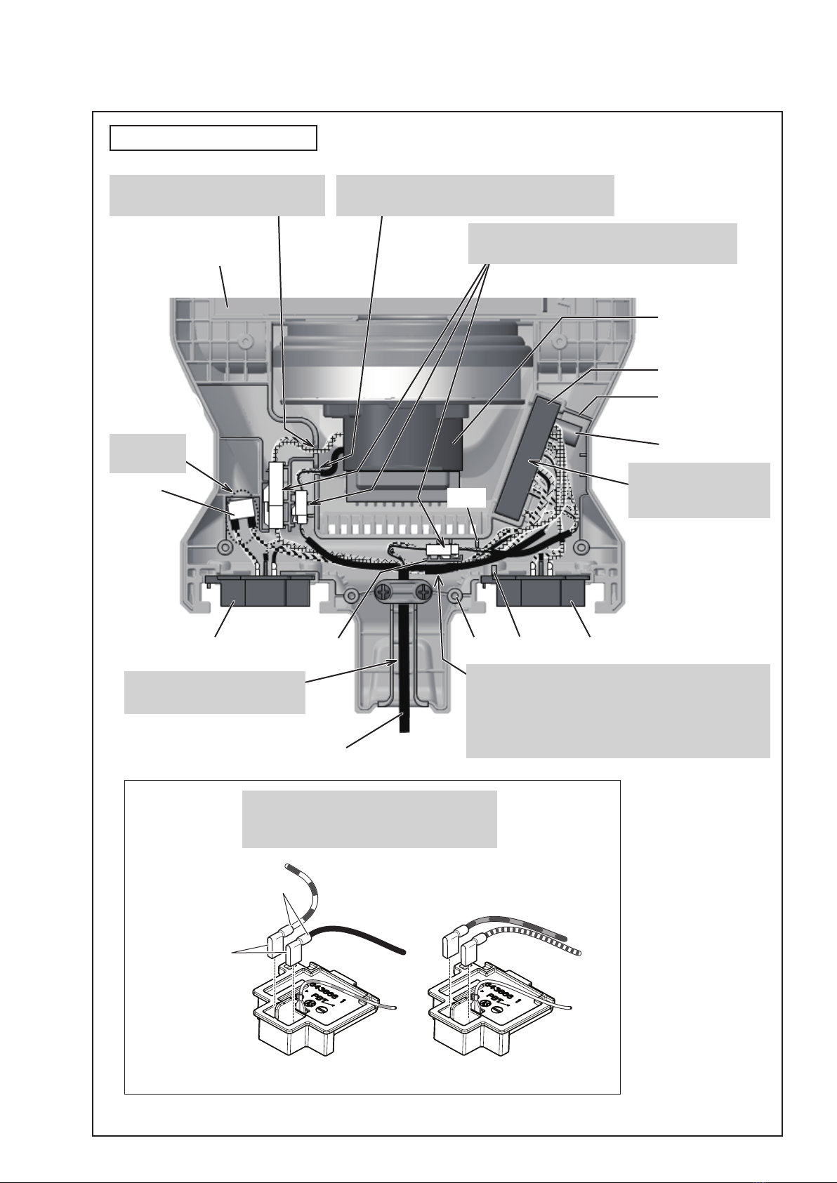
• Equipped with HEPA filter.
• Telescopic straight pipe adjustable to user’s height or various applications
• Flexible rubber nozzle, ideal for cleaning corners of stairs,
is supplied as standard.
• Reusable cloth dust bag is available as option.
Note: This model is not compatible with BL1815 (1.3Ah).
Dimensions*1: mm (")
Width (W)
Height (H)
Length (L)
152 (6)
230 (9)
373 (14-3/4)
Battery*4
Battery cover*5
Charger*4
Hose complete 28-1.0
Bent pipe assembly
Hose band
Filter bag (Paper dust bag)Nozzle assembly (Floor nozzle)
Flexible rubber nozzle
Telescopic pipe assembly
*4 Battery and charger are not supplied with “Z” model.
*5 Supplied with the same quantity of extra Battery.
Note: The standard equipment may vary by country or model variation.
W
L
H
Battery
Specification Model
Energy capacity: Wh
Voltage: V
Capacity: Ah
Cell Li-ion
Charging time (approx.): min 15x2, 24x2, 22x2, 36x2, 45x2, 55x2
with DC18RC
36 (18x2)
DVC260
Yes
Max air volume: m3/min
NoBattery capacity warning function
Yes
(High/Low)
Power selection
BrushlessDC motor
LED job light
Weight according to
EPTA-Procedure 01/ver.2.1: kg (lbs) 3.9 (8.7)*2, 4.3 (9.4)*3
2.0
1.5
Paper dust bag
Cloth dust bag
Dust bag capacity: L
60
90
Continuous run time (approx)
on a single full battery*1: min
1.5
Hose (standard equipment) ø28mm x 1m
1.5, 2.0, 3.0, 4.0, 5.0, 6.0
27x2, 36x2, 54x2, 72x2, 90x2, 108x2
*1 With BL1850x2 *2 With a Paper dust bag and 2 pcs of BL1815N or BL1820(B)
*3 With a Paper dust bag and 2 pcs of BL1830(B), BL1840(B), BL1850(B) or BL1860B
Suction power: W
7.1 (710)
45
25
Max sealed suction: kPa (mmH2O)
High
Low
High
Low
*1 Without Harness
March 2016
TECHNICAL INFORMATION
1 / 11
OFFICIAL USE
for ASC & Sales Shop

2 / 11
Repair
CAUTION: Repair the machine in accordance with “Instruction manual” or “Safety instructions”.
1 NECESSARY REPAIRING TOOLS
2 DISASSEMBLY/ASSEMBLY
Code No. Description Use for
1R402-A
-
-
-
Digital tester checking Controller
No.1 Phillips screwdriver press-fitting Ball bearing 6000DDW
No.2 Phillips screwdriver press-fitting Ball bearing 6901DDW/6001DDW
Slotted bit 10
Slotted screwdriver removing Ball bearing 6803ZZ
- removing Carrier complete
Index
1 NECESSARY REPAIRING TOOLS P 2
2-1. Removing Harness P 2
2-2. Replacing Motor and Fan 94 P 2-7
2-3. Disassembling/Assembling of Upper Housing P 8-12
2-4. Replacing/Cleaning of Rear Block Filter P 13-14
Circuit Diagram P 25
Wiring Diagram P 26-30
3TROUBLESHOOTING P 31-33
[2]-2. Replacing Motor and Fan 94
Fig. 2-2-1 Fig. 2-2-2
2-1. Removing Harness
Fig. 2-1-1 Fig. 2-1-2
(1) Pull up Back pad of Harness and
remove six M5 + Flat head screws.
The other three screws
are on the opposite side.
(2) Remove Harness.
(1) Remove Harness as shown in [2]-1.
(2) Remove Lower housing complete by unscrewing
eight 4x18 Tapping screws as shown below.
(3) Lift up and take Motor section out of Upper housing
complete.
Lower housing complete 4x18 Tapping screw
(8 pcs) Motor section
Upper housing complete
(4) Separate Motor section from Upper housing
complete by disconnecting two Connectors.
Connectors

3 / 11
Fig. 2-2-3 Fig. 2-2-4
(5) Disassemble Motor section as shown below. (6) Holding Fan 94 with leather safety gloves on,
remove M6 Hex nut by turning it counterclockwise
with an impact driver and Socket bit 10.
Fig. 2-2-5 Fig. 2-2-6
Fig. 2-2-7 Fig. 2-2-8
(7) Remove Fan 94 from Motor section as shown below.
Note:
The orientation ofFlange matters.
(11) Stand Motor on the rear end of Rotor
on a workbench, then push down Stator
to the workbench and then pull up Rotor
while pressing down Stator.
(12) Remove Controller B by unscrewing
four 2x10 + Pan head tapping screws.
Fig. 2-2-9
Assemble by reversing the disassembly procedure.
Note 1.
The recommended tightening torque for
four 2x10 + Pan head
tapping screws is 0.15-0.35 N·m (Fig. 2-2-8)
.
Note 2.
Remember that the orientation of Flange matters
(Fig. 2-2-5)
.
Note 3.
When tightening M6 Hex nut to fasten Fan 94 to Motor section:
• Hold Fan 94 as shown on right, with leather safety gloves on,
to prevent corotation of Fan 94 and M6 Hex nut.
• Turn M6 Hex nut clockwise with an impact driver and
Socket bit 10; if you use a DTD137 class impact driver,
set it in soft mode, then turn the nut for 0.5 minutes.
The recommended torque is 2-3 N·m.
Assembling
Support ring Fan cover Fan 94
Motor section
Washer 6
Be sure to hold Fan 94 to prevent
corotation of Fan 94 and M6 Hex nut.
M6 Hex nut
Impact driver
M6 Hex nut
Fan 94
Flange
(8) Remove
Support A.
(9) Remove Fan base
by unscrewing three
4x18 Tapping screws.
(10) Remove Motor housing L by
unscrewing four 4x18 Tapping screws.
Rotor
Stator
StatorSupportController B
No.1 Phillips
screwdriver 2x10 + Pan head tapping screw (4 pcs)

Fig. 2-2-10
Fig. 2-2-11
Magnetic loss
Surface damage
Inner cracks
StatorRotor
Printed wiring board
of Controller B
A correctly assembled
Motor section
will fit in Housing R snugly.
Note 4. When handling or storing multiple Rotors,
be sure to keep a proper distance between Rotors.
Because Rotor is a strong magnet, failure to follow
this instruction could result in:
• Finger injury from being pinched between Rotors
•Magnetic loss of Rotors or damage to Rotors.
Note 5. When inserting Rotor into Stator:
・While pushing Stator against a workbench, insert Rotor straight into Stator.
・Do not pinch your finger between Rotor and Stator.
・Once Rotor has been inserted, do not force
it into Stator any further or you will break
the printed wiring board of Controller B.
[2]-3. Disassembling/Assembling of Upper Housing
Fig. 2-3-1
4 / 11
Remove Seal from Dust box cover to replace it.
When assembling, match the shape of Seal with that
of the rib and then fit Seal over the rib, ensuring that
it is correctly located along its entire circumference.
Dust box cover
Seal
Replacement of Seal
Fig. 2-3-2
Remove Latch assembly by pushing it from the back of
Dust box cover. When assembling, fit Latch assembly in the
notches of Dust box cover and then push it from the front of
Dust box cover.
Open Dust box cover, then enlarge the hinge portion
from the inside with a slotted screwdriver and then
push Dust box cover Latch assembly to remove it
from Upper housing complete.
Set Dust box cover in the position where it was when
you had just removed it and then push it onto Upper
housing complete.
Replacement of Latch Assembly
Fig. 2-3-3
Removing Dust Box Cover
Fig. 2-3-4
Installing Dust Box Cover
Dust box cover
Latch assembly
Dust box cover
Upper housing complete
Slotted screwdriver
Dust box cover
Upper housing complete

Fig. 2-4-1
Note. Even if this vacuum cleaner is used with care and according to the instructions in the user’s manual,
dust may accumulate in Rear block filters, reducing the capacity of this vacuum cleaner.
So whenever Upper and Lower housing completes are separated, remove two Rear block filters
(one on each side) from Upper and Lower housing completes, and then:
• Remove dust from the inside of Upper and Lower housing completes by blowing with compressed air.
•Remove dust from Rear block filters by blowing with compressed air or washing with water.
[2]-4. Replacing/Cleaning of Rear Block Filter
5 / 11
Upper housing complete Lower housing complete
Rear block filter Rear block filter
Disassembling
(1) Follow the procedures described in 2-1 and 2-2 to remove Upper housing complete.
(2) Remove two Rear block filters (one on each side) from Upper and Lower housing completes,
and then remove dust from Rear block filters and Upper and Lower housing completes
as described in above Note.

Fig. D-1
Circuit Diagram
6 / 11
Black
White
Red
Orange
Blue
Yellow
Green
Color index of lead wires' sheath
Brown
Switch of Sub controller
(a) Off switch
(b) On/Speed control switch
(c) Switch for LED
(A) Connector
(B) Flag receptacle with lock
(#250, t=0.8mm)
(C) Straight receptacle with lock
(#187, t=0.8mm)
26AWG
26AWG
25AWG
Controller B Stator
Sub controller
LED
Controller A
Fuse
16AWG
22AWG
16AWG
16AWG
22AWG
16AWG 16AWG
Terminal A
Terminal B
26AWG
28AWG
16AWG
16AWG
26AWG
(a) (b) (c)
(A)
(A)
Strain
relief
Strain
relief
Power supply cord unit
(A)
(A)
(A)
(A)
(A)
(A)

In Motor Housing
Fig. D-2
Wiring Diagram
7 / 11
Stator
Controller B
Route three Lead wires
(orange, white, blue) of Stator
through this groove.
Route five Lead wires
(red, blue, yellow, white, black)
of Controller B through these
grooves.
Fasten Controller B to Stator as shown below.
Stator
Controller B
The side where Wires are connected
must be on the opposite side of Stator.

Fig. D-3
Wiring Diagram
8 / 11
LED
Do not route any Lead wires
in the area enclosed by the
white line.
Assemble Cord guard of
Power supply cord unit to
Switch case.
Do not assemble it to
Upper housing complete.
Power supply cord unit
In Switch Case
Sub controller Upper switch case
Put Connectors in this place as shown below.
Do not route any Lead wires over Connectors.
Fix two Lead wires (black, white)
of LED in these Lead wire holders.

Fig. D-4
Wiring Diagram
9 / 11
In Upper and Lower Housing
Terminal A Terminal BBoss
Fuse
Put Fuse in
this space.
Upper housing complete
Motor assembly
(Stator, Rotor,
Controller B)
Controller A
Rib A
Capacitor
Rib CRib D
Rib B
Power supply cord unit
Put Controller A in this
space with Capacitor
on Rib A side.
Put Connectors in place as shown below.
Do not route any Lead wires over Connectors.
Route Power supply cord unit
through this groove.
Route the following Lead wires of Controller A
between Ribs B and C and between Rib D and Boss:
• (black, yellow, red) to Terminal A
• (red, blue, yellow, white, black) to Controller B
• (orange, white, blue) to Stator
Fix Lead wires (orange, white, blue)
from Stator in this Lead wire holder.
Fix Lead wires (red, blue, yellow, white, black)
from Controller B in this Lead wire holder.
The Flag connector must be so connected
that its wire connecting portion is located
over the mark of + - poles.
Wire connecting portion
Flag connector
Terminal A Terminal B

10 / 11
Note in Repairing
Whenever you find any trouble in your machine, first, refer to this list to check the machine for solution.
(1) Use a full charged battery that has the star mark. (Fig. T-1)
(2) When Housing is disassembled, check the conditions of the electrical parts
(Connectors, Lead wires, Switches, etc.), Rotor, Stator, Gear section, etc.
(3) Do the running test 10 times.
3TROUBLESHOOTING
Fig. T-2
Troubleshooting of Controller Using Tester
Trouble on Controller can be checked with Tester (1R402-A) as described in Fig. T-2.
Fig. T-1
Star mark
(1) Set Tester (1R402-A) to Diode mode ( ). (2) Remove Battery from the machine,
(3) Touch (+) Terminal with the black probe and (-) Terminal
with the red probe. Then wait until the reading voltage
reaches a stable value.
Note: You cannot make a correct test, if you touch
(+) Terminal with the red probe and (-) Terminal
with the black probe.
Black probe
Red probe
(+) Terminal
(-) Terminal
(4) If it reads 0.9 V-1.3 V, Controller is in order.
If it reads 0 V, about 0.4 V or about 0.8V,
FET (Field Effect Transistor) built in Controller
is broken, and Controller must be replaced.

Check the connection.
11 / 11
[Flow Chart for Troubleshooting]
Check the items from top of the following list.
(Description of the item is referred to Circuit diagram in Fig. D-1.
After taking corrective action, be sure to re-check by following the chart from the start again.
Replace Controller A.
Probable Cause Corrective
Action
How to follow arrows:
No
Yes
Symptom
It reads 0.9V-1.3V on Tester.
(• See the previous page for how to
check Controller using Tester.
• Proceed to Yes if Tester is not
available.)
Disconnection of Lead wires Check the Lead wires,
or replace the Lead wires.
Check the Lead wires,
or replace the Lead wires.
Controller A is broken. Replace Controller A.
Sub controller is broken. Replace Sub controller.
LED lights up.
(Check whether LED lights up
by operating Switch for LED.)
Replace Controller A.Controller A is broken.
Replace Controller B.
Replace Sub controller.Sub controller is broken.
Controller B is broken.
Disconnection of Lead wires
Loose connection of
Connectors Check the connection.
Scratches on
Rotor core
Replace Rotor.
Replace Stator.Stator is broken.
Rotor is broken.
Check the Lead wires,
or replace the Lead wires.
Loose connection of
Connectors Check the connection.
Disconnection of Lead wires
Motor can be
stopped.
The machine
does not have
any trouble.
Controller A is broken.
Loose connection of
Connectors
Replace the broken one(s).
Either Terminal A or B
or both is broken.
Motor rotates.
(If you get
occasional success
in switching-on
out of 10 trials,
proceed to No.)
Replace Controller A.Controller A is broken.
Replace Sub controller.Sub controller is broken.
Replace Controller A.
The machine shows the same symptom
in spite of the corrective actions shown
above.
Other manuals for DVC260
13
Table of contents
Other Makita Vacuum Cleaner manuals

Makita
Makita DVC260 User manual

Makita
Makita DRC300 User manual

Makita
Makita DCL501Z User manual

Makita
Makita 447 M User manual

Makita
Makita VC011G User manual

Makita
Makita XLC05 User manual

Makita
Makita VC001GL User manual

Makita
Makita XCV17 User manual

Makita
Makita DVC265 User manual

Makita
Makita CL001G User manual

Makita
Makita BCL142 User manual

Makita
Makita GCV02 User manual

Makita
Makita DCL182Z User manual

Makita
Makita CL072DZ User manual

Makita
Makita VC001GL User manual

Makita
Makita VC011G User manual

Makita
Makita VC2211M User manual

Makita
Makita DRC200PT User manual

Makita
Makita VC1310L User manual

Makita
Makita EM4350RH User manual