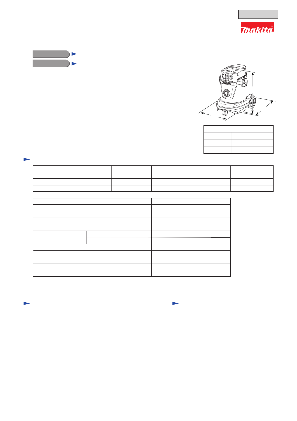
[1] NECESSARY REPAIRING TOOLS
DescriptionCode No. Use for
[2] LUBRICANT/ADHESIVE APPLICATION
Pipe ring (for arbor press)1R023
removing Caster 75Bearing extractor1R263
press-fitting Caster 75Type 94 field insert jig1R275
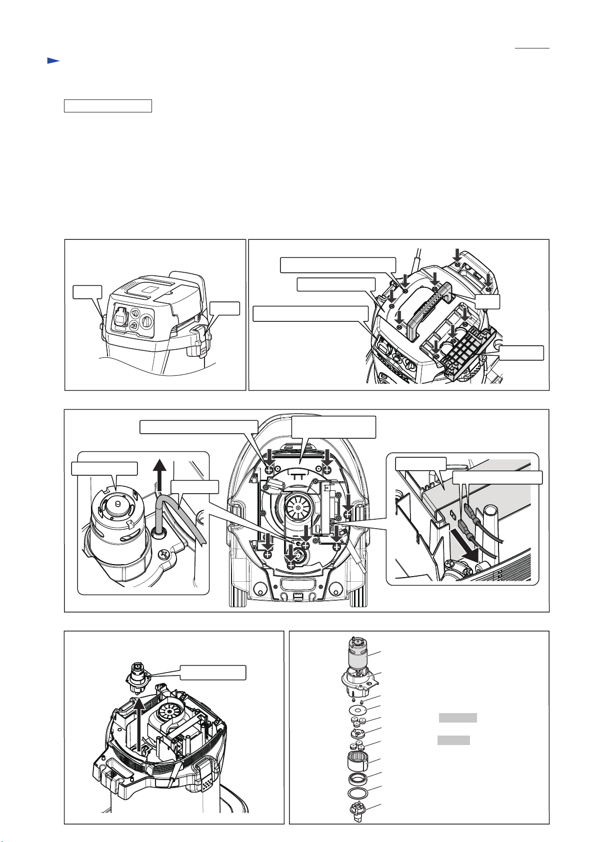
CAUTION: Repair the machine in accordance with “Instruction manual” or “Safety instructions”.
CAUTION: When performing startup test of the AC motor with the motor section separated from
the Tank section, be sure to hold the Motor section firmly, or it will move around.
CAUTION: When cleaning dust filtration parts or removing dust from other contaminated parts,
be sure to use Acrylic dust box (Code No. 1R276) so as not to scatter dust.
press-fitting Fan cover onto Return vane
removing dust from the machineAcrylic dust box1R276
V-block1R258 press-fitting Fan cover onto Return vane
Repair
Retaining ring S and R pliers1R291 removing/installing Retaining rings
Torque driver1R344 tightening M5x60 Pan head screws through Endbell and Field into Base
P 2/ 21
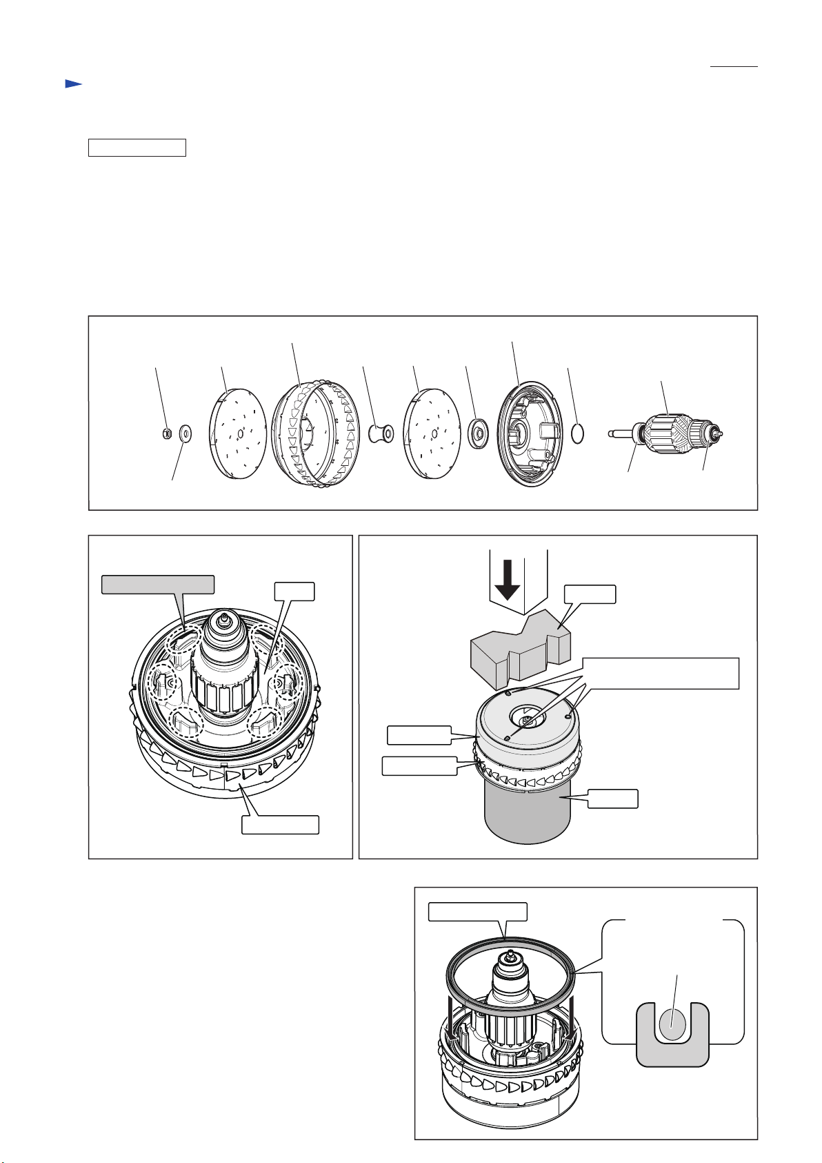
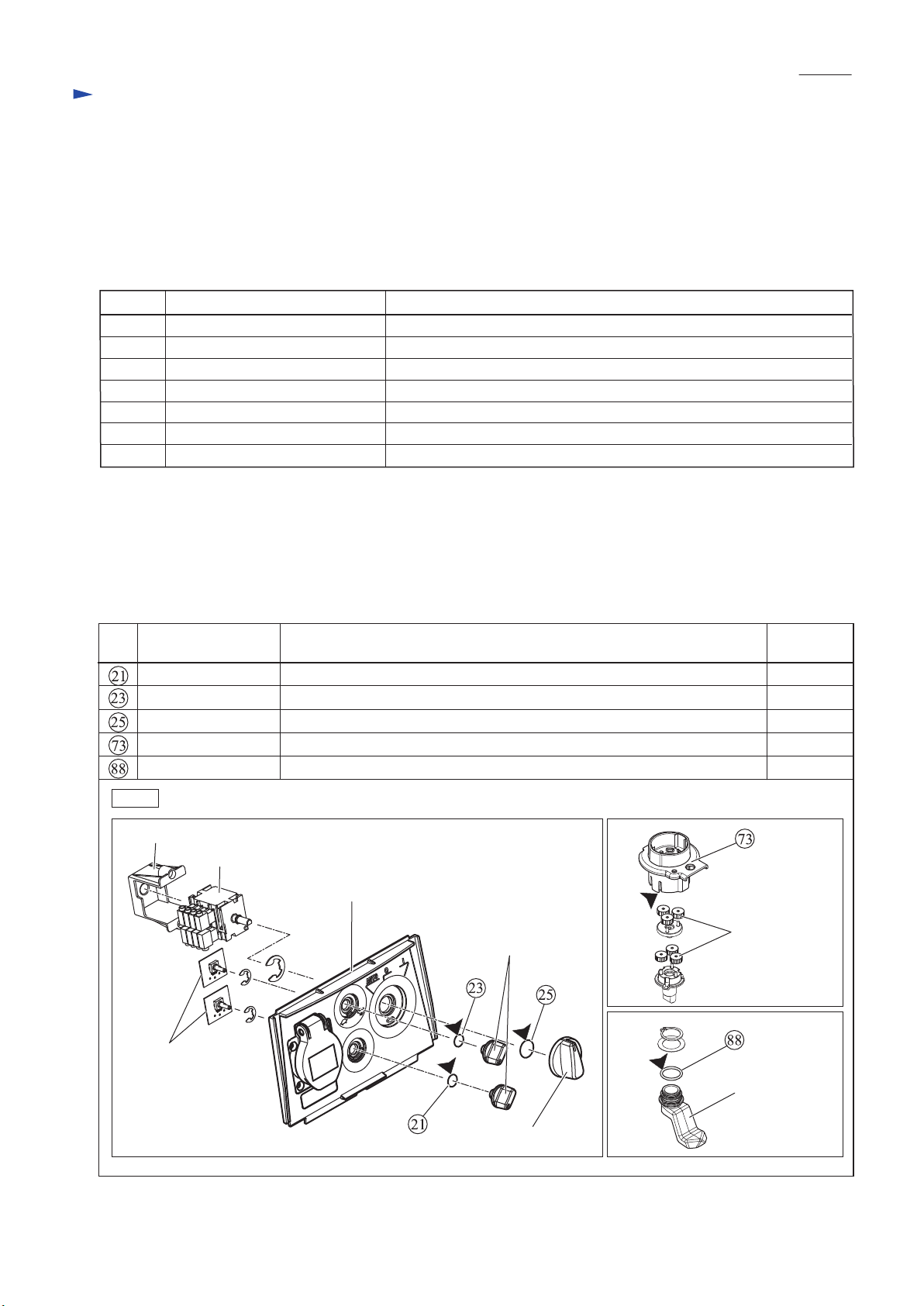
Fig. 1
Item
No. Description
O ring 9 whole surface
whole surface
O ring 14
a little
approx. 3g
whole surface
whole surface
Gear case gear chamber where planetary gears engage with Internal gear 42
O ring 9
a little
a little
a little
AmountPortion to lubricate
Apply Makita grease FA No.2 to the following portions designated by black triangle to protect parts and product from
unusual abrasion.. (Fig.1)
Apply ThreeBond 1215 to Rubber ring 120 and Seal ring.
See step (3) of "ASSEMBLING" in [3]-1. Motor section for Rubber ring 120,
and "ASSEMBLING" in [3]-2. Inner cover for Seal ring.
Cam
O ring 20
planetary gear
(Spur gear 15)
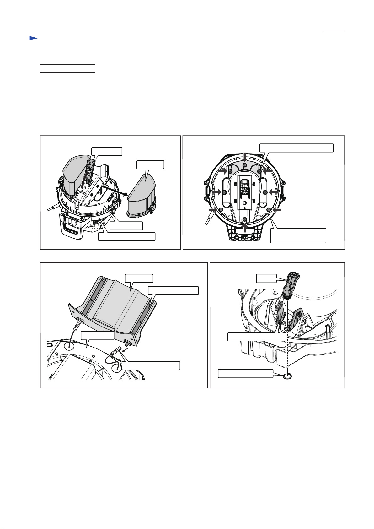
Switch
Switch holder
Sub controller
Switch base E-M complete
Switch lever
Switch dial