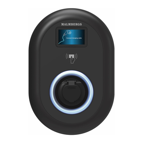
Malmbergs Evon User manual

Modell / Malli / Model: xxxxx 27 006 31, 77-79
EVON DUAL
WiFi/Bluetooth/4G
NOTE! Please read through the manual carefully before using the appliance and
keep it for future reference.
EN

2
1 ABOUT THIS MANUAL 3
1.1 Function of this manual 3
1.2 Disclaimer 3
1.3 Abbreviations 3
2 SAFETY AND WARNINGS 4
3 PRODUCT OVERVIEW 5-6
4 TECHNICAL SPECIFICATIONS 7
5 INSTALLATION 8-11
5.1 Check upon delivery 8
5.2 Install the back plate 9
5.3 Connect power cable 9
5.4 Connect network cable and insert SIM card 10
5.5 Plug the core box into the back plate 11
6 CONFIGURE NETWORK 11-13
7 CONDUCT A FUNCTION TEST 13
8 CONNECT THE CHARGING STATION TO EVCHARGO CLOUD 14
9 USE EVCHARGO APP TO CHARGE ELECTRIC VEHICLE 14
10 TROUBLESHOOTING 15
EN
WiFi Charging Station for Electric Vehicles
Content

3
1 ABOUT THIS MANUAL
1.1 Function of this manual
This document is only applicable for this Evon dual series charging station.
The document gives the information that is necessary to safely do these tasks:
• Install the charging station
• Use the charging station
• Do basic maintenance tasks
1.2 Disclaimer
Malmbergs shall not be liable for any damages, losses, costs or expenses resulting from the improper
handling of the charging station, in particular resulting from noncompliance with the instructions of
this document and other applicable regulations and standards (e.g. installation, transport, occupa-
tional health and other safety standards).
1.3 Abbreviations
Abbreviation Denition
AC Alternating current
EMC Electromagnetic compatibility
EV Electric vehicle
OCPP Open charge point protocol
PE Protective earth
RFID Radio-frequency identication
LBC Load Balance Controller
RCBO Residual current circuit breaker

4
2 SAFETY AND WARNINGS
Caution
• Failure to follow instructions may result in danger.
• Children are prohibited from touching the charging station.
• Do not disassemble the charging station while connected to the mains.
• Install the charging station away from pyrotechnics, dusty or corrosive places.
• Only use the charging station when it is operating normally and please strictly follow the instruc-
tions.
• The charging station produces high voltage output. You must pay attention to personal safety
when using it.
• If malfunction happens, it may cause electric shock or even death. Under emergency situations –
cut off the power supply.
Maintenance/Installation
• Maintenance and installation must be performed by a qualied electrician.
• The product is carefully packed in the factory. During transportation, strong impact and bumps
should be avoided to prevent damage to the outer packaging of the product.
• The product should be installed in an environment with an ambient temperature of
-30ºC – +50ºC and with a relative humidity of no more than 95%. The air should not contain
acids, alkalis or other corrosive or explosive gases.
Security Warning
Failure to follow instructions may result in danger!
• Regularly check whether the charging station has visible damage. There may be an electric shock
hazard when operating a broken charging station.
• If a ground fault occurs, it must be assumed that the cable carries voltage. Please conrm that
there’s no high-voltage power in the system before inspecting the charging.
• Persons who install and use charging stations must obey the principles and regulations mentioned
to ensure the personal safety and equipment safety.
• Before powering on the device, please conrm that the device is properly grounded to avoid un-
necessary accidents.
• Under any circumstances, do not open, modify or install the device yourself.
• To ensure the service life and stable operation of the charging station, the operating environment
should be kept as clean as possible with a relatively stable temperature and humidity. The charg-
ing station must not be used in ammable environment or environments with volatile gas.
• Please conrm that the input voltage, frequency, circuit breakers and other conditions of the
device meet the specications before the device is powered on.
• The device will stop charging automatically for safety, whenever a leakage current is detected.
You can start another charging session after the RCBO is reset.
• The charging station is equipped with a RCBO 40A 30mA+6mA DC leakage current detection.
• Test of RCBO: Press test button on the RCBO.
5
3 PRODUCT OVERVIEW
External overview of the wall box
1. Front cover
2. Charging socket
3. Back plate
4. Circuit breaker
5. Energy meter
6. Network cable inlet
7. Power cable inlet/outlet
(bottom side)
8. Power cable inlet/outlet
(top side)
9. Power cable inlet/outlet
(rear side)
1
3
9
2
4 4
5
6
8
7
5

6
Internal overview of the wall box
1. RCBO
2. Smart meter
3. RS 485 port
4. Cable entry
5. Cooling fan
6. Terminals
7. Ethernet port
8. SIM card
9. Socket
10. Socket details
11. RCBO details*
12. RS485 port, SIM, Ethernet port details
4
1
9
5
1
10 12
1
6
2
7
8
11
2
3
Note: press the “Reset” button for 5s, and you can reset the PIN code in the AP mode
network conguration.

7
4 TECHNICAL SPECIFICATIONS
A Circuit Breaker (MCB) installed at source is recommended.
Art.no. 27 006 31, 77-79
Input
Power Supply 3P+N+PE
Rated Voltage 400V AC
Rated Current 32A
Frequency 50/60Hz
Output
Output Voltage 400V AC
Maximum Current 32A
Output Power 2x11kW/1x22kW
User Interface
Connector Type 2xType 2 Socket
Enclosure PC
LED Indicator Green/Yellow/Red
RFID Reader Mifare ISO/IEC 14443A
Start Mode Plug&Charge/RFID Card/App
Communi-
cation
WiFi Yes
4G Yes
Ethernet Yes
Bluetooth Bluetooth Low Energy (BLE 4.1) 2402-2480 MHz
(for installer conguration purposes)
OCPP OCPP1.6 Json(OCPP2.0 Upgradable)
Safety
RCBO 40A Type A
RCD 30mA AC+6mA DC
Ingress Protection IP54
Impact Protection IK08
Electrical Protection
Over current protection, Residual current protection,
Short circuit protection, Surge protection, Over/Under
voltage protection, Over/Under frequency protection,
Over temperature protection
Certication CE/RoHS/Reach
Certication Standard EN IEC 61851-1:2019, EN IEC 61851-21:2021,
IEC 62955:2018, IEC 62321
Grounding system
support TT, TN, IT
Environment
Installation Wall-/Floor mounting (Optional)
Working Temperature - 30°C - +50°C
Working Humidity 5%~95%
Work Altitude <2000 m
Package
Product Dims (WxHxD) 369x559x197 mm
Package Dims (WxHxD) 466x620x245 mm
Net Weight 10 kg
Gross Weight 12 kg
Terminal Specication 100A (Max.) 25 mm²
Measurement Meter MID (27 006 77/79)

8
5 INSTALLATION
5.1 Check upon delivery
Check the box upon receiving the charging station to ensure you have the following parts:
If you are missing any of these parts, please contact us.
Cord end terminal
(x10)
Cable clip
(x2)
Anchor bolt
(x4)
M6x16 screw
(x4)
L-shaped wrench
(x1)
Gland
(x1)
Charging station
(x1)
Cable rubber cover
(x2)
RS485 cable terminals
(x2)
Installation diagram
(x1)
EMC Standard (EMC)
EN IEC 61851-21-2: 2021
Safety Standard (LVD)
EN IEC 61851-1:2019
RoHS Standard (RoHS)
IEC 62321-2:2021, IEC 62321-1:2013,
IEC 62321-3-1:2013, IEC 62321-4:2013+A1:2017,
IEC 62321-5:2013, IEC 62321-7-1:2015,
IEC 62321-7-2:2017, ISO 17075-1:2017,
IEC 62321-6:2015, IEC 62321-8:2017
RF & Health
EN 300 328 V2.2.2:2019, EN 300 330 V2.1.1:2017,
EN 301 489-1 V2.2.3:2019, EN 301 489-3 V2.1.1:
2019, EN 301 489-17 V3.2.0:2017, EN 62311:2020
REACH
1907/2006, REACH etc. (Amendment) Regulations
2021
AC cable requirement
Cable with a cross-sectional area of 16~25 square
millimetres meeting VDE is highly recommended,
with temperature resistance above 105°C.
DECLARATION OF CONFORMITY
We hereby certify that the device satises the provisions
for CE marking in accordance with the EU directives (LV
Directive 2014/35/EU, EMC Directive 2014/30/EU, RE
Directive 2014/53/EU, RoHS Directive 2011/65/EU,
(EU) 2015/863) as described in this manual.
For and on behalf of:
Malmbergs Elektriska AB, Sweden.
Mr. Anders Folke / Product Manager
Date: 26/12/2023

9
5.2 Install the back plate
Installation Diagram
5.3 Connect power cable
a
b
c
Diameter: 4xØ8 mm
Depth: ≥40 mm
Wall/Solid board
d
4-M6x40
Ø 22-28 mm Ø 15-21 mm
TT/TN IT Single-phase IT
Based on the cabling
positions
12 mm
e
For three-phase IT wiring, in addition
to the regular wring, the L2 and N lines
should be short-circuited.
4x
Ø7
320 mm
170 mm
170 mm
480 mm
258 mm

10
Method 2: Parallel Connection
5.4 Connect network cable and insert SIM card
RS485
ports
RJ45
ports
SIM card
slot
Ethernet cable:
Connect the cable to the RJ45 connector then
plug the connector into the port.
SIM card:
Push the cover down and ip it open, then put
the SIM card in the slot.
RS485 cable:
As shown below, clamp the wires then plug the
terminal into the port.
Method 1: Series Connection (Max. 100A)
SIM

11
5.5 Plug the core box into the back plate
Tighten the screws on the both sides of the wall-
box to secure it to the back plate rmly.
6 CONFIGURE NETWORK
Decide what internet connection should be used for the installation. There are three types of
internet connection that is possible to use for installation.
a). Ethernet cable from the router/switch.
b). Local WiFi connection from the building where the installation is set up.
c). Built-in 4G/LTE module, support insert 4G SIM card.
The charging station is equipped with a built-in WiFi module that contributes to an easy
installation. However, large distances or radio obstacles may require physical ethernet cable
connections.
WWW

12
AP Mode Introduction
If you select WiFi for communication, you must rst congure the internet for the charging station.
The following steps show the conguration with AP mode.
Private scenario: If you use the charging station in a private scenario, you can bind the charging
station to the Evchargo APP directly, please go to page 14 to check the Evchargo user manual to get
more information.
Public scenario: If you use the charging station in a public scenario, please remember to add the
charging station SN to the Evchargo platform via the backend account rst, and then check the AP
Mode Instruction below to congure the network.
Connecting to a third platform: If you want to connect the charging station to a third platform,
please refer to the AP Mode Instruction below, and enter the correct server address.
Step 1: Activate the charging station's hotspot
Activate the hotspot of the charging station by restarting the power supply.
Step 2: Establish a communication between the charging station and your phone
Switch your phone to ight mode, and make sure that the WLAN is enabled.
The charging station
will send out a hotspot
after it is restarted
WiFi name: the serial number
of the charging station
WiFi password: see below
Select the WiFi hotspot sent
out by the charging station and
enter the password to connect.
Charging station WiFi Phone
The hotspot of the charging station remains available for 15 minutes after the charging station
has been restarted.
An 8-digit password which can be found on the last page of the manual or on the RCBO
inside the charging station. The password is unique to the device and case sensitive.
The PIN number can be found on the RCBO and
on the last page of the user manual.
Step 3: Login
To access the LOGIN page of AP mode, enter the IP address
192.168.4.1 in a browser, followed by the 4-digit network
password (PIN number).

13
Step 4: Congure WiFi
After logging in, you will be prompted with the following interfaces:
7 CONDUCT A FUNCTION TEST
Use the vehicle simulation adapter or EV to conduct a functional test.
Choose WiFi as your charge
point's communication method.
Choose a WiFi hotspot.
Enter the WiFi password
wss://ocpp16.evchargo.
com:33033
Choose the grid type:
TN, TT or IT.
Click to complete the
Network conguration
Your charging station will automatically restart once the network conguration is complete,
ending communication between your phone and the charger, at this point, your phone may
automatically join to other WiFi hotspots, preventing you from accessing the network congu-
ration interface. As a result, before accessing the network conguration interface, please ensure
that your phone is connected to the charging station’s WiFi hotspot.

14
8 CONNECT THE CHARGING STATION TO EVCHARGO CLOUD
Evchargo Cloud is a software that serves business operators, and it addresses the demands for charg-
ing points, charge point monitoring and management, and intelligent and efcient operation and
maintenance.
To connect the charging station to the Evchargo Cloud, please scan the code below for instructions.
9 USE EVCHARGO APP TO CHARGE ELECTRIC VEHICLE
Evchargo is an app that allows EV drivers to locate public charging points to charge their electric
vehicles and bind the charge point to the Evchargo APP as a private charge point, please scan the
code below for instructions.

15
10 TROUBLESHOOTING
Problems LED Status
Warning (Ground fault,
tampering, etc.) Solid yellow light
Relay adhesion Solid red light
Leakage current fault The LED blinks red once and then goes out for 3s, cycling.
CP fault The LED blinks red twice and then goes out for 3s, cycling.
Over current fault The LED blinks red three times and then goes out for 3s, cycling.
Input polarity reverse The LED blinks red four times and then goes out for 3s, cycling.
Leakage current loop
abnormal The LED blinks red ve times and then goes out for 3s, cycling.
Input terminal
overtemperature The LED blinks red six times and then goes out for 3s, cycling.
Relay overtemperature The LED blinks red seven times and then goes out for 3s, cycling.
Over/Under voltage fault The LED keeps solid yellow for 2s, then blinks red once and
then goes out for 3s; cycling.
Over / Under
frequency fault
The LED keeps solid yellow for 2s, then blinks red twice and
then goes out for 3s; cycling.
Meter comm abnormal The LED keeps solid yellow for 2s, then blinks red three times
and then goes out for 3s; cycling.
Smart meter comm
abnormal
The LED keeps solid yellow for 2s, then blinks red four times
and then goes out for 3s; cycling.
CT fault The LED keeps solid yellow for 2s, then blinks red ve times
and then goes out for 3s; cycling.
Charging connector lock
abnormal
The LED keeps solid yellow for 2s, then blinks red six times and
then goes out for 3s; cycling.
Charging connector current
abnormal
The LED keeps solid yellow for 2s, then blinks red seven times
and then goes out for 3s; cycling.
PIN CODE

Malmbergs Elektriska AB, PO Box 144, SE-692 23 Kumla, SWEDEN
AF-JA/JZ-231226
Other manuals for Evon
1
This manual suits for next models
4
Table of contents
Other Malmbergs Batteries Charger manuals

Malmbergs
Malmbergs T513 User manual

Malmbergs
Malmbergs T511 User manual

Malmbergs
Malmbergs 24 800 16 User manual

Malmbergs
Malmbergs C0043 User manual

Malmbergs
Malmbergs EVC04 Series User manual

Malmbergs
Malmbergs PSD004 User manual

Malmbergs
Malmbergs PSD008 User manual

Malmbergs
Malmbergs Evon WiFi/4G User manual

Malmbergs
Malmbergs WiFi EVC User manual

Malmbergs
Malmbergs EVC04-AC22 Series User manual