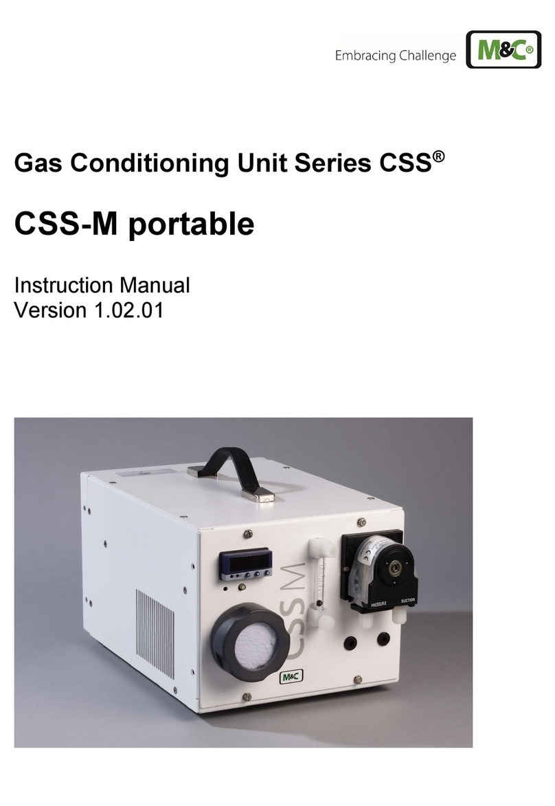
M&C PSS Series User manual

Portable Gas Conditioning Unit Series PSS®
PSS-10/1
Instruction Manual
Version 1.00.02

2 PSS-10 | 1.00.02 www.mc-techgroup.com
Dear customer,
Thank you for buying our product. In this manual you will find all necessary information about this M&C product.
The information in the manual is fast and easy to find, so you can start using your M&C product right after you
have read the manual.
If you have any question regarding the product or the application, please don’t hesitate to contact M&C or your
M&C authorized distributor. You will find all the addresses in the appendix of this instruction manual.
For additional information about our products, please go to M&C’s website www.mc-techgroup.com. There you
can find the data sheets and manuals of our products in German and English.
T
his instruction manual does not claim completeness and may be subject to
technical modifications.
© 10/2022 M&C TechGroup Germany GmbH. Reproduction of this document
or its content is not allowed without permission from M&C.
PSS®is a registered trade mark.
Version: 1.00.02

www.mc-techgroup.com PSS-10 | 1.00.02 3
Content
1General information........................................................................................................................................ 4
2Declaration of conformity.............................................................................................................................. 4
3Safety instructions........................................................................................................................................... 5
4Warranty ............................................................................................................................................................ 5
5Used terms and signal indications ............................................................................................................... 6
6Introduction...................................................................................................................................................... 8
7Application........................................................................................................................................................ 8
8Technical data .................................................................................................................................................. 9
9Description...................................................................................................................................................... 10
10 Receipt of goods and storage ..................................................................................................................... 12
11 Installation instructions................................................................................................................................ 13
12 Supply connections....................................................................................................................................... 14
12.1 Tube connections.........................................................................................................................................................................................14
12.2 Electrical connections ................................................................................................................................................................................16
13 Commisioning ................................................................................................................................................ 17
14 Closing down .................................................................................................................................................. 18
15 Maintenance ................................................................................................................................................... 19
16 Trouble shooting ........................................................................................................................................... 20
17 Proper disposal of the device...................................................................................................................... 21
18 Spare parts list................................................................................................................................................ 22
19 Appendix ......................................................................................................................................................... 23
List of Figures
Figure 1 Flow sheet.......................................................................................................................................................................................................8
Figure 2 Design of the portable conditioning and sampling system PSS-10/1...................................................................10
Figure 3 Medium connections............................................................................................................................................................................14
Figure 4 Connecting heated sample line with special adapter (option)..................................................................................24
Figure 5 Circuit diagram PSS-10/1, shown here: circuit diagram for 230 V.............................................................................25

4 PSS-10 | 1.00.02 www.mc-techgroup.com
HEAD OFFICE
M&C TechGroup Germany GmbH Rehhecke 79 40885 Ratingen Germany
Telephone: 02102 / 935 – 0
Fax: 02102 / 935 – 111
www.mc-techgroup.com
1GENERAL INFORMATION
The product described in this instruction manual has been built and tested in our production facility.
All M&C products are packed to be shipped safely. To ensure the safe operation and to maintain the safe
condition, all instructions and regulations stated in this instruction manual need to be followed. This instruction
manual includes all information regarding proper transportation, storage, installation, operation and maintenance
of this product by qualified personnel.
Follow all instructions and warnings closely.
Read this manual carefully before commissioning and operating the device. If you have any questions regarding
the product or the application, please don’t hesitate to contact M&C or your M&C authorized distributor.
2DECLARATION OF CONFORMITY
CE - Certification
The product described in this operating manual complies with the following EU directives:
EMV-Instruction
The requirements of the EU directive 2014/30/EU “Electromagnetic compatibility“ are met.
Low Voltage Directive
The requirement of the EU directive 2014/35/EU “Low Voltage Directive“ are met.
The compliance with this EU directive has been examined according to DIN EN 61010.
RoHS Directive
The requirements of the RoHS2 (‘Restriction of Hazardous Substances 2’) directive 2011/65/EU and its annexes are
met.
Declaration of conformity
The EU Declaration of conformity can be downloaded from the M&C homepage or directly requested from M&C.

www.mc-techgroup.com PSS-10 | 1.00.02 5
3SAFETY INSTRUCTIONS
Please take care of the following basic safety procedures when mounting, starting up or operating this
equipment:
Read this operating manual before starting up and use of the equipment. The information and warnings given in
this operating manual must be heeded.
Any work on electrical equipment is only to be carried out by trained specialists as per the regulations currently in
force.
Attention must be paid to the requirements of VDE 0100 (IEC 364) when setting high-power electrical units with
nominal voltages of up to 1000 V, together with the associated standards and stipulations.
Check the details on the type plate to ensure that the equipment is connected to the correct mains voltage.
Protection against touching dangerously high electrical voltages:
Before opening the equipment, it must be switched off and hold no voltages. This also applies to any external
control circuits that are connected.
The device is only to be used within the permitted range of temperatures and pressures.
Check that the location is weather-protected. It should not be subject to either sun, direct rain or moisture.
Do not use the gas conditioning system PSS-10/1 in hazardous areas.
Installation, maintenance, inspections and any repairs of the devices must be carried out only by qualified skilled
personnel in compliance with the current regulations.
4WARRANTY
In case of a device failure, please contact immediately M&C or your M&C authorized distributor.
We have a warranty period of 12 months from the delivery date. The warranty covers only appropriately used
products and does not cover the consumable parts. Please find the complete warranty conditions in our terms
and conditions.
The warranty includes a free-of-charge repair in our production facility or the free replacement of the device. If
you return a device to M&C, please be sure that it is properly packaged and shipped with protective packaging.
The repaired or replaced device will be shipped free of delivery charges to the point of use.

6 PSS-10 | 1.00.02 www.mc-techgroup.com
5USED TERMS AND SIGNAL INDICATIONS
DANGER!
This means that death, severe physical injuries and/or important material
damages will occur in case the respective safety measures are not fulfilled.
WARNING!
This means that death, severe physical injuries and/or important material
damages may occur in case the respective safety measures are not fulfilled.
CAUTION!
This means that minor physical injuries may occur in case the respective
safety measures are not fulfilled.
CAUTION! Without the warning triangle means that a material damage may occur in
case the respective safety measures are not met.
ATTENTION This means that an unintentional situation or an unintentional status may
occur in case the respective note is not respected.
NOTE!
These are important information about the product or parts of the
operating manual which require user’s attention.
SKILLED STAFF These are persons with necessary qualification who are familiar with
installation, use and maintenance of the product.
QUALIFIED PERSONNEL These are persons with necessary qualification who are familiar with
installation, use and maintenance of the product.
High voltages!
Protect yourself and others against damages which might be caused by
high voltages.
Corrosive!
These substances destroy living tissue and equipment upon contact.
Do not breathe vapors; avoid contact with skin and eyes.
Wear protective gloves!
Working with chemicals, sharp objects or extremely high temperatures
requires wearing protective gloves.

www.mc-techgroup.com PSS-10 | 1.00.02 7
Wear safety glasses!
Protect your eyes while working with chemicals or sharp objects. Wear
safety glasses to avoid getting something in your eyes.
Wear protective clothes!
Working with chemicals, sharp objects or extremely high temperatures
requires wearing protective clothes.

8 PSS-10 | 1.00.02 www.mc-techgroup.com
6INTRODUCTION
The portable gas conditioning and sampling system PSS-10/1 has been especially designed so that precise gas
analyses can be carried out in any place and at any time.
The entire gas conditioning system is housed in a compact and robust aluminium framed case which ensures
that the components can be removed easily, and gas analysis carried out quickly, safely and with a minimum
amount of maintenance.
7APPLICATION
The gas conditioning and sampling system is ideally suited for both intermittent and continuous operation.
The components of the system PSS-10/1 are intended for "standard use." We also provide a wide range of
additional equipment and other components should special measurements be required.
Figure 1 Flow sheet
Sample gas probe, material stainless steel 316, diameter 4/6 mm, length 0.5 m
Sample gas line, PVC hose DN 4/6 mm, length 3 m
Gas cooler ECP20/2
Fine filter FP-2T, filter element fineness 2 μm
Sample gas diaphragm pump N9KPE
Flowmeter FM40, option
Pre-filter PF 2
Peristaltic pump SR25.1 for continual removal of condensate
+5 °C [41 °F]
ECP 20-2
Sample gas
IN
Condensate OUT

www.mc-techgroup.com PSS-10 | 1.00.02 9
8TECHNICAL DATA
Gas conditioning unit Version PSS-10/1
Sample outlet dew point Range of adjustment: +2 to +15 °C [35.6 to 59 °F], factory setting: +5
°C [41 °F]
Dew point stability At const. conditions: < ±0.1°C [±0.18 °F]
Sample inlet temperature **Max. 80 °C [176 °F]
optional:
**max.180 °C [356 °F] with stainless steel bulkhead union
Sample inlet dew point **Max. +80 °C [176 °F]
Gas flow rate **Max. 480 Nl/h
Ambient temperature **+5 up to +40 °C [41 to 104 °F]
Storage temperature -25 up to +65 °C [-13 to +149 °F]
Pressure 0.7 bar up to 1.4 bar abs.
Total cooling capacity at 25 °C ambient
temperature
Max. 80 kJ/h
Number of gas inlets 1
Number of gas outlets 1
Optional: max. 4
Medium connections Tube connection 4/6 mm
Material of sample contacting parts Stainless steel, glass, PVDF, VITON, Novopren®
Ready for operation Approx. 10 min
Power supply 230 V 50 Hz ±10 % or 115 V 60 Hz ±10 %
Power consumption Max. 350 VA
Fuse protection 6.3 A slow-acting, 5 x 20 mm with option temperature controller:
10
A slow-acting
Electrical connection Cold appliance plug with 2 m [≈ 6.56 ft] of cable
Case protection IP20 (EN 60529)
Housing Portable aluminium framed case
Housing dimensions (H x W x D) 555 x 460 x 290 mm [≈ 21.9” x 18.1” x 11.4”]
Weight Approx. 24 kg [≈ 52.9 lbs]
Part No. for 230 V 50 Hz version
Part No. for 115 V 60 Hz version
01G5000
01G5000a
Options:
Flow meter DK800R mounted in
sample gas outlet:
Altern. 10-100 l/h (Part No.: 01G9020), 25-250 l/h (01G9021) and 50-50
l/h (01G9022) air
Temperature controller for heated line:
Liquid alarm type
Range of control: 0 – 200 °C 230 V, max. 4 A
input PT100 115 V, max. 4 A
LA 1S/LA-1.4
Electrical equipment standard EN 61010
PPH=Polypropylene, PTFE=Polytetrafluoroethylene (Teflon®), PVC=Polyvinyl chloride, PVDF=Polyvinylidenfluoride
* Standard
** Maximum values in technical datas must be rated in consideration of total cooling capacity at 25 °C ambient temperature and an outlet
dew point of 5 °C.

10 PSS-10 | 1.00.02 www.mc-techgroup.com
9DESCRIPTION
Powe
r
Sam
p
le
OUT
OUT
Condensate
IN
Sample
GL 18
GL 25
555
420290
4
6
5
7
8
3
3
2
1
Figure 2 Design of the portable conditioning and sampling system PSS-10/1
All the components of the gas conditioning system can be easily removed from the portable case. The door of
the case can be opened by moving the toggle-type fasteners on the side and the top to the left.
The installation of a gas cooler and an appropriate diaphragm gas pump will be carried out according to
the maximum flow of gas extracted (see instruction manual for individual components). The possible
combinations are listed in the following table:
The minimum amount of flow is determined by the sample gas pump. Premature damage can be caused to the
pump membrane if less than the minimal total amount of flow is extracted as a result of excess pressure.
All gas coolers are equipped with a Duran glass heat exchanger. Heat exchangers of PVDF or stainless steel are
also available.
The preliminary filter FP-2T (2 μm filter element fineness) installed in front of the gas measuring pump ensures
that the correct amount of solid matter is precipitated.
The sample gas pump is turned off and on automatically by means of an excess temperature contact on the
cooler (+8 °C).
The resulting condensation is continually lead off by means of the SR25.1 peristaltic pump (see Appendix for
individual component instructions).
A preliminary filter, PF2 has been fitted in the condensation hose in between the heat exchanger and peristaltic
pump. This prevents particles in the condensate entering the pump.
The 4/6 mm hose connections for the condensate and measuring leads are located on the right-hand side of
the case (see figure 2 and 3).
The stainless steel sample probe (0.5 m length, 6 mm diameter) and the 3 m sample line (DN 4/6 mm) are
delivered with all models.
The ventilation grids located in the lid and the left-hand side of the case ensure that the equipment is sufficiently
ventilated.

www.mc-techgroup.com PSS-10 | 1.00.02 11
Options
The gas conditioning and sampling system PSS-10/1 consists of standard one gas-measuring outlet terminal. An
additional flow meter (DK800R), with needle valve, can be fitted to this terminal, whereby the adjustment of the
terminals is carried out in accordance with the specified volume flow rate (see 3.).
In order to protect additionally connected analysers against fluid irruption, and increase the operational safety of
the entire system, we recommend that a fluid alarm sensor LA 1S be installed. In such a case, the preliminary
filter FP-2T, which is delivered with all models, will be replaced with the FP-2T-D preliminary filter by the
manufacturer (see appendix). The LA-1.4 electronics is located on the clamp mounting rail in the upper part of
the case. In the event of a fluid irruption, the LA electronics automatically turns off the sample gas pump. The
alarm will be raised by means of a red LED. If the equipment is functioning properly, i.e. no alarm, a green LED
will be on.
The PSS-10/1 can also be equipped with an additional gas measuring inlet terminal (see figure 3, part No.
01G9062 and 01G9063) in order to connect a heated sample line. The existing anti-kink device is only to be used
for heated sample lines in conjunction with the model "C" connection (part No. 03B1012). Mounting instructions
can be found in the Appendix.
The heated sample line, part No. 01B4035, can also be fitted in conjunction with the sample gas probe PSP
4000.
In the event that the heated line is ordered as additional equipment, the necessary temperature controller 701
(part No. 01G9055(a)) will be fitted to enclosure by the manufacturer.
A 3-way ball valve (01G9046) or 5-way ball valve (01G9045) can be fitted to the inlet terminal of the gas
conditioning system in order to calibrate analyser(s) with check gas, or to switch from one sample gas
measurement to another.

12 PSS-10 | 1.00.02 www.mc-techgroup.com
10 RECEIPT OF GOODS AND STORAGE
CAUTION!
Heavy device!
Risk of injury when handling heavy equipment.
Do not lift, move or carry the device without help. A second person is
required to lift, move or carry the device.
The portable gas conditioning and sampling system PSS-10/1 is a completely pre-fitted unit.
The sample gas probe, sample gas line, connection cable and instruction manual are located in the inside part of
the case door.
Please take the portable gas conditioning system and possible special accessories carefully out of the
packaging material immediately after arrival, and compare the goods with the items listed on the delivery
note.
Check the goods for any damage caused during delivery and, if necessary, notify your transport insurance
company without delay of any damage discovered.
NOTE!
The PSS must be stored in a weather-protected frost-free area!

www.mc-techgroup.com PSS-10 | 1.00.02 13
11 INSTALLATION INSTRUCTIONS
CAUTION!
Heavy device!
Risk of injury when handling heavy equipment.
Do not lift, move or carry the device without help. A second person is
required to lift, move or carry the device.
NOTE!
When in use, the gas conditioning system case should be placed in an area well
away from any heat emitting sources in order to prevent damage caused by an
accumulation of heat. The air vents in the case must be free at all times.
In order to ensure that the case is safe and stable when being used, it should be
laced on a horizontal surface.
The equipment is to be used in a vertical position only. The perfect functioning of
the separation and drainage procedures will only be guaranteed if the equipment is
used in a vertical position.
When the equipment is being used outside, ample protection against the effects of
direct sunlight and dampness must be provided. In winter, the equipment must
only be used in frost-free areas.
It is recommended that the case be protected using one of the many models
available.
In order to guarantee the operational safety of the gas conditioning system and the
additionally connected analysers, and to avoid false alarms, the gas conditioning
system should not be used at temperatures other than those specified.
It is of great importance that the analysers which have been additionally connected
be used at temperatures well above the specified gas outlet dew point of +5 °C [41
°F]. This prevents the gas in the connector lines from condensing completely.
In the event of the unheated sample gas lines being connected to the gas
conditioning system on a slope, it is not necessary to carry out a preliminary
condensate removal.

14 PSS-10 | 1.00.02 www.mc-techgroup.com
12 SUPPLY CONNECTIONS
12.1 TUBE CONNECTIONS
NOTE!
Do not switch tube connections; connections are marked accordingly.
After all lines have been connected, the tightness must be checked.
Figure 3 shows the possible medium connections. These are located in the right-hand side of the gas
conditioning case at the rear in a specially immersed assembly frame.
Power
supply
Sam
p
le
g
as
OUT
OUT
Condensate
IN
Sample gas
Figure 3 Medium connections
All hose connections are equipped with 4/6 mm sealing ring threaded hose couplings made of polypropylene
(PP) for gas input temperatures of up to a maximum of 80 °C [176 °F] (see figure 3). If heated sample lines are
used, whereby the gas input temperatures are increased up to a maximum of 180 °C [356 °F], additional
bulkhead unions made of stainless steel are recommended.
Connecting tubes of dimension 4/6 mm are used as standard.

www.mc-techgroup.com PSS-10 | 1.00.02 15
Install the sample gas tubes and the condensate tube as follows:
1. Remove the union nut from the clamping ring tube fittings by turning it anti-clockwise. The nut should be
removed from the thread with great care so as to ensure that the loose sealing ring in the nut is not lost.
2. Place the union nut over the connecting tube.
3. Place the sealing ring over the connecting tube with the thicker bead towards the nut.
4. Place the tube over the nipple on the thread.
NOTE!
The tightness of the connections can only be guaranteed if the
connecting tube has a straight rim (hose cutter).
5. Tighten the union nut hand-tight.
The tube will no longer be able to slip off and is now compression-proof.
Disassemble the tubes in reverse order.
WARNING!
Aggressive condensate is possible.
Wear protective glasses and proper protective clothing!

16 PSS-10 | 1.00.02 www.mc-techgroup.com
12.2 ELECTRICAL CONNECTIONS
WARNING!
Wrong supply voltage can damage the equipment. When connecting
the equipment, make sure that the supply voltage is identical with the
information provided on the model type plate!
NOTE!
For the erection of power installations with rated voltages up to 1000V,
the requirements of VDE 0100 and relevant standards and
specifications must be observed!
The main circuit is equipped with a fuse corresponding to the nominal
current (over current protection); for electrical details see technical
data.
The PSS-10/1 gas conditioning system is available with either 230 V/50 Hz or with 115 V/60 Hz. A 6.3 A slow-
acting fuse is used on all models as fuse protection. The fuse is located in the power socket of the PSS enclosure.
In the event that a temperature controller is used in conjunction with heated sample lines, the overload
protection level is increased to 10 A.
The electrical connection is carried out by means of a cold appliance plug and 2 m of cable located on the left-
hand side of the case. The cold appliance plug socket is equipped with two-polled main switch.
Option ‘Heated Sample Lines’:
A connector box, as shown in diagram 3, is available for the mains connection when using a heated sample line
with a PT100 temperature sensor, or for the connection of other heated components such as a heated sample
probe or a heated filter.
The maximum length of the heated sample line which can be used is calculated as follows:
max. connection power [W] - power draw of heated components (i e. sample probes) [W]
L(m) = –––––––––––––––––––––––––––––––––––––––––––––––––––––––––––––––––––––
power draw of heated sample line [W/m]

www.mc-techgroup.com PSS-10 | 1.00.02 17
13 COMMISIONING
Observe the facility and process-specific safety measures before commissioning.
Carry out the following steps before initial commissioning:
1. Place the cold appliance plug, which is delivered with the mains supply cable, into the cold appliance plug
socket.
2. Connect the heated sample line (option).
WARNING!
Check the temperature at the temperature controller when operating the
sample gas conditioning unit with a heated sample gas line.
3. Connect the mains plug to the power supply.
4. In case of option temperature controller 701 adjust the required temperature at the controller:
The digital display shows the actual temperature value of the heated line after switching on the
conditioning unit. The controller is adjusted to 0 °C [32 °F] by factory. To change the set temperature press
key
P
. The display shows
SP
and after that it changes to the adjusted set temperature.
Change the value with the arrow keys. After 60 seconds the display switches automatically to the actual
value.
The gas measuring cooler will become operational after approximately 10 minutes. The excess temperature alarm
contact located in the cooler switches the sample gas pump automatically on as soon as the temperature
reaches +8 °C [46.4 °F].
NOTE!
The following minimal gas flow rate has been determined on the basis of
the requirements of the maximum pressure on both sides of the gas
measuring pump N9-KPE:
N 9 KPE approximately 200NL/h air
Premature damage can be caused to the pump membrane if less than
the minimal total amount of flow is extracted as a result of over pressure.
For long-term measurements with a high dust content in the sample gas,
a suitable gas sampling probe must be provided to protect the sample
line from being clogged.

18 PSS-10 | 1.00.02 www.mc-techgroup.com
14 CLOSING DOWN
NOTE!
The area where the gas conditioning unit is placed must remain frost-
free even when the unit is switched off.
No special measures are to be taken in the event of short-term shutdowns of the gas conditioning system.
In the case of long-term shutdowns, for example after a completed series of measurements, it is recommended
to purge the gas conditioning system with fresh air or inert gas. A flushing time of 3 to 5 minutes is sufficient
under normal conditions. Condensate residues must also be removed from the system.
WARNING!
Aggressive condensate is possible.
Wear protective glasses and proper protective clothing!

www.mc-techgroup.com PSS-10 | 1.00.02 19
15 MAINTENANCE
Before the maintenance work is carried out, it is necessary that the specific safety procedures pertaining to the
system and operational process be observed!
WARNING!
Dangerous voltage!
It is necessary to take the equipment off the mains before any assembly,
maintenance or repair work is carried out.
The frequency of the maintenance work depends on the operational process and can therefore only be
determined in each individual case. Maintenance instructions pertaining to individual components can be found
in the instruction manual for individual components.
All parts which might require maintenance work are easily accessible housed in the gas conditioning system. The
following parts might require maintenance work:
The filter element of the preliminary filter FP-2T.
NOTE!
In order to protect downstream analyzers, the wet filter element must
always be replaced in the event of a condensate breakthrough.
The preliminary filter for the peristaltic pump PF2. If the condensate contains particle residue, the preliminary
filter should be replaced at regular intervals. The ‘one-way’ filter is situated in the suction side of the pump
hose and can be easily replaced;
Hoses of the condensate pump SR25.1. These should be checked every six months and, if necessary,
replaced (consult the instruction manual in the Appendix);
Diaphragm of the sample gas pump N9KPE. These should be checked every six months and, if necessary,
replaced;

20 PSS-10 | 1.00.02 www.mc-techgroup.com
16 TROUBLE SHOOTING
The following table aims to point out possible operational problems and offer solutions to such problems (not
applicable during the starting procedure).
Indication Problem Possible Cause Check/Solution
Upper LED on
cooler does not
come on;
Middle LED on
cooler is green;
Alarm LED on the
LA electro-nics is
red
Interruption of
gas flow;
Cooler in
operation but
gas flow
interrupted;
No voltage;
Cooler does not function.
Cooler alarm registers
‘excess temperature’.
Cooler turns gas
measuring pump of
automatically.
Membrane pump faulty;
Contamination of the
membrane pump;
Sample probe/hose
clogged up or lead
squashed;
Sample gas hose to
analyser clogged up or
squashed;
Optional liquid alarm
sensor:
Sensor turns measuring
pump off automatically;
Optional flow meter:
Needle valve closed.
Check supply voltage with model type plate;
OK?
Check whether the supply voltage plug is insert correctly
and if the main switch is turned in position ‘I’
OK?
Check the fine fuse in the power socket;
OK?
Ambient temperature too high.
OK?
Free convection in case impaired case temperature too
high;
OK?
Cooler faulty (for check see manual ECP20-1,
3-1.10ME).
OK?
Check voltage on clamps X1/11 and X1/8 ;
OK?
Remove the hoses at head of pump and check;
OK?
Clean pump if necessary;
OK?
Remove sample hose at gas inlet;
Gas flow?
Clean contaminated lead or replace;
No gas flow?
Remove sample gas hose on analyser side and check via
hose thread if sample gas flows;
No gas flow?
Clean contaminated leads or replace;
Gas flows?
Momentary overloading of the cooler due to excessive
amount of condensate;
OK?
Check hoses for condensate removal;
OK?
Check Pre-filter and if necessary replace;
OK?
Check hoses of the peristaltic pump (see manual SR25.1,
3-7.1-ME);
OK?
Check peristaltic pump SR25.1 (see manual SR25.1, 3-7.1-
ME);
OK?
Check cooler according to instruction manual;
Adjust needle valve(s) to the desired flow.
Other manuals for PSS Series
5
This manual suits for next models
1
Table of contents
Other M&C Analytical Instrument manuals