M&R Challenger II 12 COLOR User manual

The M&R
050605MS
$45.00
M&R Printing Equipment, Inc.
www.mrprint.com
Toll Free 1-800-736-6431
International +847-967-4461
MAN-CH2
Challenger II
mrprint.com

A publication of M&R Printing Equipment, Inc., NuArc Company, Inc., Amscomatic, Inc. All information contained here-
in is derived in part from proprietary and patent data of M&R Printing Equipment, Inc. or its subsidiaries NuArc Company,
Inc. or Amscomatic, Inc. This publication may not be reproduced, copied, or transmitted in any form without prior per-
mission from M&R Printing Equipment, Inc., NuArc Company, Inc. or Amscomatic, Inc. Printed in the U.S.A. All Rights
Reserved. 2005.
i
IMPORTANT!
The product described in this publication may employ hazardous voltages or might create
other conditions that could, through misuse, inattention, or lack of understanding, result in
personal injury, or damage to the product or to other equipment. It is imperative, therefore,
that personnel involved in the installation, maintenance, or use of this product understand
the operation of the product and the contents of this publication.
This document is based on information available at the time of its publication. While efforts
have been made to be accurate, the information contained herein does not purport to cover
all details or variations in hardware, software, features or specifications, nor to provide for
every possible contingency in connection with installation, operation and maintenance.
Features may be described herein which are not present in all variations of this product.
M&R Printing Equipment, Inc. and its subsidiaries, NuArc Company, Inc. and Amscomatic,
Inc. assume no obligation of notice to holders of this document with respect to changes
subsequently made.
M&R Printing Equipment, Inc. and its subsidiaries, NuArc Company, Inc. and Amscomatic,
Inc. make no representation or warranty, expressed, implied or statutory with respect to,
and assume no responsibility for the accuracy, completeness, sufficiency or usefulness of
the information contained herein. No warranties of merchantability or fitness for purpose
shall apply.
IMPORTANT!

Product Information
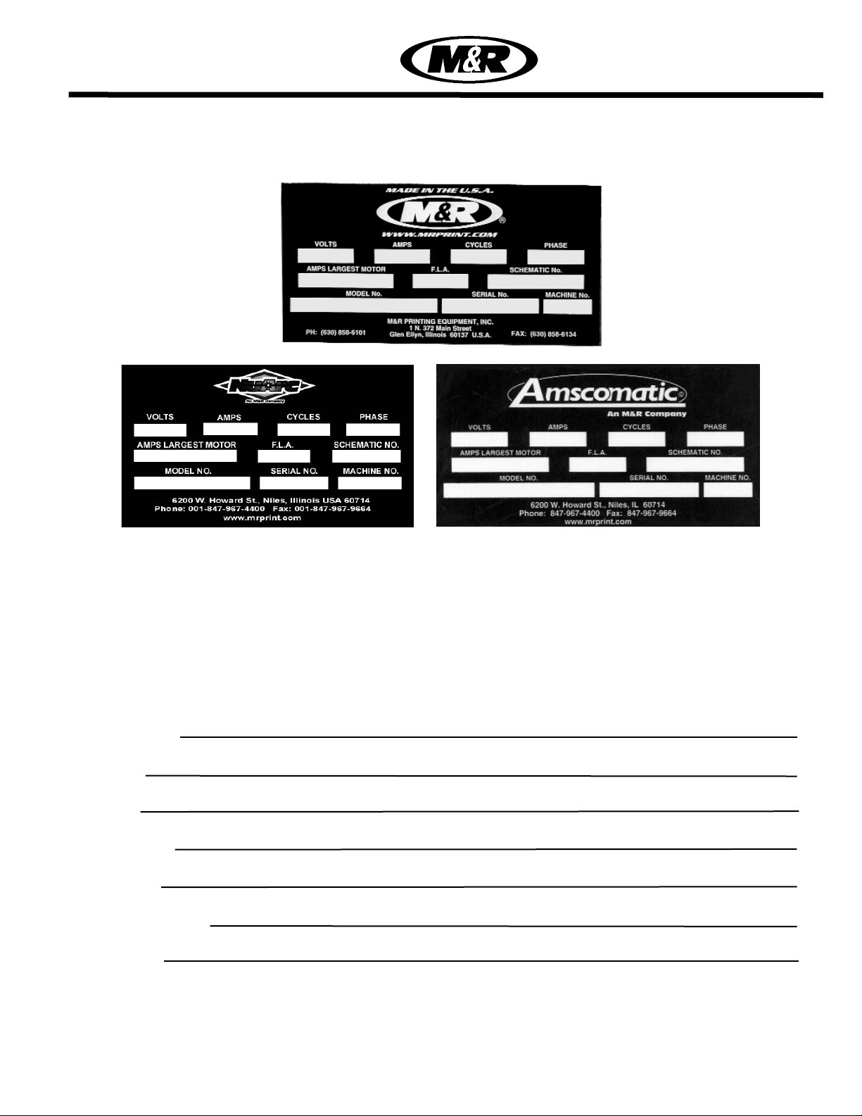
Each product manufactured by M&R Printing Equipment, Inc., or one of its subsidiaries, NuArc Company, Inc.
or Amscomatic Inc. includes a metal manufactures rating plate permanently fixed to the product as shown
above. The Manufacturers Rating Plate includes important information regarding the product, such as elec-
trical power requirements, Model No., Serial No. and schematic number.
In the event that replacement parts are to be ordered for any M&R, NuArc or Amscomatic product, always
supply the following information which can be found on the Manufacturers Rating Plate. This will help to
ensure that you receive the correct replacement part you require.
Product Name:
Model No.
Serial No.
Schematic No.
Machine No.
*Date of Installation:
*Installed By:
* Optional information (not required)
Challenger II
mrprint.com


Introduction
Valued Customer,
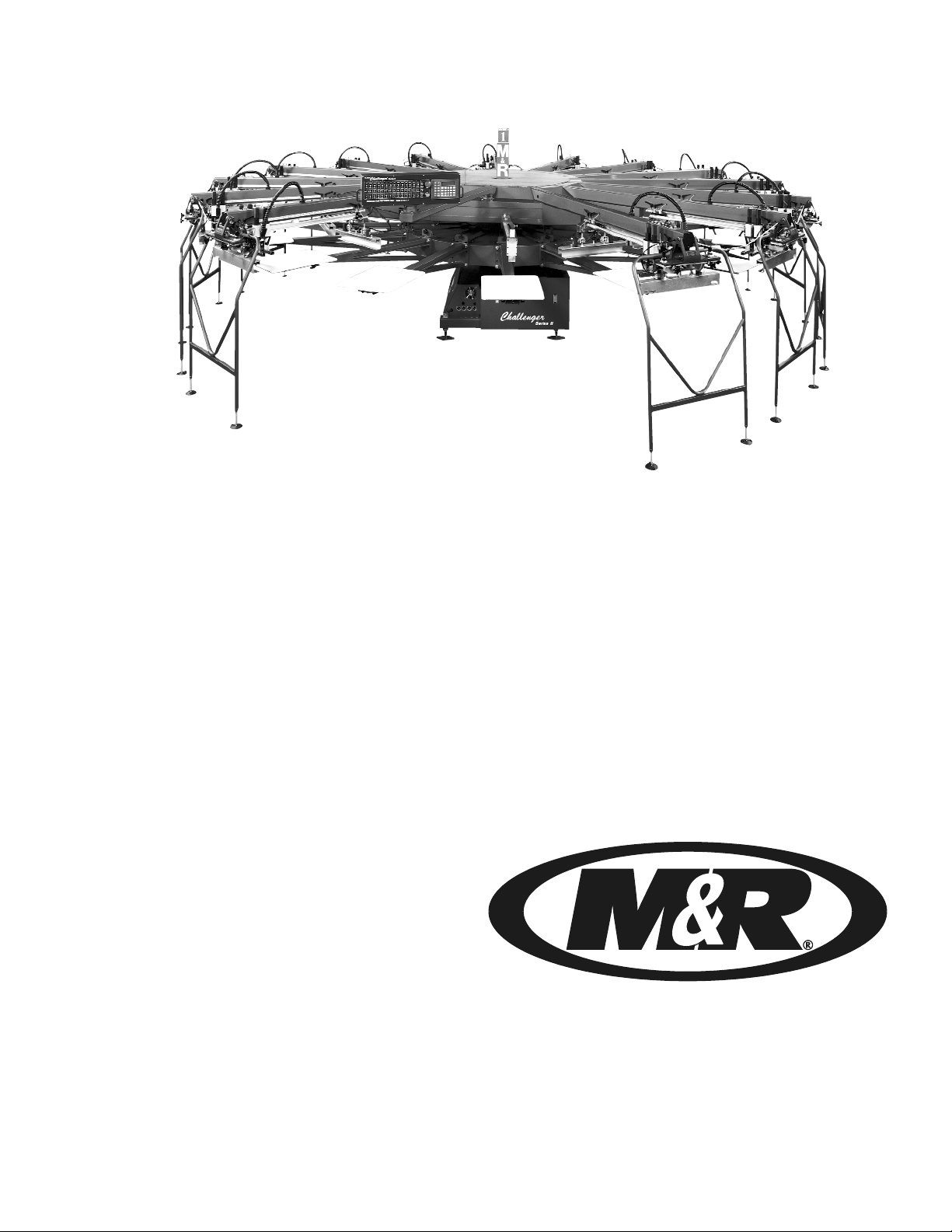
Thank you and congratulations on your purchase of your new M&R Challenger Series II semi-auto-
matic Textile Screen Printing System.
A thorough understanding of the operation and maintenance of your new M&R Challenger Series II will
insure maximum production rates and a long service life for your investment. This Operator’s Manual
is provided to help guide you, and your employees, in the proper procedures for set-up, operation and
preventive maintenance of your new M&R Challenger Series II.
Should you have any questions regarding the operation or maintenance of your new M&R Challenger
Series II, M&R’s world wide Technical Service and Support Network is available to you during regular
business hours (8:30am - 5:00pm C.S.T.) at 1 (800) 736-6431, International customers phone +847-
967-4461 or, on week ends or holidays, call our 24 hour Emergency Service Hotline at 1 (630) 462-
4715 for technical support 24 hours a day, seven days a week.
On behalf of all of us here at M&R, thank you for selecting M&R as your equipment supplier.
Michael J. Sweers
Director of Technical Services
M&R Printing Equipment, Inc.
M
&
R
P
r
i
n
t
i
n
g
E
q
u
i
p
m
e
n
t
,
I
n
c
.
W
o
r
l
d
w
i
d
e
T
e
c
h
n
i
c
a
l
S
e
r
v
i
c
e
N
e
t
w
o
r
k


Table of
Contents Disclaimer
Model Description
Introduction
Safety Precautions................................................1
Specifications........................................................5
Screen Frame & Image Size..................................9
Installation Instructions.......................................11
Set Up Instructions/Central Off-Contact............13
Operator Controls...............................................15
E 300 Operator Interface....................................25
Preventive Maintenance Procedures..................47
Pallet Leveling Procedure...................................71
Proximity Switch Location..................................75
Index Lift Cylinder Cushion Adj..........................78
Idec Relay Location............................................79
Trouble Shooting Procedure...............................83
Recommended Spare Parts...............................87
Replacement Parts............................................93
Warranty Information........................................
Glossary
Electrical Schematics
Challenger II
mrprint.com


Safety Precautions
M&R Printing Equipment, Inc. - Glen Ellyn, Illinois 1
SAFETY PRECAUTIONS
FUNDAMENTAL SAFETY INSTRUCTIONS:
Please read all information regarding safety precautions
as presented in the Operator’s Manual.
The fundamental requirement to assure safe and trouble-
free operation of this equipment, is a thorough understand-
ing of the safety information contained in this Operator’s
Manual.
This Operator’s Manual includes important instructions to
assure safe operation of this equipment. This Operator’s
Manual, and especially the safety instructions as described
there-in, must be observed by everyone who will operate
this equipment. In addition to the safety instructions and
regulations described in this Operator’s Manual, rules and
regulations of the equipment owners place of business
must also be observed.
Obligation of the Equipment Operator:
The equipment Operator is obliged to guarantee that only
staff who are acquainted with the fundamental regulations
according to workers protection and accident prevention,
and, are completely knowledgeable in the operation of this
equipment have fully read the Safety Chapter and the
Warning Instructions of this manual, and understand the
instructions as they relate to operation of this equipment.
Equipment Operators must be continually evaluated to
assure that they fully understand the operation of this
equipment.
Obligation of Personnel:
Every person that will be engaged in the operation of this
equipment must comply with the following before operation
of the equipment is to begin.
1. Observe the fundamental regulations of worker’s pro-
tection and accident prevention.
2. Read the Safety Chapter and Warning Instructions of
this Operator’s Manual and confirm by signature that they
understand the instructions as described in the manual.
Dangerous Situations during Operation of the
Equipment:
The M&R Challenger Series II has been designed and con-
structed in accordance with safety standards as described
by Nationally Recognized Testing Laboratories, such as
Underwriters Laboratories in the United States, and the
European Economic Community (CE) Standards and
Directives. However, it is possible that dangerous condi-
tions which can cause serious injury or loss of life for the
user or third persons, or damage to the equipment or prop-
erty could occur.
This equipment must be used only for the defined purpose
as described in the Operator’s Manual, and must be main-
tained in perfect running condition in accordance with
described Safety Regulations.
Conditions which may compromise operator safety must be
identified and corrected immediately.
Defined Purpose:
The M&R Challenger Series II is specifically designed to
apply (print) screen printed textile inks on textile substrates.
Any other use of the equipment which does not meet the
Defined Purpose as described above is not permitted.
In accordance with the Defined Purpose of this equipment,
it is necessary to observe all instructions as outlined in the
Operator’s Manual and to perform the preventive mainte-
nance procedures as described in the manual.
Guarantee and Liability:
In principle, our general terms of sale and delivery are valid
and these are at the Operator’s disposal. Guarantee and lia-
bility claims for persons or property damage are excluded if
they originate for one or more of the following reasons.
1. A non-defined use of the equipment
2. Improper installation or use of the equipment
3. Operation of the equipment with defective safety
devices
4. Non-Observance of instructions as described in the
Operator’s Manual for transportation, storage, instal-
lation, operation, maintenance, set-up and take-
down of the equipment.
5. Modification of the equipment.
6. Failure to replace worn or defective parts of the
equipment.
7. Defective repairs made to the equipment.
8. Dangerous conditions which are a result of the
improper use of the equipment.
Description of Safety Symbols and
Instructions:
This symbol signifies or alerts the
equipment operator of conditions
or areas of the equipment which
present imminent danger to the
health of the equipment Operator.
Non-observance of these
instructions has serious health
consequences, and can lead to
highly dangerous injuries.
DANGER!
Challenger II
mrprint.com

M&R Printing Equipment, Inc. - Glen Ellyn, Illinois
2
This symbol signifies a possible
imminent danger for life and health
of persons and equipment
Operators.
Non-observance of these
instructions can have serious
health consequences and can
lead to highly dangerous injuries.
This symbol signifies a possible
danger.
Non-observance of these
instructions can lead to light
injuries or damage to the equip-
ment or property.
This symbol gives important
instructions for the proper use of
the equipment.Non-observance
of these instructions can lead to
equipment failure.
This symbol is used to describe
operating tips or especially useful
information.
This information will enable the
Operator to use all equipment
functions for optimal perfor-
mance.
Organizational Measures:
Equipment operators are responsible to provide personal
protection when operating this equipment. All safety
devices must be checked each day before operation of the
equipment can begin.
Safety Devices:
Before beginning operation of the equipment, all safety
appliances must be checked for proper operation.
Safety devices may only be removed after.....
1. The equipment is shut down.
2. The electrical power has been dis-connected from the
equipment.
3. In case of delivery of partial components, the Operator
must install safety devices in accordance with regula-
tions.
Exploratory Safety Measures:
The Operator’s Manual must be kept on or near the equip-
ment at all times. All safety and danger notices must be kept
in readable condition at all times.
Training of Equipment Operator’s
Only properly trained Operators may run the equipment.
The competence of personnel who are to operate, maintain,
set-up and shut down the equipment must be confirmed.
Unskilled staff may work with the equipment only when
supervised by experienced equipment Operators.
Equipment Control System:
Never make any modifications to software.
Only experienced Operators may actuate the control sys-
tem.
Safety Measures during Normal Operation:
Operate the equipment only if all safety devices are fully
operational.
Before starting the equipment, check to be sure no-one will
be endangered by the operation of the equipment.
Check the equipment and safety devices at least once per
shift for external or visible damage.
Danger by Electrical Energy:
Work on the electrical system must
be carried out by qualified person-
nel only.
Check the electrical equipment
regularly for any sign of defect or
loose connections.
Electrical enclosures must be kept
securely locked at all times.
Only authorized personnel with a
key are allowed access to electrical
enclosures.
Danger by Pneumatic Energy:
Only personnel with experience with pneumatic power sys-
tems may work with pneumatic components or assemblies.
Before starting any work on pneumatic components or
assemblies, the compressed air supply must be com-
pletely drained from the equipment to prevent any oper-
ation of pneumatic controls or assemblies.
CAUTION!
i
IMPORTANT!
OPERATING
TIP!
DANGER!
WARNING!
Safety Precautions
Challenger II
mrprint.com

M&R Printing Equipment, Inc. - Glen Ellyn, Illinois 3
All pneumatic piping and/or hoses must be checked at reg-
ular intervals for signs of wear or failure.
Maintenance & Trouble Shooting:
Preventive maintenance must be performed at regular inter-
vals as described in the Operator’s Manual.
Equipment operator’s must be informed before any preven-
tive maintenance can be performed.
All power systems such as electrical, pneumatic,
hydraulic or mechanical must be dis-connected and
locked out before preventive maintenance may begin.
Structural Modification of the Equipment:
Modifications of equipment are specifically not allowed with
out written authorization from M&R Printing Equipment, Inc.
Cleaning of the equipment:
Clean away all ink or other contaminant’s at the end of each
day.
Equipment Noise:
Under normal operating conditions as described under
Defined Purpose, this equipment will not produce sound
above the level of 65 db. Depending on local conditions, a
higher continuous sound level may result that could lead to
hardness of hearing. In this case, the operational staff must
wear appropriate safety clothing or protection.
CAUTION: The information con-
tained in this Operator’s Manual
has been provided to eliminate
problems from occurring. Be sure
to read through this Operator’s
Manual fully before operating your
press.
There are numerous safety features
utilized in the operation of this
equipment. Please be sure you
know the location of these safety
devices and how they operate
before attempting to operate this
equipment.
SAFETY FEATURES -
1. All equipment is provided with either a safety bar, foot
switch, yellow safety cords, infrared safety beam, yellow
floor mats or hand switch to stop the equipment. Please
know the type on your equipment and its location and func-
tion before operating. NEVER ATTEMPT TO BY-PASS OR
DEFEAT ANY SAFETY DEVICE OR APPLIANCE. IN THE
EVENT THAT ANY OR ALL SAFETY DEVICES ARE NOT
OPERATING OR FUNCTIONING PROPERLY, DO NOT
ATTEMPT TO OPERATE THIS EQUIPMENT!
2. Safety guards have been provided to protect the opera-
tor from all moving parts. Please do not remove these
Safety Guards any time the equipment is in operation.
3. This Operator’s Manual includes information regarding
the proper preventative maintenance procedures. When
ever personnel are performing preventative maintenance
procedures, be sure that all electrical and pneumatic
power is disconnected from the equipment, and that
disconnects are locked in the “OFF” position.
4. Never work on the table surface under the print stations
unless the power “ON/OFF” switch is placed in the “OFF”
position.
OPERATOR SAFETY INSTRUCTIONS -
All industrial equipment, including screen printing equip-
ment, requires a combination of high electrical, pneumatic,
hydraulic or mechanical power for operation. In addition,
automatic screen printing equipment, by its nature, expos-
es operators to parts and assemblies which operate at high
speeds and contain numerous moving parts. As with all
complex industrial equipment, care should be exercised to
carefully observe proper operating procedures and safety
precautions.
Although every effort has been made to design and con-
struct safe, dependable equipment, it is impossible to fore-
see all circumstances under which this equipment may be
utilized, or to anticipate all possible combinations of factors
which may cause a hazardous condition or situation. It is
therefore imperative that the equipment Operator, as well as
all other personnel engaged in any phase of the set-up,
operation or preventative maintenance of this equipment
consider safety first an important part of their job.
The following general safety considerations are offered as
an aid to users of M&R Printing Equipment to assist them
in becoming safety conscience.
1. READ THE OPERATOR’S MANUAL before attempting
to lift, move, operate or perform maintenance on any piece
of machinery. Become intimately familiar with all equipment
controls, their locations, their operation and their effect on
equipment function. Keep this Operator’s Manual in a clean
location immediately adjacent to the equipment for a quick
and handy reference.
2. BEFORE ATTEMPTING TO START THE EQUIPMENT
inspect all areas around and adjacent to moving parts for
possible obstructions: tools, rags, crating remnants etc. Be
certain that all Safety Guards, covers, access doors etc., are
properly installed prior to starting operation.
CAUTION!
Safety Precautions
Challenger II
mrprint.com

Safety Precautions
M&R Printing Equipment, Inc. - Glen Ellyn, Illinois
3. PRACTICE GOOD HOUSEKEEPING: Maintain and area
adjacent to NOT ON the equipment for tool and color stor-
age. Clean up all spills and eliminate all potential trip points
from the operating areas around the equipment to prevent
slipping or falling into the working zone of the equipment.
Do not stand on equipment elements not intended for
this purpose. Maintain a maximum clear area around the
equipment for unobstructed movement of the Operator.
Perform Preventative Maintenance at the intervals specified
in this Operator’s Manual.
4. AVOID WEARING LOOSE CLOTHING , long hair, neck
ties etc., when operating this equipment as these can easi-
ly become entangled in moving parts. Safety shoes are like-
wise recommended. Avoid horseplay around the equip-
ment.
5. DO NOT ATTEMPT to operate this equipment if you are
sick, excessively fatigued or under the influence of alcohol
or prescription drugs. Shut off the equipment immediately if
any malfunction occurs or appears imminent. Report any
unsafe equipment or condition promptly in order that cor-
rection can be made as soon as possible.
6. BY-STANDERS should stay well away from the equip-
ment so as not to distract the operator or accidentally move
a control element. Avoid talking to the operator while the
equipment is in operation.
7. WHEN CHANGING SET-UP, performing maintenance
work, cleaning the equipment etc., it is imperative that the
main electrical and pneumatic power supplies be discon-
nected to avoid accidental operation and possible resultant
injury. This is particularly important in the event more than
one person is involved in such duties.
8. A WRITTEN SAFETY PROGRAM should be installed by
all companies owning M&R Printing Equipment. This pro-
gram should cover inspection, maintenance and safety
training on the proper use of the machinery.
WARNING! DO NOT WORK
WITHIN THE INDEX TABLE
OPERATING AREA UNLESS ALL
SAFETY PRECAUTIONS HAVE
BEEN OBSERVED!
4
WARNING!
Challenger II
mrprint.com

SPECIFICATIONS CHALLENGER Series II (Pneumatic Models)
M&R Printing Equipment, Inc. - Glen Ellyn, Illinois 5
MODEL No. 12 COLOR 14 COLOR
Maximum Image Size 20” x 28” (50 x 70 cm) 20” x 28” (50 x 70 cm)
Maximum Frame O.D. 26” x 43” (66 x 109 cm) 26” x 43” (66 x 109 cm)
Total Set-Up Diameter 18’ (5.49 m) 19’ 6” (5.94 m)
Compressed Air Req. 100 P.S.I. @ 62scfm 100 P.S.I. @ 72 scfm
Electrical Requirements 208/230 v, 3 ph, 17 Amps
50/60 Hz.
208/230 v, 3 ph, 17 Amps
50/60 Hz.
Shipping Weight 7600 lbs. (3447 kg) 8100 lbs. (3674 kg)
Standard Pallet Size 16” x 22” (40.6 x 55.8 cm) 16” x 22” (40.6 x 55.8 cm)
The electrical specifications indicated are based on mathematical calculations which
assume ideal conditions exist for electrical supply line values, material used in the
installation of electrical service and site preparation. Although every effort has been
made to provide accurate electrical specifications, M&R Printing Equipment, Inc., does
not assume any liability for damages, whether consequential or incidental, that may
result from the use of the indicated electrical specifications. M&R Printing Equipment,
Inc.,encourages the use of a licensed Electrician for the installation of electrical service
to this equipment. The equipment when installed must be electrically grounded in
accordance with local codes, or in the absence of local codes, with the National
Electrical Code ANSI/NFPA 70- Latest Edition.
M&R Printing Equipment, Inc. reserves the right to alter specifications in the manufac-
ture of its products.
Specifications
i
IMPORTANT!
16 COLOR
20” x 28” (50 x 70 cm)
26” x 43” (66 x 109 cm)
21’ (6.40 m)
100 P.S.I. @ 82 scfm
208/230 v, 3 ph, 17 Amps
50/60 Hz.
10110 lbs. (4586 kg)
16” x 22” (40.6 x 55.8 cm)
18 COLOR
20” x 28” (50 x 70 cm)
26” x 43” (66 x 109 cm)
22.6’ (6.9 m)
100 P.S.I. @ 92 scfm
208/230 v, 3 ph, 17 Amps
50/60 Hz.
12110 lbs. (5493 kg)
16” x 22” (40.6 x 55.8 cm)
Challenger II
mrprint.com

Specifications
The electrical specifications indicated are based on mathematical calculations which
assume ideal conditions exist for electrical supply line values, material used in the
installation of electrical service and site preparation. Although every effort has been
made to provide accurate electrical specifications, M&R Printing Equipment, Inc., does
not assume any liability for damages, whether consequential or incidental, that may
result from the use of the indicated electrical specifications. M&R Printing Equipment,
Inc.,encourages the use of a licensed Electrician for the installation of electrical service
to this equipment. The equipment when installed must be electrically grounded in
accordance with local codes, or in the absence of local codes, with the National
Electrical Code ANSI/NFPA 70- Latest Edition.
M&R Printing Equipment, Inc. reserves the right to alter specifications in the manufac-
ture of its products.
M&R Printing Equipment, Inc. - Glen Ellyn, Illinois
i
IMPORTANT!
6
SPECIFICATIONS CHALLENGER Series II (AC Models)
MODEL No. 12 COLOR 14 COLOR
Maximum Image Size 20” x 28” (50 x 70 cm) 20” x 28” (50 x 70 cm)
Maximum Frame O.D. 26” x 43” (66 x 109 cm) 26” x 43” (66 x 109 cm)
Total Set-Up Diameter 18’ (5.49 m) 19’ 6” (5.94 m)
Compressed Air Req. 100 P.S.I. @ 21scfm 100 P.S.I. @ 21 scfm
Electrical Requirements 208/230 v, 3 ph, 37 Amps
50/60 Hz.
208/230 v, 3 ph, 40 Amps
50/60 Hz.
Shipping Weight 7600 lbs. (3447 kg) 8100 lbs. (3674 kg)
Standard Pallet Size 16” x 22” (40.6 x 55.8 cm) 16” x 22” (40.6 x 55.8 cm)
16 COLOR
20” x 28” (50 x 70 cm)
26” x 43” (66 x 109 cm)
21’ (6.40 m)
100 P.S.I. @ 21 scfm
208/230 v, 3 ph, 44 Amps
50/60 Hz.
10110 lbs. (4586 kg)
16” x 22” (40.6 x 55.8 cm)
18 COLOR
20” x 28” (50 x 70 cm)
26” x 43” (66 x 109 cm)
22.6’ (6.9 m)
100 P.S.I. @21 scfm
208/230 v, 3 ph, 48 Amps
50/60 Hz.
12110 lbs. (5493 kg)
16” x 22” (40.6 x 55.8 cm)
Challenger II
mrprint.com

Specifications
M&R Printing Equipment, Inc. - Glen Ellyn, Illinois 7
A clean, moisture free compressed air supply is essential for the contin-
ued operation of the M&R Challenger Series II press. We strongly recom-
mend that a refrigerated air chiller be installed in the compressed air sup-
ply line to the Challenger Series II press to prevent moisture damage to
pneumatic seals, valves and air cylinders used in the operation of the print
carriage (See diagram above). Failure to use a refrigerated compressed air
chiller with this equipment may void the warranty for pneumatic compo-
nents such as air cylinders, valves and seals.
Figure 2 Typical Multiple Unit (Loop) Compressor-Chiller Layout
CAUTION!
Challenger II
mrprint.com

A clean, moisture free compressed air supply is essential for the contin-
ued operation of the M&R Challenger Series II press. We strongly recom-
mend that a refrigerated air chiller be installed in the compressed air sup-
ply line to the Challenger Series II press to prevent moisture damage to
pneumatic seals, valves and air cylinders used in the operation of the print
carriage (See diagram above). Failure to use a refrigerated compressed air
chiller with this equipment may void the warranty for pneumatic compo-
nents such as air cylinders, valves and seals.
CAUTION!
Figure 1 Typical Compressor-Chiller Layout
M&R Printing Equipment, Inc. - Glen Ellyn, Illinois
8
Specifications
Challenger II
mrprint.com

M&R Printing Equipment, Inc. - Glen Ellyn, Illinois 9
Screen Frame & Image Size
NOTE: Although every effort has been made to provide accurate screen
frame specifications, M&R Printing Equipment, Inc. does not assume
any liability for damages, whether consequential or incidental that may
result from the use or misuse of the indicated specifications. M&R
Printing Equipment, Inc. reserves the right to alter specifications in the
manufacture of its products.
Challenger II
mrprint.com

M&R Printing Equipment, Inc. - Glen Ellyn, Illinois
10
Screen Frame & Image Size
Use this chart to determine whether your existing screen frame can be used on the M&R Challenger Series II.
1. Locate where your frames width falls along the left side of the chart.
2. Now find where the frame length falls along the bottom of the chart.
As long as these two dimensions come together within the chart, the frame will fit on the press.
NOTE! 26” wide by 43” long is the maximum screen size when every print station is in use.
Challenger II
mrprint.com

Installation
M&R Printing Equipment, Inc. - Glen Ellyn, Illinois 11
The M&R Challenger Series II requires installation by an
M&R factory-trained service representative. The following
conditions must be addressed before a technician can be
scheduled for your installation.
Pre-Technician Checklist for Challenger II Installation:
• Uncrate your Challenger II and check for
any obvious damage.
• Using the Chart on page 5 or 6, determine
the space requirements for your
Challenger II. Position the base in the
center of this area.
• Have the compressor and dryer (chiller
unit) operational. Use 3/4" black pipe from
the compressor to press with a Shut-Off
Valve provided at the press.
• Refer to the Manufacturers Rating Plate
mounted to the control panel. Install the
required Electrical Service at the power
input contactor located in the electrical
enclosure on the indexer base assembly.
Do not connect to press at this time.
(See illustration below)
• If optional flash cure is to be used, install
the electrical service as indicated on the
Manufacturer’s Rating Plate at all the
positions where it might be used. Refer to
the Manufacturer’s Rating Plate on each
flash cure unit for specific electrical
requirements.
• Provide one 16", squeegee blade ready to
install at every station (size 1 7/8" x 3/8").
Please note, squeegee blades are not
provided with your press.
• A three-color minimum print job, with tight
registration, should be ready to run. Refer
to page 11 & 12 for the required screen
frame dimensions and image placement.
• Provide adequate assistance (labor) for the
M&R technician during the assembly.
NOTE: Grease and oil are shipped with all
new M&R Challenger Series II presses.
•Provide a grease gun with standard Zerk
fitting. Fill the grease gun with white
lithium grease. Have another grease gun
filled with Synthetic Teflon Grease. One
quart of 10W non-detergent oil also will be
required.
After assembling, completing registration and checking
general operation of the Challenger Series II, our Service
Representative will assist your production staff in setting up
a job for which you have screens prepared. He will super-
vise and instruct all designated personnel in the proper pro-
duction procedures. This includes instructions on the cor-
rect usage of controls and preventive maintenance
described in the following sections of this manual.
i
IMPORTANT!
NOTES:
Electrical Input Contactor
Earth Ground Terminal
Challenger II
mrprint.com

M&R Printing Equipment, Inc. - Glen Ellyn, Illinois
12
Installation Hardware
The hardware list shown below illustrates and describes all hardware required to assemble your Challenger Series II
screen printing system. The quantity is indicated for each available model size. Although a Factory Trained M&R Service
Representative will perform the original installation of this equipment, this hardware list can prove valuable should the
equipment be relocated or dis-assembled for any reason. If any of the hardware listed below is not included with the
equipment upon delivery, please contact our Customer Service Dept. at 1 (800) 736-6431 for assistance.
3047001 Sleeve Anchor
1/2” x 2-1/4” 4 4 4
3047000 Sleeve Anchor
5/16” x 2-1/2” 26 30 34
3009013 Socket Cap Screw
1/2” - 13 x 1-1/4” 36 42 48
3003003 Bolt FL Whiz Lok
1/2”-13 x 1” Long 56 64 72
3009047 Socket Cap Screw
1/4” - 20 x 1/2” Long 48 56 64
3001013 Button Socket Cap
10-24 x 1/2” Long 42 51 60
3055003 Self Drill (Sheet Metal Screw)
8 x 3/4” 12 14 16
3022001 Lock Washer
1/4” 48 56 64
3021000 SAE Washer 1/2”
Zinc Plated 36 42 48
Illustration Part No. Description
12
Color
14
Color
16
Color
4
38
54
80
72
69
18
72
54
18
Color
Challenger II
mrprint.com
This manual suits for next models
3
Table of contents
Other M&R Industrial Equipment manuals
Popular Industrial Equipment manuals by other brands

GSi
GSi PNEG-1829 owner's manual

CHART
CHART Nomad 830G MP product manual

Sun Microsystems
Sun Microsystems Netra ft 1800 Hardware installation manual

Ammeraal Beltech
Ammeraal Beltech uni chains uni NTB Series Instructions and installation

Pepperl+Fuchs
Pepperl+Fuchs KF DWB-1.D Series manual

Lintec
Lintec HX-0020J Series instruction manual