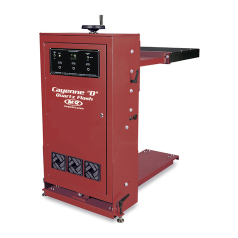
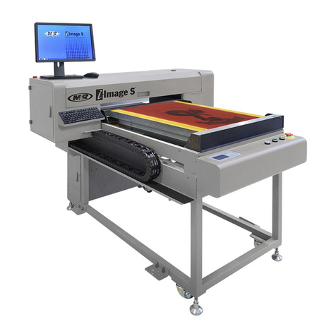
M&R Red Chili 1418 User manual

Red Chili™ Nv3
Part # MAN-REDCHILI
$95.00 USD
V.062414


M&R Companies 1N 372 Main St. Glen Ellyn, IL 60137 USA 3
Tel: +630-858-6101 Fax: +630-858-6134 www.mrprint.com | store.mrprint.com
V.062414
Contents
1. Safety and Operational Guidelines 4
1.1 Management Responsibilities..................................................................................................................5
1.2 Operator Responsibilities.........................................................................................................................6
2. General Information 7
2.1 Service and Parts.....................................................................................................................................8
2.2 Defined Purpose ......................................................................................................................................9
2.3 Warranty...................................................................................................................................................10
3. Specifications 11
4. Assembly and Installation 11
4.1 Assembly..................................................................................................................................................11
4.1.1 Quartz Heating Elements.............................................................................................................11
4.2 Installation................................................................................................................................................13
4.2.1 Install Photoelectric Sensor .........................................................................................................15
4.2.2 Install Press PLC Signal Cable....................................................................................................16
4.2.3 Install Foot Pedal .........................................................................................................................17
5. Operation 18
5.1 Control Panel ...........................................................................................................................................18
5.1.1 Digital Controller ..........................................................................................................................19
5.2 Operation Overview .................................................................................................................................22
5.2.1 Adjusting Photoelectric Sensor....................................................................................................22
6. Scheduled Maintenance 23
6.1 Scheduled Maintenance Log ...................................................................................................................28
7. Troubleshooting 29
8. Replacement Parts 31

4 M&R Companies 1N 372 Main St. Glen Ellyn, IL 60137 USA
Tel: +630-858-6101 Fax: +630-858-6134 www.mrprint.com | store.mrprint.com
V.062414
1. Safety and Operational Guidelines
DANGER
This symbol identifies situations that endanger people, property, and/or equipment. If such conditions exist,
the equipment must be shut down and all energy sources (electrical, gas, and pneumatic) must be disconnected,
purged, and locked out until the problem is resolved.
Never attempt to bypass or defeat any safety device. Do not attempt to operate the equipment if any safety
device is not functioning properly, or if any doubt exists about proper operation of safety devices.
The product described in this publication may operate at high speed and contain numerous moving parts.
It may employ natural gas or propane, mechanical or pneumatic forces, and/or hazardous voltages, and may
create other conditions that could, through misuse, abuse, unauthorized alteration or retrofitting, inattention, or
lack of understanding, result in injury, death, or damage to the product or to other equipment. In addition,
improper operation may also depreciate the value of the machine and other assets of the owner, and impair the
working efficiency of the machine.
Energy Sources
M&R equipment may use one of more of the following energy sources:
Compressed Air (Pneumatic Energy)
Electricity
Gas (Natural Gas or Propane)
Each form of energy presents its own unique hazards and requires appropriate precautions.
Danger From Compressed Air (Pneumatic Energy)
Only qualified personnel should be allowed to work on pneumatic components or assemblies. Before work is
started on pneumatic components or assemblies, equipment should be disconnected from the air supply and all
pneumatic lines should be purged to prevent accidental operation of pneumatic assemblies. All pneumatic pipes
and hoses should be checked frequently for damage and wear.
Danger From Electrical Energy
Only qualified personnel should have access to electrical enclosures or work on electrical systems, and
enclosures should be locked when not in use. Electrical equipment should be checked regularly.
Danger From Gas (Natural Gas or Propane)
Only qualified personnel should be allowed to work on gas components or assemblies. Before work is started on
gas components or assemblies, gas supply valve should be closed and locked. Gas pipes and equipment should
be checked regularly.
WARNING
Failure to follow safety and maintenance procedures or to take appropriate corrected action when required can
result in severe or fatal personal injuries, property damage, and/or damage to the equipment.

M&R Companies 1N 372 Main St. Glen Ellyn, IL 60137 USA 5
Tel: +630-858-6101 Fax: +630-858-6134 www.mrprint.com | store.mrprint.com
V.062414
1.1 Management Responsibilities
1. Ensure that this equipment is used only for the purposes set forth in the “Defined Purpose” section of
this manual.
2. Ensure that all employees involved with the operation of this equipment or working near it read,
understand, and act in accordance with the operational and safety standards set forth in this manual,
including the Operator Responsibilities listed below.
3. Ensure that all recommended preventive maintenance is carried out according to M&R guidelines.
4. Should any problem arise which compromises the safe operation or normal functioning of this
equipment, ensure that the equipment is immediately shut down, sources of power to the equipment are
shut off and secured, and that personnel not trained to repair - and directly involved in repairing - the
equipment are removed from the immediate area and not allowed to return until the equipment has been
returned to a safe and fully-functional condition.
5. Provide, and compel use of, any personal protection devices that may be required for the safe operation
of this equipment.
6. Make no modification to equipment or equipment software without written approval from M&R.
7. Provide - and support with written documentation - necessary employee training to ensure safe
operation, including but not limited to instruction in:
a. the operation of this machine
b. the use of personal protection devices
c. preventive maintenance procedures

6 M&R Companies 1N 372 Main St. Glen Ellyn, IL 60137 USA
Tel: +630-858-6101 Fax: +630-858-6134 www.mrprint.com | store.mrprint.com
V.062414
1.2 Operator Responsibilities
Note: 'Operator Responsibilities' pertain to all employees who work on or near the equipment; this
includes, but is not limited to those who clean, maintain and repair the equipment as well as those who
operate it. In general, all those who work on or near the equipment have a duty to use reasonable and
ordinary care for their own safety when in the vicinity of the machine. Failure to use reasonable and
ordinary care subjects people and property to serious personal injury and/or death and to destruction of
personal and/or company property. M&R expressly disclaims any and all liability, whether in contract, tort
or by statute, for damages, whether in the nature of personal injury/death and/or property damage, and
whether direct, indirect, consequential or incidental, as a result of a failure to use reasonable and
ordinary care.
1. Ensure that this equipment is used only for the purposes set forth in the “Defined Purpose” section of
this manual.
2. Read, understand, and act in accordance with the safety and operational standards and guidelines set
forth in this manual.
3. Install and maintain the equipment and safety devices in accordance with this manual; this includes
checking the equipment and safety devices for external or visible damage at least once per shift, and
making sure all safety and danger notices are in place and in readable condition.
4. Make no modification to equipment or equipment software without written approval from M&R.
5. Ensure that all other employees working on or near this equipment are knowledgeable in its safe
operation, and closely supervise inexperienced employees; keep bystanders away from the equipment.
6. Make sure the area around the equipment is clear and free of obstructions, clean up spills immediately,
and remove ink and other contaminants at the end of each shift.
7. Ensure that any and all safety guards (including but not limited to safety bar, foot switch, yellow cycle
interruption cords, infrared safety beam or hand switches) provided with this equipment for the purpose
of protecting personnel by automatically stopping the equipment are in place - and are not removed,
disabled or rendered ineffective during operation.
8. Wear any personal protection devices required for the safe operation of this equipment.
9. Avoid wearing anything that could become entangled in moving parts; for example, but not by way of
limitation, tie back, pin up, or cover long hair.
10. Do not attempt to operate this equipment if you are sick, fatigued, or under the influence of alcohol
and/or drugs including, but not limited to, prescriptions and over-the-counter medications that warn
against the operation of equipment.
11. Avoid standing on any part of the equipment not intended for that purpose.
12. Immediately shut down the equipment, disconnect and lock out all sources of power (electrical, gas,
and/or pneumatic); and purge all lines under pressure if the equipment fails to be fully operational or if
any safety device fails to operate properly, and ensure that the equipment stays offline until the safety
device is again operational.
13. Perform - and document - preventive maintenance at intervals described in the Operator's Manual.
14. Keep this Operator's Manual in clean, easily readable condition near the equipment at all times so it can
be quickly accessed by operators and maintenance personnel.

M&R Companies 1N 372 Main St. Glen Ellyn, IL 60137 USA 7
Tel: +630-858-6101 Fax: +630-858-6134 www.mrprint.com | store.mrprint.com
V.062414
2. General Information
This Document
This document is based on information available at the time of its publication. While every effort has been made to
be accurate, the information contained herein does not purport to cover all details or variations in hardware,
software, features, or specifications, or to provide for every possible contingency in connection with installation,
operation and maintenance. Features may be described herein which are not present in all models of this product.
M&R Printing Equipment, Inc. and its subsidiaries reserve the right to alter specifications in the manufacture of
their products, and they assume no obligation of notice to holders of this document with respect to changes
subsequently made.
M&R Printing Equipment, Inc. and its subsidiaries make no representation or warranty, expressed or implied,
whether pursuant to statute or case law with respect thereto, and assume no responsibility for, the accuracy,
completeness, sufficiency or usefulness of the information contained herein. No warranties of merchantability or
fitness for a particular purpose shall apply.
This is a publication of M&R Printing Equipment, Inc. and its subsidiaries. All information contained herein is
derived in part from proprietary and patent data of M&R Printing Equipment, Inc., and may not be copied,
electronically reproduced, or transmitted in any form without prior written permission, in each case made and
provided.
Any product names used in the documentation are used for identification only and may be trademarks of their
respective owners. The M&R Companies does not claim any rights to those marks.

8 M&R Companies 1N 372 Main St. Glen Ellyn, IL 60137 USA
Tel: +630-858-6101 Fax: +630-858-6134 www.mrprint.com | store.mrprint.com
V.062414
2.1 Service and Parts
Manufacturer's Rating Plate
Most products manufactured by the M&R Companies have a metal manufacturer's rating plate. Below is a label
imprinted with the information from your product's rating plate. Please be prepared to provide this information
when calling. This helps us respond to your needs more quickly.
If this is a replacement manual, please record the information from your product's rating plate on the sample plate
shown below.
Date Installed
Installed by
Optional Features and Special Information
Contacting M&R
If you need service or have questions about your equipment, call the appropriate number and ask for Technical
Support. If you need parts, ask for the Parts Department.
From the United States & Canada
Monday-Friday between 8:30 AM and 5:00 PM
Central Standard/Daylight Time
800-736-6431 Or 630-858-6101
From all other countries
Monday-Friday between 14:30 and 23:00
Greenwich Mean Time (GMT)
+847-967-4461
Outside Regular Hours
Call our Global Hotline:
+630-462-4715
Visit www.mrprint.com for a list of global
contacts
www.mrprint.com

M&R Companies 1N 372 Main St. Glen Ellyn, IL 60137 USA 9
Tel: +630-858-6101 Fax: +630-858-6134 www.mrprint.com | store.mrprint.com
V.062414
2.2 Defined Purpose
Textile Presses
Textile Presses are designed to print textile inks on textile substrates, as more fully set forth in the manual specific
to that product. Any other use of this equipment is not permitted.
Textile Dryers
Textile Dryers are designed to cure/dry textile inks on textile substrates, as more fully set forth in the manual
specific to that product. Any other use of this equipment is not permitted.
Graphic Presses
Graphic Presses are designed to print graphic inks on rigid and semi-rigid flat substrates, as more fully set forth in
the manual specific to that product. Any other use of this equipment is not permitted.
Graphic Dryers
Graphic Dryers are designed to cure/dry graphic inks on rigid and semi-rigid flat substrates, as more fully set forth
in the manual specific to that product. Any other use of this equipment is not permitted.
Exposure Equipment
Exposure Equipment is designed to produce photographic printing plates and printing screens, as more fully set
forth in the manual specific to that product. Any other use of this equipment is not permitted.
Folding and Packaging Equipment
Folding and Packaging Equipment is designed to fold, transport, and package textile materials, as more fully set
forth in the manual specific to that product. Any other use of this equipment is not permitted.
Ancillary Equipment
Ancillary Equipment is designed to perform specific operations related to processing and handling of substrates,
as more fully set forth in the manual specific to that product. Any other use of this equipment is not permitted.
Digital Equipment
Digital Printers are designed to print water based inks on textile substrates and screens, as more fully set forth in
the manual specific to that product. Any other use of this equipment is not permitted.

10 M&R Companies 1N 372 Main St. Glen Ellyn, IL 60137 USA
Tel: +630-858-6101 Fax: +630-858-6134 www.mrprint.com | store.mrprint.com
V.062414
2.3 Warranty
Limited Warranty
Your Warranty does not apply to damages sustained due to equipment misuse, whether intentional or negligent,
and such misuse may void your warranty. Misuse includes - but is not limited to - the items listed below. In
addition, M&R Printing Equipment, Inc. accepts no responsibility for personal injury or property damage caused by
misuse.
1. Use of the equipment for any non-defined purpose
2. Improper installation or use of the equipment
3. Operation of the equipment with defective safety devices
4. Operation of the equipment with safety devices removed, disabled, not working in whole or in part or in
any manner rendered ineffective for the purpose for which they were designed
5. Failure to comply with instructions for transportation, storage, installation, operation, maintenance,
setup, and take-down of the equipment as described in the Operator's Manual
6. Unauthorized modification of the equipment or equipment software
7. Failure to replace worn or defective parts
8. Failure to use M&R supplied replacement and repair parts
9. Defective repairs made to the equipment
10. Dangerous conditions which result from improper use of the equipment

M&R Companies 1N 372 Main St. Glen Ellyn, IL 60137 USA 11
Tel: +630-858-6101 Fax: +630-858-6134 www.mrprint.com | store.mrprint.com
V.062414
3. Specifications
Specifications 2
Red Chili 1418
Red Chili 1618
Red Chili 2024
Red Chili 2028
Red Chili 3244
Electrical
Requirements1
208/230 V, 1 ph,
40 A
50/60 Hz, 9 kW
208/230 V, 3
ph, 23 A
50/60 Hz, 9 kW
380/415 V, 3 ph,
14 A
50 Hz, 9 kW
208/230 V, 1 ph,
40 A
50/60 Hz, 9 kW
208/230 V, 3 ph,
23 A
50/60 Hz, 9 kW
380/415 V, 3 ph,
14 A
50 Hz, 9 kW
208/230 V, 3 ph,
34 A
50/60 Hz, 14.4 kW
380/415 V, 3 ph, 21
A
50/60 Hz, 14.4 kW
208/230 V, 3 ph,
45 A
50/60 Hz, 19.3
kW
380/415 V, 3 ph,
27 A
50/60 Hz, 19.3
kW
-
380/415 V, 3 ph, 67
A, 50/60 Hz, 39.6
kW
Overall Size (H
x W x L)
114 x 58 x 107
cm (45” x 23" x
42”)
114 x 58 x 107
cm (45” x 23" x
42”)
109 x 58 x 112 cm
(43” x 23" x 44”)
109 x 58 x 122
cm (43” x 23" x
48”)
109 x 102 x 165 cm
(43" x 40" x 65")
Curing Area
36 x 46 cm (14”
x 18”)
41 x 46 cm (16” x
18”)
51 x 61 cm (20” x
24”)
51 x 71 cm (20"
x 28")
81 x 112 cm (32" x
44")
1Incoming voltage differs from the voltage(s) listed, calculate amperage accordingly. Other electrical
configurations are available: Contact M&R for details.
2Confirm the latest specifications on our website, www.mrprint.com .
4. Assembly and Installation
Inspection
Carefully inspect for signs of damage in transit. If equipment has been damaged in transit, notify the Freight
Forwarder immediately. M&R is not responsible for damage that occurs during transportation.
Hardware and Tools
Included with this unit is the required assembly hardware. Additional tools required: Blade Screwdriver, Tape
Measure.
4.1 Assembly
The unit is supplied with a standard line cord, however an electrical plug rated for the correct electrical service
must be installed by a licensed electrician.
4.1.1 QuartzHeating Elements
Avoid Heating Element Damage
Oily or foreign substances will damage the heating element. In case of contact, wipe the surface with Isopropyl
Alcohol. Always wear lint-free gloves when handling the heating element.

12 M&R Companies 1N 372 Main St. Glen Ellyn, IL 60137 USA
Tel: +630-858-6101 Fax: +630-858-6134 www.mrprint.com | store.mrprint.com
V.062414
WARNING: Never operate the unit when placed on its side. In this position, the Quartz
Heating Element filaments (1) compress and arcing results in premature failure of the element filament.
Always operate the unit with the Quartz Heating Elements in the horizontal (normal operating) position.
1. The Quartz Heating Element has a female electrical connector at both ends (1). Hold the Quartz
Heating Element near both ends and push the female electrical connector onto the spring socket (2).
2. Place the opposite end of the Quartz Heating Element on the spring socket (1) on the other side of the
Reflector Assembly. Allow the spring loaded pressure to hold it in position.
3. Install the remaining Quartz Heating Elements as described in the previous steps.

M&R Companies 1N 372 Main St. Glen Ellyn, IL 60137 USA 13
Tel: +630-858-6101 Fax: +630-858-6134 www.mrprint.com | store.mrprint.com
V.062414
4.2 Installation
WARNING: Before entering between print heads, always push in Emergency Stop button
and disconnect Cycle Interruption Cords.
Adjust Front and Rear Proximity Switches
1. Move the front and rear proximity switches, print carriage, rear frame holder, as far as they will go
toward the rear of the print head.
Note: Proximity adjustments for Challenger III presses are made through the Operator Interface.
Detailed instructions can be found in the press operator's manual.
2. Reset the Emergency Stop button and connect the Cycle Interruption Cords. From the main control
panel, turn off the print station that the unit will be installed on. Detailed instructions can be found in the
press operator's manual.
3. Unlock the front frame holder assembly on the print head and move it into the locked upright position.
WARNING: Do not attempt to install the unit if the front frame holder assembly does not
lock into position.
Note: This step does not apply to the Diamondback press.

14 M&R Companies 1N 372 Main St. Glen Ellyn, IL 60137 USA
Tel: +630-858-6101 Fax: +630-858-6134 www.mrprint.com | store.mrprint.com
V.062414
4. With the pallets in the “UP” position, position the unit into the print station so that the Quartz Heating
Elements are centered over the pallet. Lock the four Swivel Casters by pushing down on the Caster
Locks (1).
5. Dimensions between the surface of the Quartz Heating Elements and the pallet surface should be
approximately 2-1/4” (5.7 cm). Proper distance is determined by the type of ink used and the type and
weight of the substrate.
Note: Run a few tests to determine the proper distance before beginning production.
To adjust the height, loosen the Lock Handle (2). Lift the handle (Model 1418) up or turn the Height
Adjustment Wheel (1) clockwise to raise the unit or counterclockwise to lower the unit. Tighten the Lock
Handle (2) to lock in position.

M&R Companies 1N 372 Main St. Glen Ellyn, IL 60137 USA 15
Tel: +630-858-6101 Fax: +630-858-6134 www.mrprint.com | store.mrprint.com
V.062414
4.2.1 Install Photoelectric Sensor
Place the Press PLC/ Foot Pedal/Flash Sensor switch down in the Flash Sensor position (1).
The Photoelectric Sensor (1) on your unit is designed to activate the Quartz Heating Elements by sensing the
leading edge of the pallets as they are indexed around the press. The Photoelectric Sensor is installed at the
factory on the right side of the unit for use on presses set up for clockwise rotation.
For presses set up for counterclockwise rotation, the Photoelectric Sensor should be installed on the left side of
the unit.
Remove the 2 screws and nut (2) that hold the Photoelectric Sensor to the Mounting Bracket and the screw that
holds the Cable Fastener (3).
Remove the 2 screws that hold the bracket (4). Reinstall the Cable Fastener, Bracket and Sensor on the left side
of the unit using the mounting holes provided.

16 M&R Companies 1N 372 Main St. Glen Ellyn, IL 60137 USA
Tel: +630-858-6101 Fax: +630-858-6134 www.mrprint.com | store.mrprint.com
V.062414
4.2.2 Install Press PLC Signal Cable
The unit is designed to receive operational signals from the flash sensor mounted on the unit, foot pedal or the
press PLC.
WARNING: Ensure none of the pallets are positioned under the unit for an excessive
amount of time while the unit is on. Extreme heat can damage pallets, garments and/or cause a fire.
1. Place the Press PLC/Foot Pedal/Flash Sensor switch up in the Press PLC position (1).
2. Install the signal cable from the socket (1) on the unit to the plug socket (2) located on the lower
electrical enclosure of the press. The remaining plugs are for installation of additional unit systems.

M&R Companies 1N 372 Main St. Glen Ellyn, IL 60137 USA 17
Tel: +630-858-6101 Fax: +630-858-6134 www.mrprint.com | store.mrprint.com
V.062414
4.2.3 Install FootPedal
The unit is designed to receive operational signals from the flash sensor mounted on the unit, foot pedal or the
press PLC.
WARNING: Ensure none of the pallets are positioned under the unit for an excessive
amount of time while the unit is on. Extreme heat can damage pallets, garments and/or cause a fire.
1. Place the Press PLC/Foot Pedal/Flash Sensor switch in the center or Foot Pedal position (1).
2. Connect the foot pedal cable to the socket (1) on the unit.
3. Index the printed garment to the flash position. Depress and release the Foot Pedal to start the flash
unit. When the Flash Timer reaches 0, the unit turns off.

18 M&R Companies 1N 372 Main St. Glen Ellyn, IL 60137 USA
Tel: +630-858-6101 Fax: +630-858-6134 www.mrprint.com | store.mrprint.com
V.062414
5. Operation
5.1 Control Panel
Number
Name
Function
1
Power On/Off Switch
The Power On/Off switch supplies electrical power to the unit.
Place the switch in the On position to turn on.
Place the switch in the Off position to turn off.
2
Digital Controller
The Digital Controller selects output power, exposure time and lamp section
selection. The controller also selects 50 or 60 Hz. electrical supply frequency.
3
Press PLC
Foot Pedal
Flash Sensor
The Press PLC/ Foot Pedal/Flash Sensor switch allows the unit to receive a
signal from the adjustable Flash Sensor mounted on the unit or from the Press
PLC or Foot Pedal.

M&R Companies 1N 372 Main St. Glen Ellyn, IL 60137 USA 19
Tel: +630-858-6101 Fax: +630-858-6134 www.mrprint.com | store.mrprint.com
V.062414
5.1.1 Digital Controller
Red Chili 2024, 2028 uses an alpha/numeric digital controller to control flash time, quartz heating element section
use and power output.
Power Output and Exposure Time
Place the Power switch in the On position. The control displays the Power Output Setting on the top line and the
Flash Exposure Time on the lower line.
F1 Power Output
Press F1 to set the range of power. The range of power may be set from a minimum of 1% to a maximum of
100%. Press the arrow up (increase) and arrow down (decrease) buttons to change the temperature setting.
Note: When the control returns to standby mode, the current Power Output Setting and the Flash
Exposure Time display.

20 M&R Companies 1N 372 Main St. Glen Ellyn, IL 60137 USA
Tel: +630-858-6101 Fax: +630-858-6134 www.mrprint.com | store.mrprint.com
V.062414
F2 Time
Press F2 to set the Flash Exposure Time. The minimum flash time is 0.5 seconds and the maximum is 10
seconds. The current flash time displays on the lower line. Press the arrow up (increase) and arrow down
(decrease) buttons to change the flash time.
Note: The flash time on the digital controller should be set for the maximum of 10 seconds when
operating in the PLC mode. This is due to the fact that whichever timer (flash exposure time on the press
or flash exposure time on the flash cure) is set for the shorter time will control the flash shut-down.
F3 Section
The quartz heating elements are arranged in three sections: OUTSIDE (O), CENTER (C) and INSIDE (I). Press
F3 to select lamp sections for curing operation; the control displays SECT on the top line, and O C I on the lower
line. O C I displayed indicates that all three sections are operating.
To deselect a section, press F3 until the section letter flashes. Press the arrow down button; the indication
changes to a dash "-" and the section is now inoperative.
F3 Section (Red Chili 1418, 1618)
The quartz heating elements are arranged in three sections: LEFT (L), CENTER (C) and RIGHT (R). Press F3 to
select lamp sections for curing operation; the control displays SECT on the top line, and L C r on the lower line.
L C r displayed indicates that all three sections are operating.
To deselect a section, press F3 until the section letter flashes. Press the arrow down button; the indication
changes to a dash "-" and the section is now inoperative.
This manual suits for next models
4
Table of contents
Other M&R Industrial Equipment manuals
