Manusa Op. Visio L1H User manual
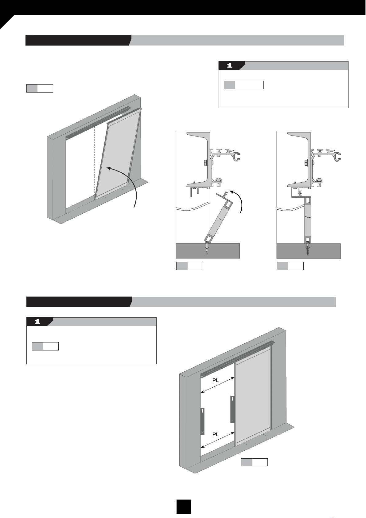
DMJOIL101EN - v1 VISIO L1H OPERATOR - INSTALLATION MANUAL
1
Installation manual
Op. Visio L1H

DMJOIL101EN - v1 VISIO L1H OPERATOR - INSTALLATION MANUAL
2
INSTALLATION MANUAL
VISIO L1H OPERATOR
TRANSLATED DOCUMENT
Read thoroughly all of these instructions before using
the unit.
This manual includes all the necessary information
required to install the product.
Keep this manual in a safe place for future reference.
0. INDEX

DMJOIL101EN - v1 VISIO L1H OPERATOR - INSTALLATION MANUAL
3

DMJOIL101EN - v1 VISIO L1H OPERATOR - INSTALLATION MANUAL
4
Fig. 1.1
Abr DESCRIPTION FORMULA
HL DOOR CLEAR HEIGHT
PL DOOR CLEAR WIDTH
AT OVERALL OPERATOR WIDTH
HM SLIDING LEAF HEIGHT HM=HL
HF FIXED LEAF HEIGHT HF=HL
AM SLIDING LEAF WIDTH AM=PL+Sp
AF FIXED LEAF WIDTH AF=AH-PL
HV BEAM HEIGHT HV=HL+28
HT OVERALL DOOR HEIGHT HT=HL+125
HR MINIMUM CEILING HEIGHT HR=HT+(5 min)
Dt TOTAL DOOR DEDUCTION Dt=Dop+S1+S2
S2 MINIMUM SAFETY DISTANCE HEAD AND BODY AS PER DET 2.4.1
S1 MINIMUM SAFETY DISTANCE HANDS AND FINGERS AS PER DET 2.4.2
Sp* OVERLAP FIXED LEAF / SLIDING LEAF DEP. ON FRAME
Dop * OPERATOR DEDUCTION DEP. ON FRAME
Check that the dimensions correspond to the order.
(See delivery note.) AT x HL ; PL
AH, Opening Width =
HV, Beam Height =
Fig. 1.1
1.2 INSTALLATION DIMENSIONS
Sp* Overlap between door leaves depending on
frame:
Frame 20,30,35,40 = 40
Frame 44 = 95
Dop * Operator deduction depending on frame:
Frame 20,30,35,40 = 50
Frame 44 = 100
Frame SOS 44 = 150
1.1 LEGEND AND FORMULAE
1. INSTALLATION DIMENSIONS AND CHECKS

DMJOIL101EN - v1 VISIO L1H OPERATOR - INSTALLATION MANUAL
5
1.4.2DET
1.2
AH Opening width
PL = (AH-Dt)/2 Clear width
AT = PL/2 + Dt Overall operator width
AM = PL + Sp Sliding leaf width
AF = AH-PL Fixed leaf width
1.3
1.4.1
1.4.2
1.4
1.4.1DET
Fig.
DET
DET
Fig.
Fig.
Fig.
1.2
S1* Safety distances depending on Frame:
S2* Safety distance depends on S as follows: For D20,T20,F20,R20,T35,D35 S1 = 0mm
For E20 S1 = 50mm
For I30 S1 = 55mm
For C44 S1 = 105mm
For S44 S1 = 105mm
If S <250 S2 = 200 mm
If S ≥250 S2 = 500 mm
1.3.1 Door width.
1.3 DOOR DIMENSIONS

DMJOIL101EN - v1 VISIO L1H OPERATOR - INSTALLATION MANUAL
6
1.6.1
1.5 1.6
1.6.1
1.7
1.8
1.9
5 min
Fig.
Fig.
Fig.
DET
Fig.
Fig.
DET
Ceiling line
HL Door clear height
HT = HL + 125 Overall door height
HR = HT + (5min) Minimum ceiling height
HV = HL + 28 Beam height
1.5 1.6
Check the floor level, beam and walls overhang.
FIG 1.7
Check AH for the whole opening as per Fig 2
Check that minimum HV = HL+28 for the whole
opening
Fig.
Fig.
Fig.
1.4 CHECKS
Fig.Fig.
1.3.2 Door height.
1.8
1.9

DMJOIL101EN - v1 VISIO L1H OPERATOR - INSTALLATION MANUAL
7
Herramientas
Broca nº9
10 mm approx.
Keep a distance of 10mm to the right and left of the
main profile.
Fig. 2.5
1. Track profile Length = AT-20mm
2. Insulation profile Length = AT-20mm
Fig. 2.4
Fig. 2.5
Fig. 2.4
2.2.2 Position.2.2.1 Introduce.
2.2 TRACK PROFILE ASSEMBLY
Drill hole size Ø9 along main profile as shown in
diagrams.
Fig. 2.2Fig. 2.1
Tools
Drill bit no.9
Fig. 2.3
Fig. 2.2
Fig. 2.1
Space drill holes
2.1 DRILLING
2. PREPARE MAIN PROFILE

DMJOIL101EN - v1 VISIO L1H OPERATOR - INSTALLATION MANUAL
8
Fig. 2.8
Fig. 2.7
Use a previously assembled trolley as
shown in the diagram.
Adjust the top wheel as shown in diagram.
Introduce the trolley on the top stile as
shown in diagram.
Slide the trolley along the whole length of
the main profile as shown in the diagrams.
Use a hand to help position the track rail.
Fig. 2.8
Fig. 2.7
Fig. 2.6
Fig. 2.6
Fig. 2.6
2.3 ADJUST TRACK PROFILE

DMJOIL101EN - v1 VISIO L1H OPERATOR - INSTALLATION MANUAL
9
3.2 TOP LINTEL ASSEMBLY
Reference vertical
Nuts & bolts
DIN7504N
Make marks in the top lintel as shown in
the diagram.
Self thread top lintel to the C-beam x10
self-threading screws placed at equal
intervals along the length of the profile, as
shown in the diagrams.
Fig. 3.3Fig. 3.3
Fig. 3.2
Fig. 3.4
Fig. 3.3Fig. 3.2
3.2.1 Mark and screw.
Fig. 3.1
Set out the sections as shown in the diagram.
Fig. 3.1
3.1 PROFILES LAYOUT
3. MAIN PROFILE AND TOP LINTEL ASSEMBLY

DMJOIL101EN - v1 VISIO L1H OPERATOR - INSTALLATION MANUAL
10
Reference vertical
Fig. 3.10Fig. 3.9
Screw main profile to the UPN as shown in the
diagrams.
Fig. 3.10Fig. 3.9
Nuts & bolts Nuts & bolts
DIN6923 M8 SO7380 M8×20
3.3.3 Screw.
Drill where marked along the length of the UPN at Ø8,
as shown in the diagrams.
Fig. 3.8Fig. 3.7
Herrramientas
Drill Ø8
Fig. 3.8Fig. 3.7
3.3.2 Drill.
Fig. 3.5
Drill holes in the beam using the main profile
as template, as shown in the diagrams.
Fig. 3.6Fig. 3.5
Fig. 3.6
3.3.1 Introduce and mark.
3.3 MAIN PROFILE ASSEMBLY

DMJOIL101EN - v1 VISIO L1H OPERATOR - INSTALLATION MANUAL
11
Woodw. E20 Woodw. D35 Woodw. 40 Woodw. I30 Woodw. 44
Drill section A as shown in the diagram.
See table for different frame
dimensions.
Fig. 4.3
Fig. 4.3
Tools
Drill bit no. 8’5/5
Cut section at A and B.
A = AF - 40
B= PL + 40
AF Fixed Leaf width, PL Clear
Fig. 4.2.1
Fig. 4.1
Fig. 4.2
Fig. 4.4
4.1.2 Drill.
Det.
4.1 MOUNT LOWER LINTEL.
4.1.1 Cut.
4. BOTTOM LINTEL PREPARATION

DMJOIL101EN - v1 VISIO L1H OPERATOR - INSTALLATION MANUAL
12
Woodw. E20 Woodw. D35 Woodw. I30 Woodw. 40 Woodw. 44
Nuts & bolts
DIN6923 M8
Fig. 4.4
4.1.3 Screw.
Screw the bottom lintel to the fixed leaf as shown in the diagram.
Leave 40mm in the PL part of the door leaf.
Check table for different frame dimensions.
Fig. 4.4

DMJOIL101EN - v1 VISIO L1H OPERATOR - INSTALLATION MANUAL
13
Woodw. E20 Woodw. D35 Woodw. I30 Woodw. 40
DET 5.2.2
Fig. 5.1
Fig. 5.2
Tools Nuts & bolts Nuts & bolts
Drill bit no. 6 DIN912 6x20 Rawlplug S-6
Variable depending on frame dimensions
Reference vertical
Reference vertical
Reference vertical
Reference vertical
Reference vertical
Reference vertical
Mark and drill the floor on the inside of the AT in
accordance with dimensions.
Mark and drill with respect to the reference vertical,
according to frame dimensions
Fig. 5.2 DET 5.2.1
Fig. 5.1
5.1 MOUNT FIXED LEAVES
5.1.1 Drill.
5. FIXED LEAVES / BOTTOM LINTEL (PL) ASSEMBLY

DMJOIL101EN - v1 VISIO L1H OPERATOR - INSTALLATION MANUAL
14
Fig. 5.6
Fig. 5.5
Fig. 5.4
Fig. 5.3
Check door leaves (PL) are parallel throughout the
clear height.
Fig. 5.6
Position the fixed leaves as shown in the diagrams.
Fig. 5.3/5.4/5.5
5.1.2 Position fixed leaves.
5.1.3 Check for plumb.

DMJOIL101EN - v1 VISIO L1H OPERATOR - INSTALLATION MANUAL
15
Fig. 5.11
Fig. 5.10
Tornilleria
D-7504N 4,2x16
Fig. 5.9
Fig. 5.9 / 5.10 / 5.11
Fig. 5.8
Fig. 5.7
Nuts & bolts
D-7504N 4,2x16
Screw (x3) fixed leaves to top lintel.
Fig. 5.7/5.8
Screw (x3) bottom lintel (PL) to top lintel.
5.1.4 Screw.
5.2.1 Screw.
5.2 BOTTOM LINTEL (PL) ASSEMBLY

DMJOIL101EN - v1 VISIO L1H OPERATOR - INSTALLATION MANUAL
16
6.2
6.1
6.3 6.4 Fig.Fig.Fig.
Fig.
Fig.
6.5
Insert 4 nuts distributed in the AT as shown in
the diagram.
Insert the nuts in the bottom channel of the main
profile.
Introduce lateral end stops and screws/nuts
into main profile. 6.3
Position stops at the two ends of the main
profile. 6.4
Screw to the nut inside the channel, and tighten
the screw over the track rail.
6.5
DIN7380 6x10 DIN6798 M-6DIN933 6x12
Nuts & bolts Nuts & bolts Nuts & bolts
Fig.
Fig.
Fig.
6.1.2 Lateral stops assembly.
Fig.
Fig. 6.1
6.2
6.1.1 Insert nuts into profile.
6.1 LATERAL STOPS ASSEMBLY
6. LATERAL STOPS / LOCK ASSEMBLY

DMJOIL101EN - v1 VISIO L1H OPERATOR - INSTALLATION MANUAL
17
Nuts & bolts Nuts & bolts
DIN7380 6x10 DIN6798 M-6
Fig. 6.8
Fig. 6.7
Fig. 6.6
Fig. 6.8
Fig. 6.7
Fig. 6.6
6.2 LOCK ASSEMBLY.
Introduce lock and screws/nuts into centre of
main profile.
Position the lock at AT/2.
Screw nuts inside channel.

DMJOIL101EN - v1 VISIO L1H OPERATOR - INSTALLATION MANUAL
18
Nuts & bolts
PFH M6x10
Nuts & bolts
D6334 M6x18
7.2
Fig.
Screw separators to trolleys no. 1
according to the layout shown in the
diagrams. Fig. 7.3 Fig. 7.4
Fig. 7.4
Fig. 7.3
7.1.2 Separators on trolleys assembly.
See the distribution of trolleys as per the scheme shown in
the diagram.
For an easy assembly number them 1 to 2.
Fig. 7.1
Fig. 7.2
Fig. 7.1
7.1.1 Distribute the trolleys in the operator
7.1 TROLLEYS ASSEMBLY.
7.1.1 Distribute the trolleys in the operator
OPENING TO THE LEFT. OPENING TO THE RIGHT.
Fig. 7.2
Fig. 7.1
7.1.2 Separators on trolleys assembly.
Fig. 7.3
Fig. 7.4
7. DRAGGING TROLLEYS / ARMS ASSEMBLY.

DMJOIL101EN - v1 VISIO L1H OPERATOR - INSTALLATION MANUAL
19
Attach lock hooks to trolleys 2-3 as
shown in the diagrams.
Fig. 7.9
DET 7.9.1
DET 7.9.1
Fig. 7.8
Fig. 7.7
Introduce the 2 trolleys into the main
profile as shown in the diagrams.
Adjust the top wheel in the 2 trolleys
as shown in the diagrams.
Fig. 7.9 DET 7.9.1
Fig. 7.7 Fig. 7.8
7.2 INTRODUCE TROLLEYS INTO MAIN PROFILE
Fig. 7.6
Tools Nuts & bolts
DIN7380 6x10 DIN6798 M-6
Fig. 7.5
7.1.3 Lock hooks assembly.
OPENING TO THE LEFT. OPENING TO THE RIGHT.
7.1.3 Lock hooks assembly.
Fig. 7.5
Fig.
7.5 7.6
Fig.
Fig. 7.6

DMJOIL101EN - v1 VISIO L1H OPERATOR - INSTALLATION MANUAL
20
Screw right hand arm to right hand
trolley (1) as shown in the diagram.
Fig. 7.13
Nuts & bolts Nuts & bolts
DIN7380 6x10 DIN6798 M-6
Fig. 7.13
7.3.3 Arms on trolleys assembly.
Fig. 7.10
7.3.1 Cut arms.
7.3 DRAGGING ARMS ASSEMBLY.
7.3.2 Arms on trolleys assembly.
OPENING TO THE LEFT. OPENING TO THE RIGHT.
7.3.2 Arms on trolleys assembly.
Cut arms as shown in diagram..
Fig. 7.10
Fig. 7.11 Fig. 7.12
7.11
DET
Screw anchors to arms as shown
in diagram. 7.12
DET
OPENING TO THE RIGHT.
Table of contents
Other Manusa Door Opening System manuals
Popular Door Opening System manuals by other brands

Hettich
Hettich Top Line 110 Assembly

Allegion
Allegion LCN 8310-836T quick start guide

TPG
TPG AXIM PR-7000 Series Technical support

C.R. Laurence
C.R. Laurence CRL JACKSON 1295 installation instructions

CornellCookson
CornellCookson AlarmGard FST-EPBD Series Installation instructions and operation manual

Assa Abloy
Assa Abloy Adams Rite EX89 Preparation guide