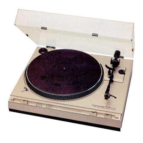
Marantz JJ4000 Setup guide

NT
LE
AUTOMATIC
TURNTAB
A
ENTRAINEME
2
‘
MI
AUTOMATIQUE
a
ENER
HALB-AUTOMATISCHER
PLATTENSPIELE!
cxcomnaal
a
—
inom
=<,
9
ieee
=
Cuamed
Bases
=
=
joo
52
=o
=
=
beckladl

INTRODUCTION
Please
read
this
owner’s
manual
thoroughly
to
ensure
correct
setup
and
operation
of
your
new
turntable.
DESIGNATION
OF
PARTS
1.
Socket
for
10.
Reject
Button
Optional
Extra
11.
Speed
Selector
Headshell
Switches
2.
Counterweight
12.
Platter
Mat
3.
Counterweight
13.
Turntable
Dial
Spindie
4.
Anti-skate
14.
Platter
Control
15.
45
RPM
5.
7
searm
Rest
Adaptor
‘SOCK
6.
Tonearm
7.
Headshell
8.
Manual
Arm
Lifter
9.
Cueing
Lever
ASSEMBLY
1.
Remove
turntable,
platter
mat,
counter
weight,
and
headshell
from
the
package.
These
parts
are
packed
separately
in
the
carton,
2.
Attach
dust
cover
and
hinges
at
the
rear
of
the
cabinet.
3.
Install
the
platter
over
the
turntable
spindle
carefully.
4.
Lay
the
platter
mat
evenly
over
the
plat-
ter,
5.
Insert
the
counterweight
onto
the
rear
of
the
tonearm
shaft
and
screw
it
in-
wards
until
it
reaches
mid
position.
,
expose
this
appliance
to
rain
or
moisture.
A
|
a
INTRODUCTION.
A
t+
tobe
favat
anreal
Avan
antinn
_
AVANT
TOUT,
iiseZ
Ce
Manue:
avec
attention.
Vous
serez
ainsi
certain
d’installer
et
d’uti-
liser
correctement
votre
nouvelle
platine.
INDEX
DE
REFERENCE
1.
Réceptacie
10.
Button
d’inter-
pour
coquilles
ruption
(reject)
de
rechange
11.
Commutateur
2.
Contre
poids
de
sélection
de
3.
Echelle
du
vitesse
contre
poids
12.
Plateau
de
4.
Contrdéle
d’anti
caoutchouc
skating
13.
Axe
du
plateau
5.
Support
du
14.
Plateau
bras
et
sécurité
15.
Adaptateur
45
6.
Bras
tours
7.
Coquille
8.
Lever
manuel
du
bras
9.
Léve
bras
ASSEMBLAGE
1.
Retirer
de
leur
embaliage
la
platine,
le
plateau
de
caoutchouc,
le
contre
poids
et
la
coquille.
Ces
piéces
sont
emballées
séparément
dans
le
carton.
2.
Attachez
le
couvercle
et
les
charniéres
a
l’arriére
du
bojtier.
3.
Installez
avec
soin
le
plateau
sur
l’axe
de
l‘appareil.
4.
Installez
le
plateau
de
caoutchouc.
5.
Placez
le
contre
poids
a
l’arriére
du
bras
et
vissez-le
vers
l’avant
jusqu’a
une
posi-
tion
médiane.
IMPORTANT
Pour
éviter
tout
risque
d'‘incendie
ou
de
choc
électrique,
n’exposez
pas
cet
appareil
F
la
pluie
ou
a
l‘humidité.
Zur
Verhinderung
von
Feuer
oder
Kurzschlu&
Bitte
lesen
Sie
diese
Anleitung
sorgfaltig
durch,
um
optimalen
Betrieb
hres
Plattenspielers
zu
gewahr-
leisten,
BEZEICHNUNG
DER
TEILE
1.
Aussparung
fur
10.
Reject-Taste
zusatzlichen
11.
Geschwindigkeits-
Tonkopf
Wahlschalter
2.
Gegengewicht
12.
Plattenteller-
3.
Skala
des
Gegen-
auflage
gewichts
13.
Mittelachse
4.
Antiskating-
14,
Plattenteller
Kontrolie
15.
45er-Adapter
5.
Tonarmablage
und-verriegelung
6.
Tonarm
7.
Tonkopf
8.
Manueller
Lift
9.
Lift
ZUSAMMENBAU
1.
Entfernen
Sie
den
Plattenteller,
Plattentellerauf-
lage,
Gegengewicht
und
Tonkopf
aus
der
Ver-
packung.
Diese
Teile
befinden
sich
alle
separat
in
dem
Karton.
2.
Befestigen
Sie
die
Staubschutzhaube
an
den
Federn
der
Ruckseite
des
Plattenspielers.
3.
Setzen
Sie
vorsichtig
den
Plattenteller
im
Mit-
telloch
des
Plattenspielers
auf.
4.
Legen
Sie
vorsichtig
die
Plattentellerauflage
auf.
5.
Schieben
Sie
das
Gegengewicht
von
hinten
auf
den
Tonarm
auf
und
drehen
Sie
es
nach
innen,
bis
es
ungefahr
Mittenposition
erreicht
hat.
HINWEIS:
|
setzen
Sie
das
Gerat
nicht
Regen
oder
Feuchtigkeit
|.
aus.
|

PREVENTION
OF
ACOUSTIC
FEED-
—
BACK
1.
Isolate
your
speaker
system
from
floor
so
that
no
vibration
feedback
shall
reach
your
player
system.
2.
Do
not
let
floor
vibrate
where
you
place
your
record
player.
3.
Isolate
your
rack
so
that
no
sound
pres-
sure
and
vibration
feedback
shall
occur.
4.
Do
not
let
the
vibrations
of
your
rack
go
through
to
your
player
system
(double
insulation),
5.
Place
record
player
as
far
as
possible
from
speaker
system.
MOUNTING
THE
CARTRIDGE
When
working
with
your
phono
cartridge,
be
careful
not
to
damage
the
stylus.
Once
it
becomes
bent
by
rough
handling,
it
cannot
be
straightened;
it
must
be
replaced.
If
the
cartridge
is
equipped
with
a
protective
clip,
keep
the
clip
attached
until
after
the
head-
shell
is
installed
on
the
tonearm.
Before
the
cartridge
is
screwed
into
the
shell,
the
small
clips
at
the
ends
of
the
wires
in
the
cartridge
shell
should
be
pushed
onto
their
corresponding
cartridge
connection
pins.
The
wires
are
coded
as
follows:
LOWER
TERMINALS
TERMINAUX
INFERIEURS
UNTERE
ANSCHLUSSE
Fig.
1
RIGHT
CHANNEL
HOT.........
RED
RIGHT
CHANNEL
GROUND
...GREEN
LEFTCHANNELHOT
.......
WHITE
LEFT
CHANNELGROUND
.....
BLUE
After
the
wires
are
connected
insert
the
mounting
screws
through
the
plastic
washers,
through
the
top
of
the
cartridge
shell,
and
through
the
mounting
tabs
on
the
cartridge
itself.
Then
attach
the
two
nuts,
just
tight
enough
to
hold
the
cartridge
(it
is
likely
they
will
have
to
be
loosened
again
for
the
stylus
Overhang
adjustment).
Figure
1
shows
the
correct
placement
of
the
wires
to
the
headshell
in
case
they
are
accidentally
re-
moved.
Figure
2
shows
the
correct
method
of
attaching
the
headshell
onto
the
tonearm.
COMMENT
EVITER
LES
PHENOMENES
DE
RETROACTION
ACOUSTIQUE
1.
lsolez
vos
haut-parleurs
du
sol
de
telle
maniére
qu’il
ne
recoive
pas
de
vibrations
de
votre
chaine.
2.
Ne
pas
faire
vibrer
le
sol
sous
votre
platine.
3.
Isolez
votre
rack
de
maniére
qu’il
ne
re-
coive
ni
vibrations
ni
contre
coups
de
la
pression
acoustique.
4.
Ne
laissez
pas
les
vibrations
de
votre
rack
passer
dans
votre
platine
(double
isola-
tion).
5.
Placez
votre
platine
aussi
loin
que
pos-
sible
de
vos
haut-parleurs.
MONTAGE
DE
LA
CELLULE
Lors
du
placement
de
la
cellule,
faites
atten-
tion
a
ne
pas
endommager
I‘aiguille.
Si
elle
venait
a
étre
pliée,
vous
ne
pourriez
plus
la
redresser
et
elle
devra
donc
étre
remplacée.
C’est
pourquoi
si
votre
cellule
est
équipée
d’un
capuchon
protecteur,
nous
vous
con-
seillons
de
le
laisser
sur
la
cellule
tant
qu’elle
n’est
pas
fixée
a
la
coquille.
Avant
de
monter
la
cellule,
veillez
aenfoncer
les
connexions
de
la
cellule
dans
leur
connec-
tions
correspondantes
gauche
au
fond-de
la
coquille.
Ces
connexions
sont
codées
comme
suit
grace
a
4
couleurs:
WHITE
SY
BLANC
WEISS
BLUE
BLEU
BLAU
UPPER
TERMINALS
TERMINAUX
SUPERIEURS
OBERE
ANSCHLUSSE
VERHINDERUNG
VON
AKUSTISCHER
RUCKOPPLUNG
1.
Stellen
Sie
Ihre
Lautsprecher
nicht
direkt
auf
dem
Boden
auf,
damit
keine
Vibrationen
auf
den
Plattenspieler
zuruckwirken
konnen.
2.
Achten
Sie
darauf,
da&
der
Boden
nicht
vibriert
an
der
Stelle,
an
der
der
Plattenspieler
steht.
3.
Isolieren
Sie
das
Gestell,
auf
dem
der
Platten-
spieler
steht
bzw.
das
Rack,
in
das
er
eingebaut
ist,
damit
kein
Schallpegel
auf
den
Plattenspieler
einwirken
kann.
4.
Achten
Sie
zusatzlich
darauf,
da®
keine
Eigen-
resonanzen
des
Gestells
auf
den
Plattenspieler
einwirken
(doppelte
Isolierung).
5.
Stellen
Sie
den
Plattenspieler
soweit
wie
moglich
von
den
Lautsprechern
entfernt
auf.
MONTAGE
DES
MAGNETSYSTEMS
Seien
Sie
bei
allen
Arbeiten
mit
dem
Magnetsvstem
besonders
vorsichtig,
damit
die
Nadel
nic
1e-
schadigt
wird.
Ein
einmal
beschadigter
Nadeltrager
kann
nicht
wieder
gerichtet
werden,
sondern
muf
ersetzt
werden.
Besitzt
das
Magnetsystem
eine
Schutzkappe,
belassen
Sie
diese
solang
auf
dem
System,
bis
sich
der
Tonkopf
am
Tonarm
be-
findet.
Bevor
das
System
im
Tonkopf
angeschraubt
wird,
werden
die
Kabelanschliisse
mit
den
Kabelschuhen
wie
nachfolgend
aufgefiihrt
verbunden:
HEADSHELL
SHOWN
UPSIDE
DOWN
ENVERS
DE LA
COOQUILLE
ANSICHT
DES
TONKOPFES
VON
UNTEN
Canal
droit
+
(hot)...
.........
Rouge
Canal
droit
masse
(ground)
.......
Vert
Canal
gauche
+
(hot).
.........
Blanc
Canal
gauche
masse
(ground)
......
Bleu
Lorsque
les
cables
sont
raccordés,
passez
une
rondelle
de
nylon
autour
de
chacune
des
deux
vis,
faites
ensuite
passer
ces
deux
derniéres
par
le
sommet
de
la
coquille
et
au
travers
des
deux
pattes
de
la
cellule.
At-
tachez-y,
aprés
cela,
les
deux
écrous
et
serrez
un
peu.
Pas
trop
fort.
Juste
ce
qu'il
faut
pour
maintenir
la
cellule
et
permettre,
par
la
suite,
de
l’amener
a
sa
place
exacte
dans
la
coquille.
La
figure
1
montre
l’emplacement
correct
des
fils
sur
la
coquille
si
par
hasard
ils
étai-
ent
retirés
accidentellement.
La
figure
2
montre
la
méthode
correcte
pour
attacher
la
coquille
au
bras
de
lecture.
RECHTER
KANAL
...............
ROT
RECHTER
KANAL,
MASSE
.........
GRUN
LINKER
KANAL..........00008.
WEISS
LINKER
KANAL,
MASSE
..........
BLAU
Nachdem
die
Kabelschuhe
der
Anschlu&drahte
auf
das
System
aufgesteckt
wurden,
stecken
Sie
die
Plastikunterlegscheiben
auf
die
Montageschrauben
und
diese
von
oben
durch
den
Systemhalter
und
dann
durch
die
Montageéffnungen
des
Systems
selbst.
Danach
befestigen
Sie
die
beiden
Muttern
gerade
soweit,
da&
das
System
festgehalten
wird,
da
noch
eine
nachfolgende
Justage
des
Magnet-
systems
erfolgen
mu.
Abb.
1
zeigt
die
korrekte
Anordnung
der
Anschlu&drahte
im
Tonkopf,
soll-
ten
sie
sich
einmal
gelést
haben.
Abb.
2
zeigt
die
korrekte
Vorgehensweise
der
Anbringung
des
Ton-
kopfes
auf
dem
Tonarm.

STYLUS
OVERHANG
ADJUSTMENT
Fig.
2
The
Model
TT4000
Turntable
is
designed
to
operate
with
the
least
distortion
when
the
tip
of
the
stylus
is
at
a
particular
distance
from
the
tonearm
pivot.
For
this
reason,
the
cartridge
shell
is
slotted,
aliowing
cartridge
with
its
mounting
screws
to
be
slid
toward
or
away
the
pivot
point.
Supplied
with
the
turntable
isa
45
RPM
Adaptor.
The
adaptor
has
been
specially
marked
with
a
scale
to
aid
you
in
setting
the
proper
stylus
overhang,
ope!
lu
e
Proceed
as
follows:
1.
With
the
turntable
unplugged,
place
the
45
RPM
adaptor
on
the
center
spindle
with
the
errow
pointing
to
the
rear
of
the
turntable.
2.
Remove
the
arm
from
the
arm
rest
and
remove
the
protective
cover
(if
any)
from
the
stylus.
t®
Refering
to
Figure
2,
place
the
stylus
tip
over
the
line
corresponding
to
77
mm
on
the
45
RPM
adaptor.
It
is
all
right
for
~~
stylus
to
gently
touch
the
adaptor
»..
checking
purposes,
but
do
not
exert
any
downward
pressure
on
it
or
the
styius
may
be
damaged.
4.
if
the
stylus
does
not
align
with
the
“17""
making
on
the
scale,
then
adjust-
ment
is
necessary.
Place
the
arm
in
the
arm
rest,
loosen
the
cartridge
mounting
screws,
adjust,
and
measure
again.
Oo
Viake
sure
the
cartridge
is
installed
straight,
the
sides
of
the
cartridge
must
remain
parallel
to
the
sides
of
the
shell.
6.
When
you
are
sure
the
cartridge
is
in
the
correct
position,
place
the
arm
in
the
arm
rest
and
snug
up
the
mounting
screws.
ANGLE
D’APPUI
DE
L’AIGUILLE
La
distorsion
de
la
platine
modéle
TT4000
a
été
étudiée
pour
étre
a
son
niveau
le
plus
bas
lorsque
|’extrémité
de
l’aiguille
est
a
une
distance
précise
du
pivot
du
bras
de
lecture.
C'est
pour
cela
que
la
coquille
posséde
des
glissiéres
qui
permettent
de
faire
glisser
les
vis
sur
le
bras.
Le
jeu
d’accessoires
comprend
un
adaptateur
45
T
qui
a
été
spécialement
marqué
d’une
[la
nnirr
ume
aider
A
rdalor
earrartamant
t
WD
a
f
co
Sa
Phe
pe
Get
ee
ie
Lh
ee
‘angle
de
l’aiguille
par
rapport
au
disque.
Voici
comment
procéder:
1.
Débranchez
la
platine.
Placez
|’adapte-
teur
45
tours
sur
|’axe
central
en
dirige-
ant
la
fléche
vers
i’arri€ére
de
la
platine.
2.
Soulevez
je
bras
de
son
support
et
retirez
je
capuchon
de
protection
de
|’aiguille
sil
y
en
aun.
3.
En
vous
référant
a
la
figure
2,
mettez
l’aiguille
sur
la
ligne
correspondant
a
17
mm
sur
l‘adaptateur
45
T.
Un
contact
iéger
sur
le
centreur
45
tours
n’endom-
mage:
pas
l’aiguille,
mais
n’exercez
pas
un
pression
verticale
sur
l’aiguille
qui
serait
alors
endommagée.
4.
Si
l'aiguille
ne
s’aligne
pas
avec
la
ligne
correspondant
a
17
mm;
remettez
je
bras
sur
son
support,
dévissez
|égérement
les
vis
de
montage
de
la
cellule,
faites
je
réglage
nécessaire
et
remesurez.
5.
Assurez-vous
que
la
cellule
soit
accrochée
droite.
Les
cdétés
de
la
cellule
doivent
étre
paralléles
aux
cdétes
de
la
coquille.
6.
Lorsque
vous
étes
str
que
la
cellule
est
dans
la
position
adéquate,
remettez
le
bras
sur
son
support
et
serrez
les
vis
de
montage.
NADELUBERHANG
Der
Plattenspieler
TT4000
ist
so
konstruiert,
daf
die
geringsten
Storungen
nur
bei
genauester
Aus-
richtung
der
Nadel
in
einem
bestimmten
Abstand
von
dem
Tonarmdrehpunkt
auftreten.
Zu
diesem
Zweck
sind
die
System-Befestigungsidcher
zu
Schlitzen
ausgebildet.
Hierdurch
kann
das
System
vom
Drehpunkt
weiter
oder
naher
entfernt
werden.
Beim
Zubehoér
befindet
sich
ein
Platteneinsatz
zum
Abspielen
von
45er-Schallplatten
mit
gro&em
Mit-
telloch.
Dieser
Einsatz
ist
mit
einer
Skala
versehen,
um
die
Einstellung
des
Nadeliberhangs
zu
erleich-
tern,
Gehen
Sie
wie
folgt
vor:
1.
Bei
nicht-angeschlossenem
Plattenspieler
setzen
Sie
den
45er-Einsatz
auf
die
Mittelachse.
Dabei
muf%
der
Pfeil
auf
die
Riickseite
zeigen.
2.
Heben
Sie
den
Tonarm
aus
der
Halterung
unc
entfernen
Sie
die
Schutzkappe
uber
dem
System
(falls
vorhanden).
ae
3.
Schauen
Sie
sich
Abb.
2
genau
an
und
stelien
Sie
die
Nadelspitze
auf
die
Linie,
die
17
mm
auf
dem
Adapter
entspricht,
ein.
Dabei
kann
cie
Nadel
leicht
den
Adapter
beruhren,
um
die
Genauigkeit
der
Einstellung
zu
uberprufen,
jedoch
darf
die
Nadelspitze
nicht
gedruckt
wer-
den,
um
Beschadigungen
zu
vermeiden,
te,
we
4.
Sitzt
die
Nadelspitze
nicht
genau
uber
der
Markierung
17",
wird
eine
Neueinstellung
notwendig.
Legen
Sie
den
Tonarm
auf
die
Tonarmablage,
lockern
Sie
die
Systemhalte-
schrauben,
justieren
Sie
das
System
erneut
durch
Verschieben,
ziehen
Sie
die
Schrauben
an
und
Uberpriifen
Sie
es
erneut
auf
die
richtige
Posi-
tion,
5.
Uberzeugen
Sie
sich,
da&
das
System
gerade
eingebaut
wurde;
die
Seiten
des
Systems
miissen
parallel
mit
denen
des
Tonkopfes
sein.
6.
Wenn
Sie
sicher
sind,
da&
das
System
in
der
richtigen
Lage
montiert
ist,
legen
Sie
den
Arm
in
die
Tonarmablage
und
ziehen
Sie
die
beiden
System-Haiteschrauben
an.

TRACKING
FORCE
ADJUSTMENT
Fig.
3
Tracking
force,
the
downward
pressure
of
the
stylus
against
the
record,
is
produced
by
simply
screwing
the
counterweight
inward
until
the
desired
downward
pressure
is
achieved,
First,
the
arm
must
be
balanced
to
establish
a
point
of
reference.
Proceed
as
follows:
1.
Unlock
the
tonearm
and
remove
the
pro-
tective
stylus
cover.
2.
Set
the
CUE
switch
to
the
DOWN
posi-
tion
and
set
the
anti-skate
control
to
‘‘0’’.
3.
Rotate
the
counterweight
so
that
the
tonearm
is
level
(parallel
to
the
turntable
surface)
with
the
cartridge
suspended
in
mid
air.
4.
Now,
without
moving
the
counterweight,
set
the
counterweight
dial
so
that
the
‘‘0”’
mark
lines
up
with
the
white
line
marked
on
the
tonearm
(Figure
3}.
5.
Rotate
the
counterweight
inwards
(to-
wards
the
pivot)
until
dial
indicates
the
manufacturer's
specified
tracking
force.
6.
Adjust
the
anti-skate
control
to
the
same
force
as
the
stylus
tracking
force.
CONNECTION
TO
AMPLIFIER
PHONO
OUTPUT
CABLE
CABLE
DE
SORTIE.
PHONO
PHONO-KABEL
Fig.
4
1.
Connect
the
RED
plug
of
the
turntable
to
the
right
or
’’R’’
channel
of
your
pre-
amplifier,
amplifier
or
receiver.
Connect
the
WHITE
plug
to
the
left
or
“’L’’
chan-
nel
(Figure
4).
2.
Connect
the
ground
wire
of
the
turn-
table
to
the
“GND”
terminal
of
the
amp-
lifier.
3.
Connect
the
AC
power
cord
to
the
AC
wall
outlet
or
the
UNSWITCHED
outlet
of
your
amplifier.
DETERMINATION
DE
LA
FORCE
D’A
APPUI
af
Counter
weight
Dial
Echelle
du
contre
poids
Skala
des
Gegengewichts
La
pression
de
l’aiguille
sur
le
disque
se
détermine
en
faisant
descendre
le
bras
dans
la
direction
appropriée
par
la
rotation
du
contrepoids
vers
le
pivot
du
bras
jusqu’a
ce
que
je
niveau
de
pression
désiré
soit
atteint.
Tout
d’abord,
Je
bras
doit
étre
équilibré
pour
servir
de
point
de
référence.
Procédez
comme
suit:
1:
a
Soulevez
le
bras
de
son
support
et
retirez
le
capuchon
de
protection
de
fa
cellule.
Mettez
le
commutateur
CUE
en
position
DOWN
et
mettez
le
contrdle
d’anti
glis-
sement
(anti-skate)
‘0’.
Faites
pivoter
le
contre
poids
de
facon
a
ce
que
fe
bras
soit
paralléle
a
fa
surface
du
plateau.
Sans
toucher
au
contre
poids
faites
coin-
cider
le
‘‘O”
de
|’échelle
du
contre
poids
avec
la
ligne
blanche
de
!a
bague.
Faites
pivoter
le
contre
poids
vers
l’avant
de
facon
que
l|’échelle
indique
la
force
d’appui
recommandée
par
fe
fabricant
de
la
cellule.
Faites
en
sorte
quele
chiffre
du
contréle
d’anti
glissement
(anti
skating)
soit
égal
au
chiffre
de
la
force
d’appui.
RACCORDEMENT
A
L’AMPLIFICATEUR
POWER
SUPPLY
CORD
CORDON
D‘ALIMENTATION
NETZKABEL
GROUNDING
WIRE
MISE
ALA
TERRE
MASSELEITUNG
Raccordez
la
prise
rouge
de
la
platine
au
canal
droit
(R)
de
l’entrée
PHONO
de
votre
amplificateur,
préampli
ou
ampli
tuner
Raccordez
la
prise
blanche
au
canal
gauche
(L).
Raccordez
le
fil
de
mise
a
la
terre
de
votre
platine
a
la
borne
GND
de
votre
amplificateur.
Branchez
le
cordon
d’alimentation
ou
raccordez
le
a
la
prise
UNSWITCHED
de
votre
amplificateur.
EINSTELLUNG
DER
=e
VNADELAUFLAGEKRAFT
Counter
weight
Contre
poids
Gegengewicht
Unter
Auflagedruck
versteht
man
die
Kraft,
die
wirksam
wird,
wenn
die
Nadel
auf
die
Schall-
plattenoberflache
niedergedriickt
wird.
Der
Auf-
lagedruck
wird
eingestellt,
indem
das
Gegen-
gewicht
nach
innen
gedreht
wird.
Zuerst
mu
dazu
der
Tonarm
ausbalanciert
werden,
damit
ein
Bezugspunkt
vorhanden
ist.
Verfahren
Sie
wie
folgt:
1.
Entriegeln
Sie
den
Tonarm
und
entferner
Sie
die
Schutzkappe
vom
System.
2,
Stellen
Sie
den
CUE-Schalter
auf
DOWN.
lind
den
antiskating-Einrichtung
auf
“0”.
Drehen
Sie
das
Gegengewicht,
so
dal
der
Tonarm
am
Ende
eben
(parallel
zur
Oberflache
des
Plattentellers)
ist.
7
4.
Nun
stellen
Sie
die
Skala
am
Gegengewicht
—
ohne
das
eigentliche
Gegengewicht
zu
ver-
stellen
—
auf
‘'0’’,
das
hei&t,
bis
die
Marke
“O’’
genau
auf
den
Strich
am
Tonarm
zeigt
(Abb.
3).
5.
Drehen
Sie
nun
das
Gegengewicht
nach
innen
(in
Richtung
Drehpunkt
des
Tonarms),
bis
die
Skala,
die
sich,
durch
eine
Rutschkupplung
mit
dem
Gegengewicht
verbunden,
mitbewegt,
die
vom
Hersteller
des
Systems
angegebene
Auf-
lagekraft
anzeigt.
6.
Stellen
Sie
die
Antiskating-Einrichtung
auf
genau
denselben
Wert
wie
den
Auflagedruck
ein
WwW
ANSCHLUSS
AN
DEN
VERSTARKER
AMPLIFIER/RECEIVER
AMPLI/AMPLI
TUNER
Ce
ee
ence
AC
OUTLET
PRISE
DE
COURANT
LEISTUNGSAUFNAHME
1.
SchlieBen
Sie
das
Kabel
mit
dem
ROTEN
Cinch-
Stecker
an
den
rechten
Phono-Kanal
Ihres
Verstarkers,
Vorverstarkers
oder
Receivers
an,
Verbinden
Sie
das
Kabel
mit
dem
WEISSEN
Stecker
an
den
linken
Kanal
an
(Abb.
4).
2.
Verbinden
Sie
das
Erdungskabel
an
den
An-
schluR
‘’GND”
des
Verstarkers.
3.
Verbinden
Sie
das
Netzkabel
mit
der
Steckdose
oder
dem
UNSWITCHED-Ausgang
des
Ver-
starkers,

OPERATION
1.
2.
aah
Place
the
CUE
control
in
the
‘UP’
position.
Move
the
tonearm
toward
the
record
and
the
turntable
will
start
revolving.
Posi-
tion
the
stylus
over
the
desired
groove.
Move
the
CUE
control
to
the
“DOWN”
position.
The
stylus
will
slowly
descend
to
the
desired
groove.
When
the
record
is
finished,
the
tonearm
will
automatically
return
to
the
arm
rest
and
the
turntable
will
shut
off
automati-
cally.
If
at
any
time
during
the
play
of
the
record
you
wish
to
lift
the
stylus
off
the
record,
just
place
the
CUE
control
in
the
“UP
position.
When
you
place
the
CUE
control
in
the
“DOWN”
position,
the
stylus
will
descend
to
exactly
the
same
place.
To
stop
the
record
prior
to
its
end,
press
the
REJECT
button
and
the
arm
will
automatically
lift
and
return
to
the
arm
rest
and
the
unit
will
turn
itself
off.
At
the
end
of
the
record
the
arm
will
also
lift,
return
to
the
arm
rest,
and
the
unit
will
shut
off.
TIONS
.
When
the
tonearm
is
automatically
re-
turning
to
the
arm
rest,
do
not
interfere
with
its
movement
or
the
mechanism
may
be
damaged.
.
The
CUE
control
is
the
safest
way
to
lift
and
lower
the
stylus.
For
the
protection
of
the
stylus
and
the
record,
use
it
when
cueing
records.
VOLTAGE
SELECTOR
SWITCH
Check
the
alphabetical
suffix
following
the
serial
number
of
your
Marantz
turntable,
n,
and
p
versions
have
a
_
voltage
selector
switch
located
underneath
the
turntable
platter.
If
the
turntable
should
be
used
ina
country
with
a
different
household
power,
slide
this
switch
to
the
correct
position.
FOR
UNITS
SOLD
IN
THE
UNITED
KINGDOM:
MODE
D’EMPLOI
1.
Mettez
le
bouton
CUE
en
position
UP.
2.
Poussez
le
bras
vers
le
disque.
Le
plateau
commencera
a
tourner.
Mettez
|’aiguille
au
dessus
du
sillon
désiré.
3.
Mettez
le
bouton
CUE
en
position
DOWN.
L’aguille
descendra
lentement
vers
le
sillon
désiré.
4.
A
la
fin
du
disque,
le
bras
retournera
automatiquement
sur
son
support
et
la
platine
s’éteindra
automatiquement.
5.
Si
a
un
moment
quelconque
de
I|’écoute
du
disque
vous
désirez
soulever
I’aiguille,
mettez
le
bouton
CUE
en
position
UP.
Lorsque
vous
placerez
ce
bouton
en
posi-
tion
DOWN,
l’aiguille
retombera
exacte-
ment
au
méme
endroit.
6.
Pour
arréter
le
disque
avant
la
fin,
poussez
sur
le
bouton
REJECT.
Le
bras
re-
tournera
automatiquement
sur
son
sup-
port
et
l'appareil
s’arrétera
automatique-
ment.
ATTENTION
1.
Lorsque
le
bras
retourne
automatique-
ment
a
sa
position
de
repos,
ne
pas
s’opposer
de
quelque
maniére
que
ce
soit
a
son
mouvement
car
le
mécanisme
serait
gravement
endommagé.
2.
Utiliser
le
bouton
CUE
est
la
maniére
la
plus
sGre
de
lever
et
abaisser
|’aiguille.
De
plus
cette
méthode
protége
a
la
fois
vos
disques
et
votre
aiguille.
SELECTEUR
DE
VOLTAGE
Vérifiez
le
suffixe
alphabétique
du
numéro
de
série
de
votre
platine
Marantz.
Les
ap-
pareils
portant
les
lettres
N,
ou
P
ont
un
sélecteur
de
voltage
situé
sous
le
plateau
de
l'appareil.
Si
vous
devez
utiliser
cet
appareil
dans
une
région
qui
offre
une
tension
différen-
te
mettez
ce
sélecteur
dans
la
position
adéquate.
CONCERNANT
LES
APPAREILS
VEN-
DUS
AU
ROYAUME
UNI:
BEDIENUNGSANLEITUNG
1.
Stellen
Sie
den
CUE-Schalter
auf
‘‘UP”’.
2.
Bewegen
Sie
den
Tonarm
Uber
die
Schallplatte
und
der
Plattenteller
beginnt,
sich
zu
drehen.
Stellen
Sie
die
Nadel
Uber
die
gewiinschte
Rille
der
Platte.
3.
Stellen
Sie
den
CUE-Schalter
nun
auf
‘“‘DOWN".
Die
Nadel
senkt
sich.
4.
Ist
die
Schallplatte
zuende,
wird
der
Tonarm
automatisch
zuriickgefiihrt
und
der
Platten-
spieler
schaltet
sich
selbsttatig
ab.
5.
Wollen
Sie
wahrend
des
Laufs
die
Wiedergabe
unterbrechen,
stellen
Sie
einfach
den
CUE-
Schalter
auf
‘‘UP’’,
In
Stellung
DOWN
gebracht,
bewirkt
der
CUE-Schalter
ein
sofortiges
Abset-
zen
der
Nadel.
6.
Wollen
Sie
vor
Ende
der
Platte
die
Wiedergabe
abbrechen,
driicken
Sie
die
REJECT-Taste
und
der
Tonarm
wird
automatisch
abgehoben
und
zur
Tonarmablage
zurtickgefiihrt.
Der
Platten-
spieler
schaltet
sich
ab.
Dasselbe
geschieht,
wenn
die
Platte
normal
bis
zum
Ende
gespielt
wird.
VORSICHT:
1.
Wenn
der
Tonarm
automatisch
in
seine
Ablage
zuruckgefiihrt
wird,
halten
Sie
seine
Bewegung
nicht
auf,
da
sonst
der
Mechanismus
beschadigt
wird.
,
2.
Mit
dem
CUE/Lift
kénnen
Sie
am
sichersten
den
Tonarm
anheben
und
absenken,
Zum
Schutz
der
Platte
und
der
Nadel
sollten
Sie
immer
diese
Einrichtung
verwenden.
SPANNUNGSWAHLSCHALTER
Prufen
Sie
den
Buchstaben,
der
der
Seriennummer
des
Plattenspielers
folgt.
N-,
und
P-Versionen
haben
einen
Spannungswahlschalter,
der
sich
auf
der
Unterseite
des
Plattenspielers
befindet.
Wird
der
Plattenspieler
in
einem
Land
mit
anderer
als
der
eingestellten
Arbeitsspannung
betrieben,
stellen
Sie
diesen
Spannungswahischalter
in
die
ent-
sprechende
Position.
FUR
GERATE,
DIE
IN
GROSSBRITANNIEN
VERKAUFT
WERDEN:
Blue
ay
(~
iat
ta
Bleu
a
Brun
a
=
(-
San

IMPORTANT
The
wires
in
this
mains
lead
are
coloured
in
accordance
with
the
following
code:
Blue
—
Neutral
Brown
—
Live
As
the
colours
of
the
wires
may
not
corre-
spond
with
the
terminal
identification
in
your
plug,
proceed
as
follows:
*
Connect
brown
wire
to
the
terminal
marked
‘‘L”’
or
coloured
brown
or
red.
*
Connect
blue
wire
to
the
terminal
marked
“‘N’’
or
coloured
blue
or
black.
For
13
A
plugs,
conforming
to
BS
1363,
use
a3
A
fuse.
For
other
plugs,
use
a
5
A
or
lower,
fuse
in
the
plug
or
adaptor
or
at
the
distribution
board.
MAINTENANCE
The
Model
TT4000
Turntable
and
arm
are
factory
lubricated
and
sealed.
No
further
lubrication
is
necessary.
The
unit
should
be
kept
clean
and
dust-free.
A
cloth
dampened
with
water
will
remove
most
dust.
Use
a
soft
cloth
slightly
damp-
ened
with
a
mild
solution
of
detergent
and
water
to
remove
fingerprints
or
oil
marks.
Never
use
scouring
pads,
steel
wool,
scour-
ing
powders
or
harsh
chemical
agents
such
as
lye
solutions,
gasoline,
or
benzene.
Should
service
be
required,
refer
to
the
list
of
Authorized
Marantz
Service
Stations
packed
with
the
turntable
or
write
directly
to
the
address
of
the
Authorized
Marantz
Service
Station
nearest
your
home
or
office.
Should
it
become
necessary
to
repack
your
Model
TT4000
for
shipment
to
the
factory
or
elsewhere,
please
observe
the
following
precautions:
a.
Pack
the
unit
carefully,
using
the
original
material.
b.
Ship
via
a
reputable
carrier
(do
not
use
Parcel
Post),
and
obtain
a_
shipping
receipt
from
the
carrier.
c.
Insure
the
unit
for
its
full
value.
d.
Be
sure
to
include
your
return
address
on
the
return
label.
CAUTION:
Do
not
ship
the
turntable
with
the
platter
installed.
Doing
so
may
damage
the
turn-
table
spindle.
Remove
the
platter
and
pack
for
shipping.
IMPORTANT
Les
fils
du
cable
d’alimentation
sont
colorés
suivant
le
code:
Bleu
—
neutre
=N
Brun
—
conducteur
=L
Etant
donné
que
la
couleur
de
ces
fils
ne
correspond
pas
nécessairement
avec
le
code
de
la
fiche
que
vous
utilisez,
procédez
com-
me
suit:
*
Connectez
le
fil
brun
a
la
borne
marquée
“‘L"
ou
de
couleur
brune
ou
roauge.
*
Connectez
le
fil
brun
a
la
borne
marquée
“‘N”
ou
de
couleur
bleue
ou
noire.
Pour
des
fiches
de
13
A,
conformes
au
standard
BS
1363,
utilisez
un
fusible
de
3
A.
Pour
les
autres
prises,
utilisez
un
fusible,
de
5
A
ou
moins
4a
raccorder
a
la
fiche,
a
l’adaptateur
ou
au
tableau
de
distribution;
ENTRETIEN
Le
modéle
TT4000
et
son
bras
ont
été
lubri-
fiés
en
usine.
Ii
ne
sera
donc
plus
nécessaire
de
le
faire
plus
tard.
L’appareil
doit
étre
maintenu
propre
et
sans
dépdét
de
poussiéres.
Un
linge
humide
vous
permettra
de
les
enlever
aisément.
Pour
nettoyer
des
marques
de
doigts
ou
des
taches
grasses
sur
la
surface
ou
sur
le
cou-
vercle
utilisez
un
linge
doux
ou
des
tampons
de
coton
légérement
imprégnés
d'eau
et
de
détergent.
N’utilisez
jamais
de
tampon
a
récurer
Ou
des
poudres
a
récurer,
de
paille
de
fer,
d’agents
chimiques
corrosifs
tels
que
les
solutions
a
base
de
chaux,
l’essence
ou
le
pétrole.
En
cas
de
difficultés,
voyez
la
liste
des
centres
de
réparation
agréés
par
Marantz
et
qui
est
incluse
dans
!’emballage.
Ou
bien
écrivez
a
l'une
des
adresses
ci-dessous
pour
obtenir
les
coordonnées
du
centre
le
plus
proche
de
chez
vous.
Veuillez
indiquer
le
modéle
et
le
numéro
de
série
de
votre
appareil
ainsi
qu'une
description
détaillée
du
probleme
rencontré.
REMBALLAGE
POUR
EXPEDITION
S‘il
s’avérait
nécessaire
de
remballer
votre
appareil
pour
expedition
a
|’usine,
chez
un
réparateur
agréé
ou
partout
ailleurs,
respectez
les
instructions
suivantes:
a.
Emballez
l'appareil
trés
soigneusement
en
utilisant
le
matériel
original
comme
montré.
b.
Expédiez
votre
appareil
par
l'intermédi-
aire
d’une
firme
de
transport
réputée.
N‘utilisez
pas
les
postes.
Demandez
un
recu
au
transporteur.
c.
Assurez
l'appareil
a
sa
valeur
maximale.
d.
N’oubliez
pas
d’indiquer
votre
adresse
pour
le
retour.
ATTENTION:
N’expédiez
jamais
votre
tourne-disque
avec
le
plateau
en
place.
Emballez
le
plateau
séparément
comme
indiqué
sur
l’illustration.
WICHTIG
Die
Anschlusse
der
Netzkabel
sind
im
Gerateinnern
nach
folgendem
Farbcode
angeschlossen:
N
L
Sollten
die
Anschliisse
an
Ihrem
Netzstecker
nicht
wie
oben
abgebildet
angeshlossen
sein,
verfahren
Sie
wie
folgt.
Blau
—
O.Leiter
Braun
—
Phase
It
*SchlieBen
Sie
das
braune
Kabel
an
die
mit
‘’L”
bezeichnete
bzw.
rote
oder
braune
AnschluR-
klemme
an.
*
SchlieBen
Sie
das
blaue
Kabel
an
die
mit
“N”’
bezeichnete
bzw.
blaue
oder
schwarze
Anschlu&-
klemme
an.
Fir
die
13-A-Netzstecker
verwenden
Sie
eine
3-A-
Sicherung,
entsprechend
BS
1363.
Fir
andere
Netzstecker
verwenden
Sie
eine
5-A-
Sicherung
oder
eine
schwachere
Sicherung
im
Netzstecker.
Adapter
oder
an
der
NetzanschluR-
klemmleiste.
INSTANDHALTUNG
Der
Plattenspieler
TT4000
und
der
Tonarm
besit-
zen
eine
werksseitige
Dauerschmierung.
Eine
weitere
Olung
oder
Fettung
bei
|angerem
Gebrauch
ist
nicht
erforderlich.
Der
Plattenspieler
sollte
sauber
und
staubfrei
gehal-
ten
werden,
Zur
Beseitigung
von
Fingerabdriicken
oder
Olflecken
von
der
Oberflache
der
Plastik-
abdeckung
verwenden
Sie
ein
fusselfreies
Baum-
wolltuch,
angefeuchtet
mit
einer
Mischung
aus
Wasser
und
mildem
Reinigungsmittel.
Verwenden
Sie
auf
keinen
Fall
Stahiwolle,
Scheuerpulver
oder
scharfe
Reinigungsmittel.
Sollte
eine
Reparatur
notwendig
werden,
verlangen
Sie
von
der
fiir
Sie
zustehenden
untenstehenden
Marantz-Vertretung
eine
Liste
der
autorisierten
Marantz-Werkstatten,
die
den
Service
in
Ihrem
Land
wahrnehmen.
Sollte
das
Gerat
fiir
einen
eventuellen
Versand
wiederverpackt
werden
mussen,
verfahren
Sie
wie
folgt:
a.
Verpacken
Sie
das
Gerat
vorsichtig
unter
Verwendung
des
Original-Verpackungsmaterials,
b.
Versenden
Sie
das
Geradt
per
Bahn
oder
Spedi-
tion
(nicht
als
Postpaket)
und
verlangen
Sie
eine
Empfangsquittung.
c.
Versichern
Sie
das
Gerat
in
voller
Héhe
seines
Werts.
d.
Uberzeugen
Sie
sich,
dafS§
Sie
den
Absender
nicht
vergessen
haben.
ACHTUNG:
Versenden
Sie
den
Plattenspieler
niemals
mit
auf-
gelegtem
Plattenteller.
Der
schwere
Plattenteller
kann
auf
dem
Transport
die
Achse
beschadigen.
Entfernen
Sie
den
Plattenteller
und
verpacken
Sie
diesen
extra.

SPECIFICATIONS
Type
Power
requirement
Power
consumption
:
Motor
Drive
system
:
Speed
Wow
and
flutter
Rumble
Tonwucm
Turntable
platter
Dimensions
(WxHxD)
Weight
Weight
with
packing
Direct
drive
auto
return
quartz
locked
system
:
AC
240V,
50Hz
for
U.K.
and
Australia.
AC
220/110V,
50/60Hz
for
other
European
countries
6
Watts
:
2
phase,
8
pole
magnetic
field
flat
type
DC
coreless
motor
with
quartz
PLL
lock-
ed
Direct
drive
:
33-1/3
and
45
rpm.
:
0.025%
:
—72
dB
(DIN-B)
:
216
mm,
static
balanced,
adjustable
weight
and
adjust-
able
antiskating.
:
12-inches
(320mm)
aluminum
Diecast.
:
17-5/9"
x
5-4/7"
x
15.5/9""
(446
x
142
x
394)
:
7.5
kg
:
8.5
kg
SPECIFICATIONS
Type
:
Entraiment
direct,
retour
du
bras,
verrouillage
par
quartz.
Voltage
>
C.A.
240V,
50OHz
pour
le
Royaume-Uni
et
Australie
C.A.
220/110V,
50/60Hz
pour
les
autres
pays
euro-
peens
Consomma-
tion
:
6
Watts
Moteur
:
Verrouillage
de
la
vitesse
par
quartz,
2
phases,
avec
in-
ducteur
8-poles,
sans
fente
ni
noyau.
Entraine-
ment
:
Direct
Vitesses
:
33
T
1/3
et
45
T
par
minute.
Pleurage
et
Scintillement
:
Ronronne-
ment
Bras
de
Lecture
Plateau
Dimensions
Poids
Net
Poids
Brut
0.025%
WRMS
:
—72
dB
(DIN
B)
>:
216
mm,
équilibré
statique-
ment,
poids
et
antiglissement
(anti
skating)
réglables.
:
Aluminium
injecté,
320
mm
:
446
x
142
x
394
mm
7.5
kg
8.5
kg
TECHNISCHE
DATEN:
Typ
Stromanschluf
Stromverbrauch
Motor
Antriebssystem
Geschwindigkeiten
Gleichlaufschwan-
kungen
Rumpel-Gerdusch-
spannungsabs
tand
Tonarm
Plattenteller
Abmessungen
Gewicht
Gewicht
:
Direkt-Antrieb,
Halbouto-
matik,
quarzstabilisiert
:
AC
240V,
50Hz
fiir
England
und
Australien.
AC
220/110V,
50/60Hz
fur
andere
Europaische
Lander
:
6
Watt
:
2
phasiger,
8
poliger
Wech-
selstrommotor,
quarzstabili-
siert
:
Direkt
:
33-1/3
und
45
:
0.025%
:
—72
dB
(DIN
B)
:
216
mm,
statisch
balanciert,
einstellbares
Gewicht
und
Antiskating.
:
320
mm
Durchmesser,
Alu-
minium-SpritzguB&.
:
(BxHxT)
446x142x394
mm
:
(Gerat
allein)
7,5
kg
:
(m.
Verpackung)
8,5
kg
Table of contents
Other Marantz Turntable manuals

Marantz
Marantz TT5005 User manual

Marantz
Marantz 74TT42 User manual

Marantz
Marantz TT-15S1 User manual

Marantz
Marantz TT5005 User manual

Marantz
Marantz TT-6000 User manual

Marantz
Marantz TT5005 User manual

Marantz
Marantz TT-15S1 User manual

Marantz
Marantz TT5005 User manual

Marantz
Marantz TT-42 User manual

Marantz
Marantz NA6005 User manual

Marantz
Marantz TT-42 User manual

Marantz
Marantz TT-42 User manual

Marantz
Marantz TT-15S1 User manual

Marantz
Marantz TT4200 User manual

Marantz
Marantz TT-15S1 User manual

Marantz
Marantz TT5005 User manual

Marantz
Marantz TT-15S1 User manual

Marantz
Marantz BD7003 User manual

Marantz
Marantz TT5005 User manual

Marantz
Marantz TT-42 User manual