manuals.online logo
Brands
  1. Home
  2. •
  3. Brands
  4. •
  5. Marlec
  6. •
  7. Batteries Charger
  8. •
  9. Marlec VEVA TETHERED Assembly instructions

Marlec VEVA TETHERED Assembly instructions

Other manuals for VEVA TETHERED

1

This manual suits for next models

1

Other Marlec Batteries Charger manuals

Marlec Rutland 913 User manual

Marlec

Marlec Rutland 913 User manual

Marlec VEVA TETHERED User manual

Marlec

Marlec VEVA TETHERED User manual

Popular Batteries Charger manuals by other brands

EVBox BusinessLine manual

EVBox

EVBox BusinessLine manual

Goobay 71808 user manual

Goobay

Goobay 71808 user manual

Kogan KACRDQIS4XA user manual

Kogan

Kogan KACRDQIS4XA user manual

Sealey WCB3 quick start guide

Sealey

Sealey WCB3 quick start guide

Vanner SP00143/181 owner's manual

Vanner

Vanner SP00143/181 owner's manual

KeyOuest KO037515 quick start guide

KeyOuest

KeyOuest KO037515 quick start guide

Enplus Silk Series user manual

Enplus

Enplus Silk Series user manual

Intermec SF51 user guide

Intermec

Intermec SF51 user guide

Colorovo PowerBox 6800 user guide

Colorovo

Colorovo PowerBox 6800 user guide

Smartech WBC-250 Operator's manual

Smartech

Smartech WBC-250 Operator's manual

PIXO C-USB instruction manual

PIXO

PIXO C-USB instruction manual

Gunson G4104 quick start guide

Gunson

Gunson G4104 quick start guide

Dometic NDS SCE320 Short Operating Manual

Dometic

Dometic NDS SCE320 Short Operating Manual

ABB HT572708 Operation manual

ABB

ABB HT572708 Operation manual

EVOline Square80 manual

EVOline

EVOline Square80 manual

Redarc SBC24025 Operating instructions and owner's manual

Redarc

Redarc SBC24025 Operating instructions and owner's manual

Absaar HV04 manual

Absaar

Absaar HV04 manual

DazeTechnology Cover Dazebox Home installation manual

DazeTechnology

DazeTechnology Cover Dazebox Home installation manual

manuals.online logo
manuals.online logoBrands
  • About & Mission
  • Contact us
  • Privacy Policy
  • Terms and Conditions

Copyright 2025 Manuals.Online. All Rights Reserved.

ELECTRICAL INSTALLERS GUIDE
For models:
Single Phase 7.4kW 230V
VEVA TETHERED & VEVA UNTETHERED
Electric Vehicle Charge Points
2
CONTENTS
This guide is intended for qualied electrical installers and provides information on the
electrical installation of a VEVA charging unit and includes the following information...
1. Safety Information and advice
2. Description of the parts supplied
3. General Features of the unit
4. Wiring Diagram
5. Fixing and installation
6. How to wire the unit, supply requirements and connection
7. Earthing arrangements
8. Installing the measurement clamp
9. Commissioning and testing using the VEVA app.
INSTALLATION FEATURES
Key installation features include...
• Built in PEN fault detection
• Minimises the need for the installation of an Earth Rod
• Built in 6mA DC fault protection and Type A RCD*
• Numerous cable entry possibilities
• Sides, bottom or rear of the unit
• Inbuilt spirit level to aid alignment
• Solar charging and load balancing features
• Simple set up using the measurement clamp provided
• Installation App to set up and congure the unit
• Free download
• No account required
• Simple connection to users Wi-Fi network
*see note page 8
3
• The electrical installation of this device must only be undertaken by a suitably
trained and qualied electrician.
• All work must satisfy Building/IEE Wiring regulations in force at the time.
• Failure to comply with these installation instructions may result in damage to the
unit and invalidate the warranty.
Use of the equipment:
• This appliance may be used by children aged from 8 years and persons with reduced
physical or sensory capabilities or lack of experience and knowledge, providing they
have been given supervision or instruction concerning the use of the appliance in a
safe way and understand the hazards involved.
• Children shall not play with the appliance.
• Cleaning or maintenance of the appliance shall not be performed by children.
• Do not use the unit if it appears broken, defective or otherwise damaged.
• Only use the unit as directed in this and the User Guide.
• Ensure the charging cable is stowed away and does not present a trip hazard.
SAFETY ADVICE
PARTS SUPPLIED
Before commencing any installation work, check you have received the following items:
1. VEVA charging unit
2. Measurement clamp with 8M cable
3. Cable Protector Plate and screws (prevents chang of charging cable against a
wall when stowing cable around unit)*
4. Miniature junction box (to extend/join measurement clamp cable)
5. Wall xings and screws (4 off)
6. Wall spacer kit (used when installing VEVA on an uneven wall) (3 kits)
7. Sealing washers (to be tted under xing screw head) (4 off)
8. Rubber bungs (to seal any unused xing holes) (3 off)
9. Cable grommet (for rear cable entry)
10. Cable gland (for side or bottom cable entry)
11. Wall mounting template
* Tethered units only
4
GENERAL FEATURES
5
VEVA TETHERED
Removable front facia assembly
Ring Light status indicator
Holster (Tethered unit only)
Tethered charging cable (8m length)
Type 2 Charging socket with integral cable
lock (Untethered unit only)
4
VEVA UNTETHERED
1
2
3
The VEVA charging unit is designed to allow a tethered charging cable to be wrapped
around the body of the unit for cable stowage. When not in use, the cable should be
coiled several times around the body, leaving sufcient cable to allow the charging
connector to be plugged in and held by the holster within the ring light. The holster will
protect the charging connector.
The charging connector is released by simply pressing the button at the top of the
holster.
The cable should not be left trailing on the ground when not in use.
1
2
3
4
5
5
12345
WIRING DIAGRAM
L
N
Consumer Unit
Electricity Meter
Home Router
Measuring
Clamp
Main Earth
Terminal
or
Isolator
(if required)
TT Earth Electrode
(if required)
Do not connect TT
Earth to TN-C/S
We recommend the use of a combined power and
data cable (3 core power cable, with integrated 2
core screened data cable or CAT 5 data cable)
or
Regular power cabling plus separate CAT 5 data
cable when extending the measurement clamp
Important - Observe markings to ensure correct
orientation of measuring clamp on the live meter tail.
Install the measurement clamp between the main
electricity meter and consumer unit (but before any
connector blocks, if tted).
Junction box
(if required)
Connector
Blocks
(if tted)
CONSUMER UNIT
METER
Grid supply
Wi-Fi
6
INSTALLATION
1
2
3
3. Remove Front Cover. Unscrew the
seven xings from the enclosure
(these are captive in the cover and
should remain tted). Carefully lift the
Front Cover away from the base.
1
2
3
Locating the unit - To operate fully, the VEVA must have a Wi-Fi connection. Before in-
stalling, check the chosen location has good signal strength to the users Wi-Fi network.
• Check for a Wi-Fi signal at the installation location using a mobile phone.
• If the network cannot be found, a suitable Wi-Fi extender must be installed.
• The VEVA unit operates on 2.4GHz Wi-Fi networks only
1. Fit Cable Protector. When installing a tethered unit
against a rough wall, t the Cable Protector Plate. The
plate helps prevent chang of the charging cable
against the wall when stowing around the unit. The
plate may also be used to aid cable stowage when using
a mounting post. Screw the plate to the rear of the unit
using the screws provided.
2. Remove the front fascia. Loosen the two screws tted
along the bottom edge of the fascia (no need to remove)
and lift the cover away from the base . Remove cover by
pulling upwards and unhooking at the top edge .
7
5. Fix the unit to the wall.
• For wall mounting - use the top xing hole together with right and left lower holes.
For post mounting - use the top hole and two centre vertical holes (undrilled).
• To x, it is recommended that the top xing hole is marked, drilled and the unit
screwed loosely to the wall. Using the built-in spirit level, align the unit vertically
and mark the two remaining xing holes. Rotate the unit to the left and right around
the top xing point to allow the drilling of the xing holes.
 Alternatively, use the wall xing template provided.
When drilling, ensure dust is prevented from entering the unit.
• Ensure the base is not distorted after xing. If tting against an uneven wall, the unit
may be levelled using the round spacers (supplied). Reduce any gaps by tting
spacers over the xing lugs in the base as required.
• When screwing to the wall, always t the sealing washers (supplied) below the
screw head to maintain weatherproong integrity.
• Any unused xing holes must be sealed with bungs (supplied).
4. Install cable entry. Select one of the
six possible cable entry locations
shown opposite.
• When cable entry is from the back
of the unit, use the cable grommet
supplied (not the gland).
• Cut a 25mm hole to t either the
cable gland or grommet.
• Take care to ensure that the
weatherproof rating of the unit is
maintained during this step.
• Cable entry at any other location
than those shown is prohibited.
Cable entry
positions
Main
Seal
Spirit
level
6. Wire the unit as per page 8, 9 and 10.
7. Ret Front Cover. Check the Main Seal is undisturbed and rmly in place, then ret
the front cover. Secure the cover with the captive screws ensuring each screw is still
tted with a seal. Take care not to distort the cover when retting, tighten each screw a
little, in turn. Do not use a power driver. Screws must not be tightened over 1 Nm.
8. Commission and test the unit as per the later sections. Replace the front fascia.
8
SUPPLY
The VEVA unit should be connected to a 230V nominal AC supply using a cable with a
conductor CSA suitable for the installation run, and selected according to the current
wiring regulations.
The supply should be run from a dedicated 32A*1 circuit breaker to provide isolation and
overcurrent protection. It is recommended that Curve C circuit breakers are used. An
RCBO with equivalent rating and characteristics may be used.
*1 The unit may alternatively be supplied from a 16A circuit breaker, however the unit
must be downrated to 16A maximum output using the Engineering function of the VEVA
app, see page 13.
The unit has inbuilt 6mA DC fault protection and a 30mA Type-A RCD *2.
*2 Although the unit has inbuilt RCD protection, to meet current wiring regulations the
tting of an additional external 30mA Type-A RCD is also required.
Further isolation of the supply to the VEVA unit may need to be provided. An isolator
switch is mandatory for new builds but can be installed at the customer’s request for
existing dwellings.
All installations must be compliant to BS7671:2018.
CONNECTION
Insert the supply cable through the installed cable
gland or grommet and ensure that the cable has
sufcient length to reach the terminal blocks.
All cables that are connected to the supply
terminals shall have their insulation stripped back
8 to 12mm.
When connecting the VEVA unit, the supply
terminal block is clearly labelled Live, Neutral and
earth. Connect as shown opposite. Recommended
tightening torque of supply terminals is 1.5 Nm.
It is recommended to use a combined power and
data cable designed for the connection of EV
chargers. Further information on the connection of
the measurement clamp is provided in the next
section.
WIRING THE UNIT
9
The VEVA unit features on-board safety monitoring to provide protection to the user
against electric shock in the event that the PEN conductor becomes damaged or
disconnected. The unit continuously monitors the incoming supply to detect problems
with the PEN conductor, and if so, automatically disconnects the supply to the output of
the charger. The vehicle becomes isolated from the charger meaning there is no risk of
electric shock.
EARTH RODS
The VEVA unit is compliant with regulation 722.411.4.1(v) of BS7671:2018-amd1: 2020
meaning when directly connected to a TN-C-S (PME) earthing system, an earth
electrode is not required.
Where certain conditions dictate that an earth electrode must be used e.g., the
installation is part of a TT earthed system, it shall be independent from the distributors
earth system. The earth connection shall be made via copper conductor earth wire of an
appropriate CSA for the installation. It is recommended that the distributors earth
system is terminated at the input to the charge point to provide further protection
against mechanical damage to the incoming supply cable. It remains the responsibility
of the installer to conduct a risk assessment of the immediate area to ensure no buried
objects pose risks to the earth electrode.
EARTHING ARRANGEMENTS
10
INSTALLING THE MEASUREMENT CLAMP
Warning: Do not t the clamp around supply cable before wiring to the terminal block.
High voltage can be generated across unterminated clamp conductors.
The measurement clamp must be tted if Charging by Solar or the dynamic Demand
Control functions are to be used.
The measurement clamp is a sensor used to monitor the current owing to, or from, the
grid. The clamp is installed around the live meter tail between the main electricity
meter and consumer unit.
1. Identify clamp tting position. The clamp must be tted on the live cable between the
main electricity meter and the consumer unit. If the live supply has been split with a
connector block, the clamp should be tted between the meter and block.
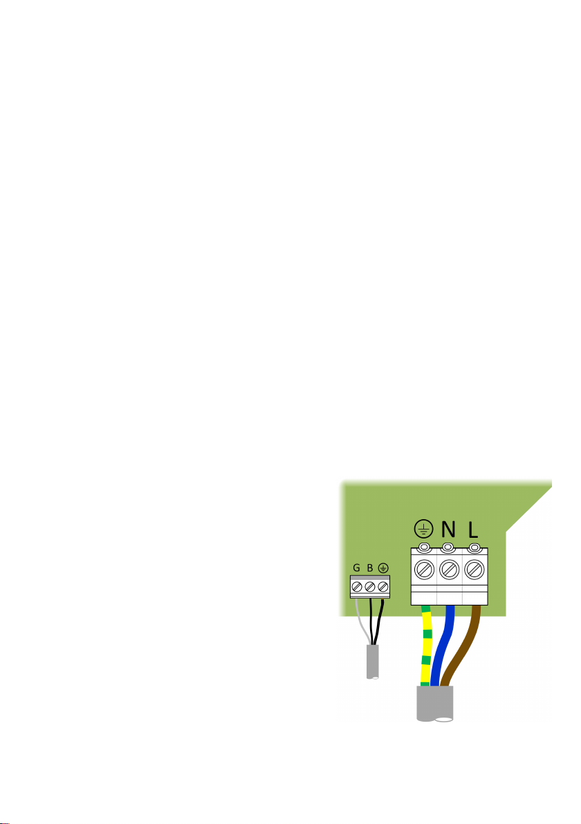
2. Wire the clamp to the VEVA unit. The measurement clamp is supplied with an 8m
cable with Grey and Black conductors. Depending on clamp version, a third shield wire
may also be provided. Install the cable then connect the conductors to the small
terminal block (Grey to G, Black to B), as shown. If provided, connect the shield wire to
the earth terminal.
If the cable needs to be extended, or if using
the data cable within a combined data and
power supply cable, shorten the clamp cable
and connect to the data cable using the
miniature junction box (supplied).
Note: To prevent interference, any
additional cable used must be either twisted
pair or shielded, twisted pair cable e.g., CAT
5 data cable. Failure to use a correct data
cable will cause distortion to measurements.
Where using a shielded data cable, the cable
shielding must be connected to the earth
terminal of the VEVA connector block. It is
good practice to protect the exposed copper
shield with a small length of sleeve.
3. Install clamp. Open the measurement clamp and position around the previously
identied supply cable, observing the correct orientation marked on the clamp. Close the
clamp around the cable and ensure that the latch is engaged.
The commissioning process will check that the clamp has been tted correctly. If the
clamp has the wrong orientation, this can be corrected automatically without needing to
change the installation using the Engineering function of the VEVA app, see page 13.
To
Meter
To Consumer unit or
connector block
(if tted)
Connect shielding to earth
if using additional shielded
cable