manuals.online logo
Brands
  1. Home
  2. •
  3. Brands
  4. •
  5. Marley
  6. •
  7. Industrial Equipment
  8. •
  9. Marley Geareducer 20 Series Setup guide

Marley Geareducer 20 Series Setup guide

– 1 –
JANUARY 1992 RM-20H
Field Repair
Instructions
●
Series 20, 20T & 20.1
STANDARD AND TYPE CC (EXTENDED FAN SHAFT)
GEAREDUCER®
M A N U A L
FIELD REPAIR–SERIES 20, 20T & 20.1 GEAREDUCERS
– 2 –
Series 20, 20T & 20.1 Cross Section
Figure 1. Gear Match Numbers and Setting Data
– 3 –
Field Repair Instructions
FOR SERIES 20, 20T & 20.1 MARLEY GEAREDUCER
STANDARD AND TYPE CC (EXTENDED FAN SHAFT)
GENERAL
Geareducers can be repaired in the field; however, major
repairs require the use of a fully equipped machine shop.
When field repair or replacement of parts is necessary, the
followingprocedureisrecommendedforthedisassemblyand
assembly of the unit. If any “O” ring, oil retainer or gasket is to
be re-used, care should be taken not to damage it during
disassembly.Partswhichcontain“O”ringsorsealsshouldnot
be jerked or twisted past a shoulder or edge. These parts are
marked with an asterisk (*) in the description below. All “O”
rings, oil retainers, and gaskets should be carefully inspected
fordamagebeforebeing reinstalled.Marley recommendsthat
new “O” rings and oil retainer be installed during a major
overhaul. Gasket is replaced by Permatex No. 2. See Figure
5, page 7.
DISASSEMBLY
Item numbers refer to Fig. 2, pages 4 and 5.
1. Remove drain plug (Item 1) and drain oil.
2. Remove outer ring of bolts (Item 2.1) in pinion cage cap
(Item 2.2) and remove pinion sub-assembly* (Item 2).
CAUTION: The thickness of this shim pack (Item 2.3) is
important in the resetting of the gears. The shim pack
should either be saved or carefully measured with a
micrometer. If the gears are to be replaced, record the
pinion setting distance that is etched on the pinion gear.
3. Remove bottom cap (Item 3).
4. Remove fan shaft disc (Item 5) and shim pack (Item 5.1)
and pull ring gear hub (Item 6).
CAUTION: The thickness of this shim pack (Item 5.1) is
important in the backlash setting of the gears. The shim
pack should either be saved or carefully measured with a
micrometer.
The gear hub may be removed by using the
fanshaftdiscand place bolts, or a hub pullercanbeused
bymakingaspecialplate;similartothefanshaftdisc,with
a clearance hole that will allow the puller to push against
the fan shaft (Item 10). Loosely attach plate to gear hub
andpullagainstplatewithhubpuller.Ametal disc should
be placed between the fan shaft and the hub puller to
protect the end of the fan shaft.
5. Remove water slinger* (Item 7).
6. Remove labyrinth ring (Item 8) and shim (Item 9).
7. Pressorpullfanshaft(Item10).Thetopbearingcup(Item
11) will be removed with the fan shaft.
8. Remove ring gear (Item 12) from ring gear hub.
PINION CAGE DISSASSEMBLY
1. Remove pinion cage cap* (Item 2.2) from pinion cage
(Item 2.4).
2. Remove “O” rings (Items 2.5 and 2.6).
3. Remove locknuts (Item 2.7) and lockwasher (Item 2.8);
then press pinion shaft (Item 2.9) out of pinion cage. This
willfree tailbearingcone (Item2.10).Ahydraulic pressor
jackisrecommendedforremovingorassemblingpressfit
parts.
4. Press oil slinger (Item 2.11) and head bearing cone (Item
2.12)fromthepinionshaft.Bearingsmustnotbeexposed
to dirt, dust or moisture.
5. Press bearing caps (Item 2.13 and 2.14) out of pinion
cage.
6. If oil retainer (Item 2.15) in pinion cage cap is worn or
damaged and is to be replaced, it can be removed with a
hammer and punch.
FAN SHAFT ASSEMBLY
1. Press or pull top bearing cone (Item 13) from end of fan
shaft.
2. Pressorpullbottombearingcone(Item14)fromfanshaft.
3. Press bottom fan shaft bearing cup (Item 15) out of case.
– 4 –
Figure 2. Exploded Cross-Section Series 20, 20T & 20.1 Geareducer
– 5 –
Figure 3. Gear Backlash Measurement
Figure 4. Bottom Cap
Early models were supplied with a
gasket between the case and bottom
cap. In place of gasket, use Permatex
"Form-A-Gasket" No. 2 as shown.
– 6 –
ASSEMBLY
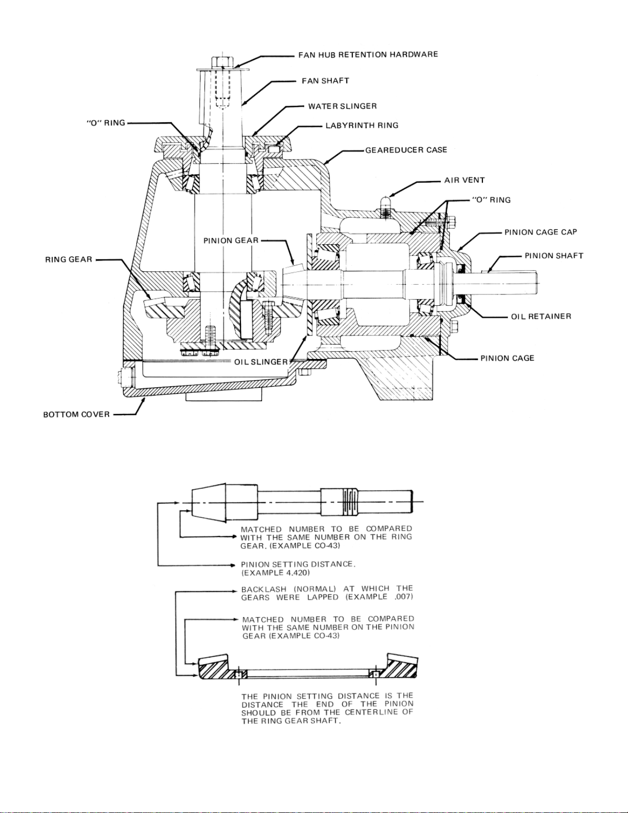
Beforeassemblinganewpiniongearinthepinioncage,check
matchnumberson pinion gear and spiral bevelringgeartobe
certain that they are a matched set. Gears are lapped in
matched sets at the factory and should not be separated.
Numbers are etched on both the pinion and ring gear as
illustrated in Fig. 1, page 2.
All parts that are to be reused should be thoroughly cleaned
with Kerosene before being reinstalled. Do not remove new
bearingsfromcartonuntilreadytouse.Washallbearings(new
or old) with Kerosene. Do not spin-dry bearings. Take each
bearingsetandrollthecupontheconetonoteanyroughness.
Replace bearing if necessary. If bearings cannot be installed
immediatelyafterwashing,lubricateandcoverthemtoprotect
against dust, moisture, etc.
If a press is not available to install bearing cones, they can be
heated as long as the temperature does not exceed 275°-
300°F. If the bearings get hotter than this, they will begin to
draw and soften. Bearings can be heated with infrared lamps
or with oil baths. If an oil bath is used, the bearing should be
supported an inch or so above the pan to prevent local
overheating.
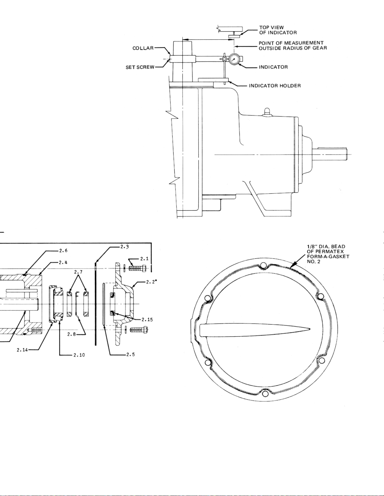
PINION CAGE SUB-ASSEMBLY
1. Place oil slinger (Item 2.11) on pinion shaft (Item 2.9).
2. Press head bearing cone (Item 2.12) on pinion shaft
making sure oil slinger and bearing are against gear.
3. Pressbearingcups(Items2.13and2.14)intopinioncage
(Item 2.4).
4. Lowerpinioncageonpinionshaft,untilheadbearingcone
and cup mate.
5. Press tail bearing cone (Item 2.10) on pinion shaft until it
mates with its bearing cup.
6. Install locknuts (Item 2.7) and lockwasher (Item 2.8).
Tighten nuts on bearing cone until 5 to 15 inch pounds of
bearing preload is obtained. Bearing preload is the resis-
tancein the bearingstoshaft rotation measuredinin./lbs.
torque required to rotate the shaft at uniform velocity.
Preload is necessary to insure the stability of the gear
engagement. Crimp the lockwasher to hold the two nuts
in place.
7. Install “O” ring (Item 2.6) in groove.
8. Installoilretainer(Item2.15)inpinioncagecap(Item2.2).
This seal is to prevent oil leaking out of the Geareducer;
therefore, the sealing lip must point inward. Clean oil
retainer seat in cap and press retainer in place. Use a
short piece of pipe with outside diameter .010 to .020 in.
Iess than the retainer outside diameter. Do not apply
hammer blows or uneven pressure directly to seal sur-
face. Be careful not to tip retainer while installing it.
Provide a sleeve to protect the seal lip as it passes over
the shaft keyway. Shim stock .010 to .015 inch thick can
be used for this sleeve as long as the lapping edge is
smoothed off and the seal is turned with the lap in the
sleeve rather than against it. A small amount of light
grease can be used to lubricate the sealing lip.
9. Position “O” ring (Item 2.5) and push cap (Item 2.2) (with
seal and sleeve) in place on shaft. Attach cap to pinion
cage and slide sleeve from cap.
10. Record the pinion setting distance that is etched on the
pinion gear.
INSTALLATION OF FAN SHAFT
1. Press bottom bearing cup (Item 15) in case.
2. Press bearing cones (Item 13 and 14) on fan shaft (Item
10).
3. Lower fan shaft into case until bearing cone mates with
bearlng cup.
4. Press top bearing cup (Item 11 ) into case.
5. Install labyrinth ring (Item 8) and adjust cap screws (Item
16) until a bearing preload of 5 to 15 inch pounds is
obtained.Measurethegapbetweenthelabyrinthringand
thecase.Makeashimpack(Item9)equaltothethickness
of this gap. Remove ring and install shim pack. Reinstall
labyrinth ring and check bearing preload. If necessary,
adjust shim gap to obtain the proper bearing preload .
INSTALLATION OF RING GEAR HUB
1. Attach ring gear (Item 12) to hub (Item 6). (Use 30 to 35
foot pounds torque on place bolts.)
2. Press ring gear hub on the fan shaft.
CAUTION: Block the end of the fan shaft while pressing
hub on shaft. Do not press against top bearing.
The
tapped hole (5/8-11NC x 1.00 deep) in the end of the fan
shaft may be used to pull the hub on. (If the tapped hole
is used, check around the hole after the hub is on to be
surethereare no raisededgesthatwouldkeep the shims
(Item 5.1 ) from seating properly against the shaft.) Stop
the bottom edge of the hub approximately .100 from the
end of the shaft.
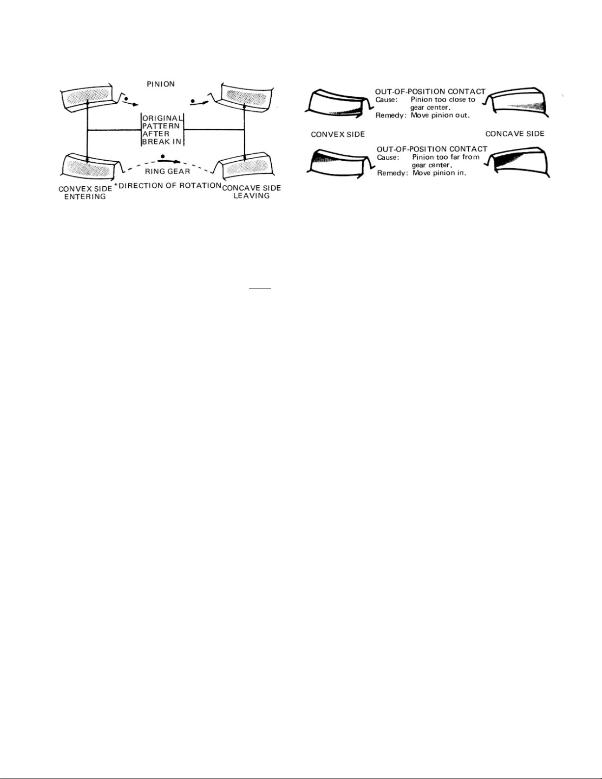
INSTALLATION OF PINION CAGE
1. The “X” marked pinion and gear teeth should be clearly
identifiedwith chalk or other markings which canbe seen
from the inspection opening or the bottom of the case.
2. Findthedifference between the pinionsettingdistanceof
the old gear and the new pinion gear and adjust the old
shimpack(Item2.3)ormakeanewshimpacktocompen-
sate for the different setting distances.
– 7 –
Correct Pinion & Gear Tooth Contact Patterns Incorrect Ring Gear Tooth Contact Pattern
Figure 5. Tooth Contact Pattern Correct and Incorrect
Example:
Pinion setting distance of old gear 2.883
Pinion settinq distance of new qear 2.878
Difference .005
Remove .005 from shim gap.
3. Install shims (Item 2.3) and pinion cage sub-assembly
(Item2). CAREMUSTBETAKENNOT TODAMAGEthe
pinion gear teeth by forcing them into the ring gear teeth.
GEAR SETTING PROCEDURE
Thepropermountingofthegear set is essential to obtain long
life and smooth operation of the gears. The pinion and ring
gears were positioned approximately in the preceding steps.
The correct gear position is determined by the gear tooth
contact pattern and by the backlash.
Withthe“X”markedtoothonthepiniongearengaged between
the two “X” marked teeth on the ring gear, check the backlash
with a dial indicator as shown in Fig. 3. Lock the pinion shaft
against rotation. The amount of movement of the fan shaft,
measured at a distance equal to the outside radius of the ring
gearisthebacklash.The backlashonallgearratiosshouldbe
between .005 and .012. With the “X” teeth engaged the
backlash should be approximately in the middle of the allow-
able range. Adjust the ring gear axially until the proper back-
lash is obtained. Check the backlash at three other points
around the ring gear to be sure the backlash is within the
specifiedlimits.Thefanshaftdiscandthestandardplacebolts
maybeusedtoadjusttheringgearineitherdirection.Afterthe
correct backlash is obtained, remove fan shaft disc and mea-
sure the distance from the end of the fan shaft with a depth
micrometer. Install a shim pack (Item 5.1) equal to this depth
and replace the disc. (Tighten the inside bolt circle before
tightening the outside bolt circle. Use 85 to 90 foot pounds
torque.)
Recheckthebacklashtomakesureitiswithintheproperlimits.
With gears adjusted to the proper backlash, blue (Prussian
blue in oil) the pinion teeth. (By using a long handled brush or
swab, the pinion teeth can be reached through the inspection
opening.) Drive the pinion by turning the fan shaft in both
directions for several revolutions. Observe the markings on
both gears on both sides of the teeth. Compare the markings
withthecontact pattern shown in Figure 5.Ifcontactpatternis
incorrect, adjust the pinion position with shims between the
pinion cage cap and Geareducer case.
Whentoothcontactiscorrect,recheckbacklash.Ifnecessary,
adjustringgeartoobtainproperbacklashandrecheckcontact
pattern. Proper contact is the more important of the two. On a
used set of gears, it may be necessary to set the gears with
slightly greater backlash in order to obtain proper tooth con-
tact.Shouldaconditionbeencounteredwherecorrectcontact
cannot be obtained, the Geareducer should be returned to
Marley’s Olathe, Kansas plant in exchange for a factory
reconditioned unit.
FINAL ASSEMBLY
1. Apply 1/8" diameter bead of Permatex No. 2 to flange of
bottom cap. Bead to be centered on flange, and to be
inside of and adjacent to bolt holes (see Figure 4).
2. Install bottom cap and tighten attaching cap screws to 25
ft./lbs. torque.
3. Install “O” ring (Item 17) in water slinger (Item 7).
4. Fillgrooves ofthelabyrinth ring(Item8)and waterslinger
(Item 7) with a lithium base grease (NLGI-2).
5. Install water slinger on fan shaft (Item 10).
6. Replace air vent and all pipe plugs.
7. Fill with lubricant selected from Table 1, page 8. Refer to
Geareducer Service Manual for complete service and
lubrication instructions.
– 8 –
LUBRICANTS FOR MARLEY GEAREDUCERS
To insure maximum performance and service life, The Marley
Cooling Tower Company recommends Marley factory ap-
provedoilsbeusedinallMarleyspiralbevelGeareducers.You
can purchase Marley approved oils through your local Marley
sales office in one-gallon and five-gallon containers.
If you must use any oil other than Marley factory approved oil,
the lubricant must not contain any additives (such as deter-
gents or EP additives) which are adversely affected by mois-
ture and could reduce the service life of the Geareducer. The
responsibility for use of oils other than Marley approved
lubricants rests with the customer/user and the lubricant
supplier.
Seasonal temperature changes may require one viscosity of
oilforsummeroperationandanotherforwinteroperation.Use
the following table as a guide.
The Mobil synthetic lubricants listed below may be used where extended service intervals are desired (up to five years).
Severe Duty/High Temperature
Above 110°F
Mobil SHC 630
Winter or Summer
32°F to 110°F
Mobil SHC 629
Table II. Air Temperature at Geareducer
Turbine-type mineral oils conforming to the viscosity requirements outlined in Table I may be used. These lubricants will provide
service life of up to six months.
Table I. Air Temperature at Geareducer
Winter
Below 32°F
SAE 20
Viscosity S.U.S.
At 100°F 230-310
(Heat Exchangers Only)
Winter or Summer
32°F to 110°F
SAE 30
Viscosity S.U.S.
At 100°F 450-610
Summer
Above 110°F
SAE 40
Viscosity S.U.S.
At 100°F 750-1000
5800 Foxridge Drive — P.O. Box 2912 — Mission, Kansas 66202
913 362-1818

This manual suits for next models

2

Other Marley Industrial Equipment manuals

Marley Air 4.0 Manual

Marley

Marley Air 4.0 Manual

Marley Geareducer 32.2 User manual

Marley

Marley Geareducer 32.2 User manual

Marley Geareducer 32.2 User manual

Marley

Marley Geareducer 32.2 User manual

Marley Clearsky F400 User manual

Marley

Marley Clearsky F400 User manual

Marley Air 4.0 Manual

Marley

Marley Air 4.0 Manual

Marley 2700-3000 Series User manual

Marley

Marley 2700-3000 Series User manual

Popular Industrial Equipment manuals by other brands

Kemper MINI-TRESOR Installation and operating instructions

Kemper

Kemper MINI-TRESOR Installation and operating instructions

Detroit Diesel MBE4000 Inspection Procedure

Detroit Diesel

Detroit Diesel MBE4000 Inspection Procedure

ABB LT 460AC operating instructions

ABB

ABB LT 460AC operating instructions

Allen-Bradley 140-KN quick start guide

Allen-Bradley

Allen-Bradley 140-KN quick start guide

Jetting MJet V3 User Guide and Safety Manual

Jetting

Jetting MJet V3 User Guide and Safety Manual

schmersal AZM201Z-CC-T-1P2PW-DU Instructions for operation

schmersal

schmersal AZM201Z-CC-T-1P2PW-DU Instructions for operation

Halfen TPA-R-05 instructions

Halfen

Halfen TPA-R-05 instructions

BWT PERMAQ PRO 2000 Installation and operating manual

BWT

BWT PERMAQ PRO 2000 Installation and operating manual

Edge Technologies Rebel 102SE manual

Edge Technologies

Edge Technologies Rebel 102SE manual

ITW Dynatec DM55 DynaDrum Technical documentation

ITW Dynatec

ITW Dynatec DM55 DynaDrum Technical documentation

Bosch KPS 003 operating instructions

Bosch

Bosch KPS 003 operating instructions

Carlisle Fluid Technologies IntelliSpray IS40 user manual

Carlisle Fluid Technologies

Carlisle Fluid Technologies IntelliSpray IS40 user manual

Tsubaki ECHT-FLEX COUPLING NES Series installation manual

Tsubaki

Tsubaki ECHT-FLEX COUPLING NES Series installation manual

ABB CAL18-11 operating instructions

ABB

ABB CAL18-11 operating instructions

Thermo Scientific HyPerforma S.U.B. TK quick start guide

Thermo Scientific

Thermo Scientific HyPerforma S.U.B. TK quick start guide

Tormach PCNC 770 Assembly manual

Tormach

Tormach PCNC 770 Assembly manual

BMT SRS:200:FA-V3 instruction manual

BMT

BMT SRS:200:FA-V3 instruction manual

Festo ELFC-KF operating instructions

Festo

Festo ELFC-KF operating instructions

manuals.online logo
manuals.online logoBrands
  • About & Mission
  • Contact us
  • Privacy Policy
  • Terms and Conditions

Copyright 2025 Manuals.Online. All Rights Reserved.