Marley Geareducer 32.2 User manual

Geareducer®
model 32.2
INSTALLATION - OPERATION - MAINTENANCE
Z0238997_C ISSUED 06/2022 READ AND UNDERSTAND THIS MANUAL PRIOR TO OPERATING OR SERVICING THIS PRODUCT
user manual

2
operation and service
Corrosion and Dry Start-Up Protection
Marley Geareducers utilize iron and steel materials, which if not
maintained correctly, may degrade. While some external corrosion
is acceptable, an internal lubrication film must be maintained at all
times to protect the working components against corrosion and
potential startup damage. The following information describes
methods of operation and preventive measures to ensure suitability
for long-term operation.
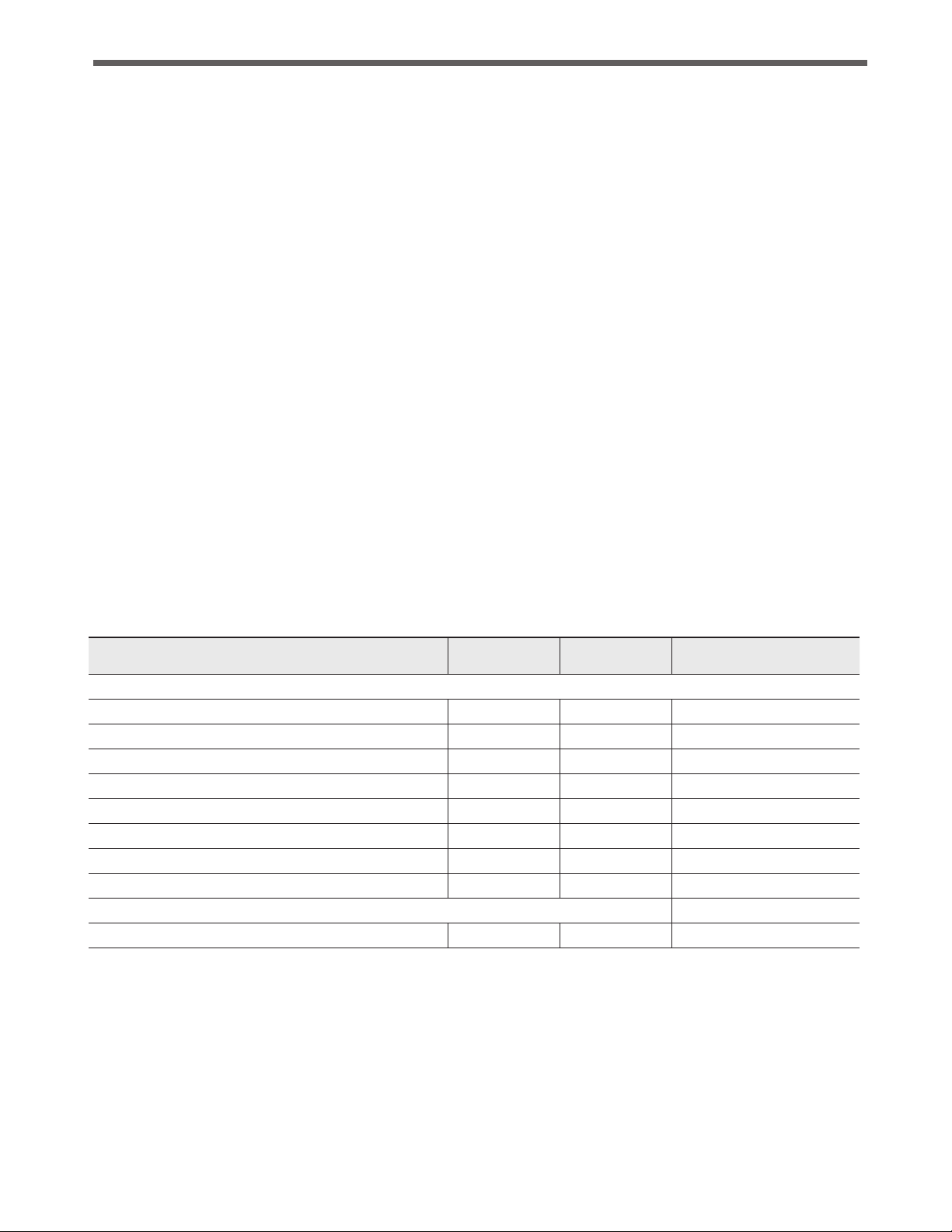
Status Definitions
Pre-Commission
Duration* = Up to 4 months after receipt.
*export shipment status duration is reduced by 1 month
This is the as-shipped condition, which contains a factory rust-
proofing coating on the interior of the unit as well as a grease
coating on the exposed shaft surfaces.
If the cooling tower is not ready for operation at the time of
status expiration, steps must be taken to place the Geareducer
into Long-Term Storage or Downtime status.
Operational
This stage is initiated upon the first motor driven sequence. The
Geareducer is now considered as being placed into regular
service and operation.
Idle
Duration = 2 to 4 weeks.
This stage is a suspension in operational status and lasts up
to two 2 weeks. The duration may be doubled by completing
a Run Cycle.
It is not recommended to extend the idle status more than once
in any given sequence.
A common application is during a temporary outage
Seasonal Shutdown
Duration = Up to 4 months after operational is suspended.
This stage may be considered an extended idle condition.
Requires additional preventive maintenance.
Long-Term Storage or Downtime
Duration = Indefinite.
Requires long-term preventive measures.
Run Cycle
Defined as full speed operation for a minimum of 30 minutes.
This recoats all internal components and surfaces with lubri-
cant and also helps to expel some moisture that may have
accumulated from daily ambient condition cycling.
As shipped, a Marley Geareducer is protected internally against
corrosion with machine enamel on un-machined parts and with
rust-proofing oil and grease on machined surfaces. These coatings
normally protect the Geareducer against corrosion for the duration
of the Pre-Commission phase. Adding normal lubricant to the
unit will dissolve the rust-proofing oil in the Geareducer sump.
Provided it is added via the filler-neck or pumped in through the
drain connection, this lubricant will not reduce the overall level
of protection however, if the unit is operated for any amount of
time, the Pre-Commission period is depleted and the unit is now
considered to be in Operational status.
Check the Geareducer exterior yearly. Touch up with paint as
required. Exposed pipe threads are coated to prevent corrosion.
Touch up coating as required.
Initial Operation
Priming
Due to lack of control over facility operational readiness, site
ambient conditions or storage practices, etc., it is recommended
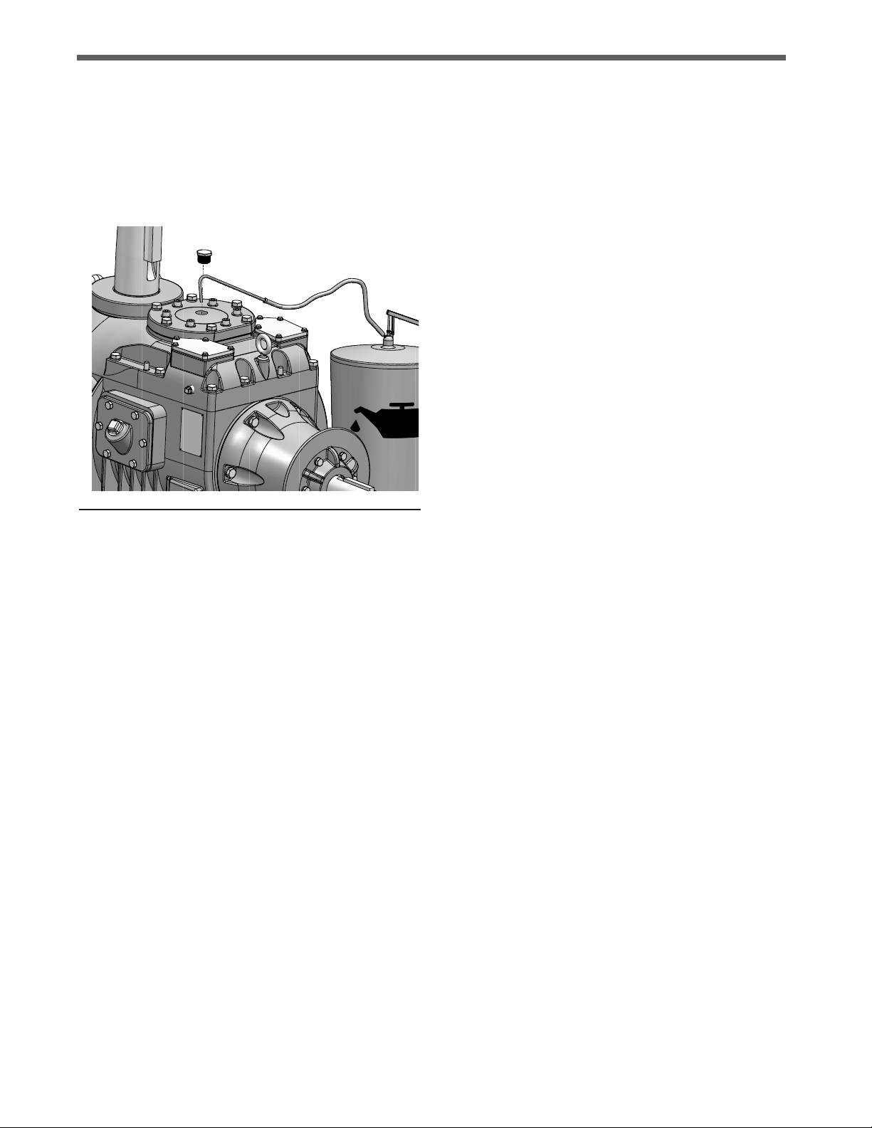
to supplement lubricant prior to initial operation. The same fill
lubricant should be poured or pumped into the port above the
interstage shaft. Remove pipe plug in center of Interstage Bear-
ing Cap to expose port. Refer to Figure 1. If additional oil is be-
ing used, an amount of 1 to 1 1/2 quarts should be used. If the
lubricant is being pumped from the sump bulk volume, at least
1 quart should be transferred. In either case, this priming step
should be performed within 5 days of initial operation. If a delay
occurs and the 5 day duration is exceeded, repeat the process.
In either case, this priming step should be performed while rotat-
ing the gear train by hand and within 5 days of initial operation.
Warning – Operating the Geareducer at an oil level other than
between the Add and Full levels may damage the unit and possibly
mating equipment. This could also escalate to a safety concern
for nearby personnel.
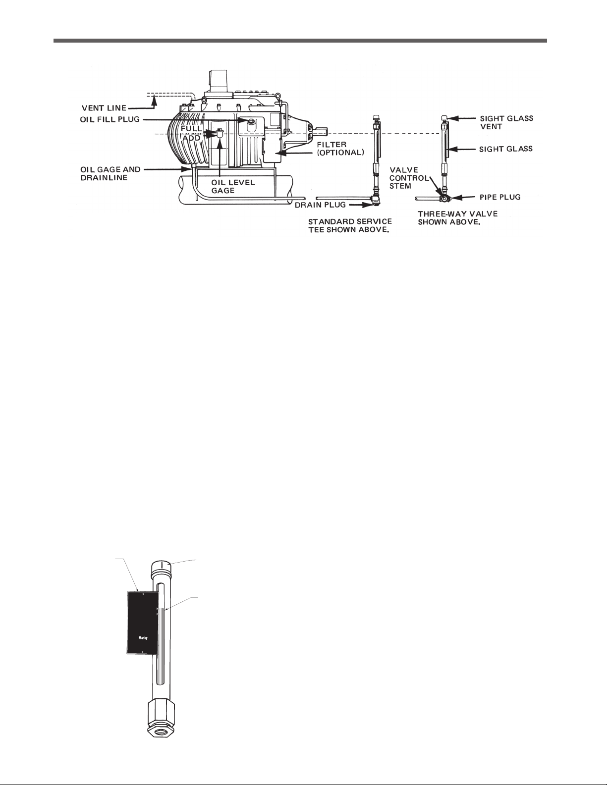
The Geareducer must be filled with oil to the Full oil level mark on
the Geareducer case before it is placed in operation. If the unit
is being taken out of Long-Term Storage or Downtime, the oil
should be drained down to the Full operating level. If drain-down
occurs within 5 days of the initial startup, the above priming se-
quence may be skipped. See Change Geareducer Oil section
for oil filling instructions.
Geareducers supplied with new cooling towers include oil for the
initial filling and in some cases, will also ship with an additional
amount required to place the unit into Long-Term Storage or
Downtime status. Normally, oil is not furnished with Geareducers
supplied as a spare or on replacement orders. Before operating
the mechanical equipment, check to be sure the oil level is at the
Full mark at the Geareducer and that the external gauge placard
Full mark corresponds with the Full level in the Geareducer. Check
oil lines to be sure there are no leaks.

3
The Geareducer vent or vent line must be checked for blockage
to prevent failure of pinion shaft oil seal—clean when necessary. Long-Term Storage or Downtime indefinite duration
If unit has been in an operational state, perform a Run Cycle
and drain the oil including volume in the oil line, if equipped. If in
storage, unit does not need to be operated.
Fabricate and install an overflow reservoir system and fill unit
entirely full of oil.
Maintenance Cycle If unit is stored outdoors, drain condensate
monthly and top off oil as necessary. If unit is stored indoors,
but not climate controlled, maintenance cycle may be extended
to 3 months. If stored in climate controlled space, cycle may be
extended to once per year.
See Marley User Manual Z0238848 “Cooling Tower Downtime
Instructions” and Marley Drawing Z0544916 “Marley Geareducer
Reservoir System” for further information.
Inspection Of Internal Parts
Remove the inspection cover plate from the side of the Geareducer
case at each oil change. Check inside of Geareducer for cleanliness
of case and internal parts. If any sludge is present, flush inside of
Geareducer and connecting oil line.
Also at this time, observe the contact pattern of the gear teeth to
see if they appear as illustrated in Detail A and B. If incorrect gear
tooth pattern should occur, refer to Marley Field Repair Manual
for Series 32.2 Geareducer.
operation and service
Figure 1 Priming Interstage Shaft
Check all gasketed joints for oil seepage. Tighten cap screws and
flange bolting if necessary.
The Geareducer must be installed level and properly aligned
with the driveshaft and motor shaft. Refer to the Driveshaft
User Manual.
It is recommended to operate the Geareducer for no less than
30 minutes in any given run sequence. It is acceptable to ignore
this when “bumping” the motor for confirmation of the correct
direction of rotation.
Seasonal Shutdown up to 4 months
At start of shutdown period, perform a Run Cycle and change the
oil. See section on Changing Geareducer Oil.
Every 2 weeks check the oil level and perform a Run Cycle.
Once each month drain any water condensation from the lowest
point of the Geareducer and its oil system. Check the oil level and
add oil if necessary. Perform a Run Cycle.
To put back into operation, drain water condensation from the
lowest point of the Geareducer and its oil system and check oil
level. Add oil if necessary.

4
Detail A Spiral Bevel Gear Tooth Pattern
Detail B Helical Gear Tooth Pattern
operation and service

5
Changing Geareducer Oil
Drain the Geareducer oil by removing the drain plug. See
Figure 2 for location. If equipped with an external dipstick/oil
level gauge, remove the drain plug at that location, and drain the
entire system.
When using synthetic oil with extended service intervals remove a
sample for lab analysis and look for evidence of foreign material,
such as water, metal shavings or sludge. If you find unacceptable
condensation or sludge, flush the Geareducer with mineral oil
before refilling.
The horizontal part of the oil line must be level or slightly lower at
the oil level gauge than at the Geareducer. The oil capacity of the
32.2 Series Geareducer: 9 gallons (34 liters)
The oil level gauge line requires approximately one additional
gallon of oil. Refer to back cover for suggested lubricants. If the
Geareducer is equipped with an external dipstick/oil level gauge
an additional 3 to 4 quarts of oil will be required. Be certain that
the vent on the Geareducer (and external dipstick/oil level gauge,
if present) is not plugged. Verify that the gauge/drain line is full
and that there aren’t any leaks at the connections.
Figure 2 Oil Gauge and Drain Line (Series 36 Geareducer is illustrated)
operation and service
Fill the Geareducer and oil line system with oil, using one of the
following procedures:
Recommended procedure:
1. Install oil at the opening at the Geareducer inspection cover.
Full is the center of the sight glass. If oil is not visable in the
sight glass then oil needs to be added . See Figures 3 and 4.
Install plug.
2. Start the fan drive and run for one minute.
3. Stop the fan drive. Allow ten minutes for oil level to stabilize
and recheck oil level at the Geareducer.
4. If necessary, repeat steps 2 and 3 until stabilized oil level is at
the proper level.
5. Check gauge placard location. Full mark on the placard must
be at the same elevation as the Full mark at the Geareducer.
Alternate procedure:
The cooling tower has an external oil gauge and drain line equipped
with a three-way valve below the oil level gauge. See Figure 3.
1. Remove pipe plug. Turn valve control stem clockwise to open
drain.
2. With Geareducer drained, the three-way valve turned clockwise,
and the pipe plug removed, connect fill source (usually a hose
to a pump, to the three-way valve).
Pump oil through the hose. Check oil level occasionally by
turning the valve control stem counterclockwise and allowing
the oil level in the sight glass to stabilize.
Continue filling until full level mark is reached.
3. With the oil level at the full mark turn the valve control stem
counterclockwise to close the drain and open the valve to the
sight glass. Remove the oil filling line and reinstall pipe plug in
the three-way valve.
VENT
OIL LEVEL
GAUGE
OIL LEVEL
PLACARD
FULL
ADD
OIL
NOTICE
CHECK OIL LEVEL TEN
MINUTES AFTER
FAN STOPS ROTATING
FILL AT GEAREDUCER
REFER TO SERVICE MANUAL
FOR OIL CHANGE AND
MAINTENANCE RECOMMENDATIONS
SPX COOLING TECHNOLOGIES
OVERLAND PARK, KS USA
92-110A
Figure 3 Sight glass gauge assembly

6
scheduled maintenance
Maintenance Service Monthly Semi-annually Seasonal Startup or Annually
Geareducer Drive:
Inspect and tighten all fasteners including oil plug x x
Check for and repair oil leaks x x x
Check oil level x R x
Change oil R R
Make sure vent is open x x
Check driveshaft alignment x
Inspect and tighten driveshaft fasteners x
Check driveshaft bushing / flex elements for unusual wear x
Lube Lines (if equipped)
Check for oil leaks in hoses and fittings x R x
R– Refer to instructions within this manual
Note: It is recommended at least weekly, that the general operation and condition be observed. Pay particular attention to any changes
in sound or vibration that may signify a need for closer inspection.
Warning—Make certain that mechanical equipment is inoperable
during periods of maintenance—or during any situation of possible
endangerment to personnel. If your electrical system contains
a disconnect switch, lock it out until the period of exposure to
injury is over.
Monthly—Check Geareducer oil level. Shut down the unit and
allow 5 minutes for the oil level to stabilize. Add oil if required,
noting the addition in your maintenance log. If equipped with an
external dipstick/oil level gauge, small quantities of oil can be
added at that location.
Semi-annually—If using turbine-type mineral oil, change oil—see
Changing Geareducer Oil for instructions. Check that all the
assembly bolts and cap screws are tight, that oil plugs and pipe
connections are in place and free from leaks, and that the vent on
the Geareducer (and external dipstick/oil level gauge, if present) is
clear—a clogged vent can lead to oil leaks. Intermittent operation
and extended periods of downtime can cause condensation of
water in the oil. If using synthetic Marley Gearlube, the oil condition
must be inspected every six months—see Changing Geareducer
Oil for maximizing service life.
Annually—Check mechanical equipment anchor bolts, drive shaft
coupling bolts, and coupling set screws. Tighten as required. Check
Geareducer exterioryearly and touch up with epoxy paint if required.
Coat all exposed threads at pipe joints to prevent corrosion.
Every 5 Years—If using synthetic Marley Gearlube, change oil.
To maintain five-year change intervals, use only synthetic Marley
Gearlube. It is recommended to monitor the oil condition every
six months throughout the five-year period per the instructions in
Changing Geareducer Oil.

7
repair and lubricants
Table 1 Oil viscosity
Repair and Overhaul
If your Geareducer ever needs replacement or repair, SPX Cooling
Technologies recommends returning the unit to a Marley factory
service center. Contact your Marley sales representative to discuss
a course of action. The Marley Order Number on your cooling
tower will be required if the Geareducer is shipped back to the
factory for repair. Obtain a “Customer Return Material” tag from
the Marley sales representative in you area. To find your Marley
sales representative call 913 664 7400 or check the internet at
spxcooling.com.
Major repairs require the use of a fully equipped machine shop.
If you decide to repair or overhaul your Geareducer, refer to the
Field Repair Section and Geareducer Parts List.
Suggested Lubricants
The following list of lubricants in Table 1 is provided as reference
only. These products have been recommended by their respective
manufacturers as acceptable for use in a Marley spiral bevel and/
or helical Geareducer for cooling tower applications. This list is
not an attempt to include all the lubricants that may be satisfac-
tory. If lubricants other than those listed are used they must not
contain any additives—such as detergents or EP additives—which
are adversely affected by moisture and could reduce the service
life of the Geareducer. Suitability of lubricants used other than
those listed rests with the customer/owner and lubricant supplier.
Winter or Summer Severe Duty/High Temperature
Air Temperature at Geareducer
Below 110°F (43°C) Above 110°F (43°C)
ISO 150 ISO 220

Z0238997_C (M92-1436B) | ISSUED 06/2022
COPYRIGHT © 2022 SPX TECHNOLOGIES
In the interest of technological progress, all products are subject to design
and/or material change without notice.
Geareducer 32.2
USER MANUAL
SPX COOLING TECH, LLC
7401 WEST 129 STREET
OVERLAND PARK, KS 66213 USA
spxcooling.com
Table of contents
Other Marley Industrial Equipment manuals
Popular Industrial Equipment manuals by other brands

ABB
ABB ACx580-01-02A6-4 Service instructions

Dorner
Dorner 2200 series Installation, maintenance & parts manual

Vega
Vega VEGASON 64 operating instructions

Ecotech Italia
Ecotech Italia DW45 Manual for use and maintenance

Record Power
Record Power SC3 Original instructions

Stahl
Stahl ISpac 9147 Series operating instructions

Turbovex
Turbovex TX 3100A User manual and installation guide

Komatsu Utility
Komatsu Utility D155AX-5 Operation & maintenance manual

schmersal
schmersal TZM Series operating instructions

Rikon Power Tools
Rikon Power Tools 29-201 quick start guide

Bticino
Bticino BT-M7M024 manual

REGATRON
REGATRON TopCon TC.LAE Preliminary manual