Martel LC-110 User manual

LC-110/H
Reference Manual
www.GlobalTestSupply.com
Find Quality Products Online at: sales@GlobalTestSupply.com

1. Introduction ........................................1
1.1 Customer Service ................................................1
1.2 Standard Equipment ..............................................2
1.3 Safety information ................................................2
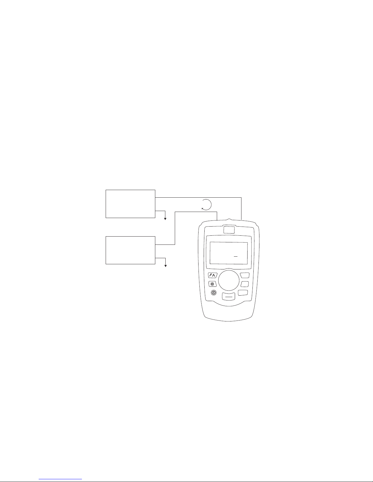
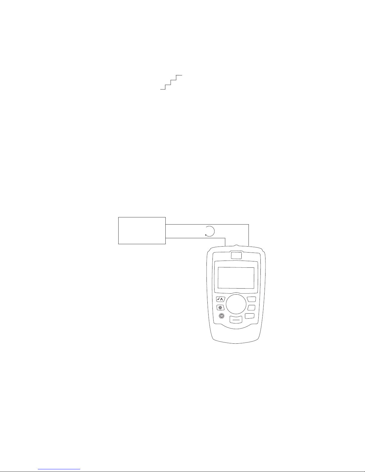
2. Calibrator Interface and Operation .....................5
2.1 Milliamp Source .................................................6
2.2 Milliamp Simulate.................................................7
2.3 Milliamp Measure without 24V power .................................8
2.4 Milliamp Measure with 24V power ...................................9
2.5 Volts Measure ...................................................9
3. Main Menu ........................................10
4. Calibrator Setup Menu...............................11
4.1 Setting Auto Ramp Time ..........................................11
4.2 Setting Auto Step Time ...........................................12
4.3 Enabling Valve Test ..............................................12
4.4 Enabling the HART Resistor........................................13
4.5 Selecting mA Span ..............................................13
4.6 Contrast Adjustment. . . . . . . . . . . . . . . . . . . . . . . . . . . . . . . . . . . . . . . . . . . . . . 13
4.7 Configuring Auto Shutdown .......................................14
4.8 HART Write Enable...............................................14
5. Advanced Features..................................15
5.1 Step and Ramp Operation.........................................15
5.2 Valve Test ......................................................16
5.3 HART 250ΩResistor .............................................16
6. HART Device Communications ........................17
6.1. HART Connection Diagrams.......................................17
6.2 Communications Setup and Selection ...............................19
6.3 Connecting to a HART Device......................................21
6.4 Disconnect.....................................................23
6.5 Function Select Menu ............................................23
6.6 Display Setup & Data.............................................23
6.7 Modify Setup ...................................................24
6.8 Trim, Set, & Zero Menu ...........................................28
6.9 Device Diagnostic ...............................................32
6.10 Data Log & Config Log ..........................................33
6.11 HART Modem Simulation.........................................38
6.12 Error Displays..................................................39
7. Maintenance .......................................45
7.1 Replacing Batteries ..............................................45
7.2 Cleaning the Unit ................................................45
7.3 Fuse Protection .................................................45
8. Specifications .....................................46
9. Warranty ..........................................46
www.GlobalTestSupply.com
Find Quality Products Online at: sales@GlobalTestSupply.com

1
Introduction
The Martel LC-110 and LC-110H are mA (loop) calibrators designed
to be simple to use and to offer the highest accuracy of any loop
calibrator in their class. The LC-110H differs from the standard
LC-110 in that it incorporates HART communications and supports a
select subset of the HART universal and common practice
commands. This unique feature allows the LC-110H to be used as
both a loop calibrator and basic function communicator.
The calibrator supports the following functions:
•Currentmeasurementandsourcing,includingselectable24V
supply
•Voltagemeasurement
•Valvetestcapability
•SelectableHART250Ωloop resistor
•Outputstepandramp
The calibrator has the following features:
•Largeeasytoreaddisplayformeasurementsanddataentry
•Digitalknobwithselectabledecadecontrolforquickandeasy
data entry
•Interactivemenus
•Inputandoutputjacksprotectedbyselfresettingfuses
providingprotectionto240VAC
Inthecommunicatormodetheuserisabletoreadbasicdevice
information,performdiagnostictests,andtrimthecalibrationonmost
HARTenabledtransmitters.Inthepastthiscouldonlybedonewitha
dedicated communicator.
TheLC-110HcanalsobeusedasaHARTmodem,allowingPChost
applications to perform more sophisticated diagnostics and setup.
HARTformatcommandsfromthehostarepassedtothetransmitter,
andresponsesarepassedback.
www.GlobalTestSupply.com
Find Quality Products Online at: sales@GlobalTestSupply.com

2
1.2 Standard Equipment
Checktoseeifyourcalibratoriscomplete.Itshouldinclude:
•Calibrator
•6xAAAbatteries(installed)
•Testleads
- The LC-110 is supplied with one set of leads with alligator
clips installed
-TheLC-110Hissuppliedwithtwosetsoftests.Oneset
with alligator clips and the other set with mini-grabber
style ends
•Owner’sManual
•NISTCertificate
1.3 Safety information
Symbols Used
ThefollowingtableliststheInternationalElectricalSymbols.Someor
all of these symbols may be used on the instrument or in this
manual.
SymbolDescription
AC (Alternating Current)
AC-DC
Battery
CEComplieswithEuropeanUnionDirectives
DC
DoubleInsulated
ElectricShock
Fuse
www.GlobalTestSupply.com
Find Quality Products Online at: sales@GlobalTestSupply.com

3
PEGround
HotSurface(BurnHazard)
ReadtheUser’sManual(ImportantInformation)
Off
On
CanadianStandardsAssociation
The following definitions apply to the terms “Warning” and “Caution”.
•“Warning”identifiesconditionsandactionsthatmayposehazards
to the user.
•“Caution”identifiesconditionsandactionsthatmaydamagethe
instrument being used.
Usethecalibratoronlyasspecifiedinthismanual,otherwiseinjury
and damage to the calibrator may occur.
Warning
To avoid possible electric shock or personal injury:
•Donotapplymorethantheratedvoltage.Seespecificationsfor
supported ranges.
•Followallequipmentsafetyprocedures.
•Nevertouchtheprobetoavoltagesourcewhenthetestleadsare
plugged into the current terminals.
•Donotusethecalibratorifitisdamaged.Beforeyouusethe
calibrator,inspectthecase.Lookforcracksormissingplastic.Pay
particular attention to the insulation surrounding the connectors.
•Selecttheproperfunctionandrangeforyourmeasurement.
•Makesurethebatterycoverisclosedandlatchedbeforeyou
operate the calibrator.
•Removetestleadsfromthecalibratorbeforeyouopenthebattery
door.
www.GlobalTestSupply.com
Find Quality Products Online at: sales@GlobalTestSupply.com

4
•Inspectthetestleadsfordamagedinsulationorexposedmetal.
Checktestleadscontinuity.Replacedamagedtestleadsbefore
you use the calibrator.
•Whenusingtheprobes,keepyourfingersawayfromtheprobe
contacts. Keep your fingers behind the finger guards on the
probes.
•Connectthecommontestleadbeforeyouconnectthelivetest
lead.Whenyoudisconnecttestleads,disconnectthelivetestlead
first.
•Donotusethecalibratorifitoperatesabnormally.Protectionmay
beimpaired.Whenindoubt,havethecalibratorserviced.
•Donotoperatethecalibratoraroundexplosivegas,vapor,ordust.
•Disconnecttestleadsbeforechangingtoanothermeasureor
source function.
•Whenservicingthecalibrator,useonlyspecifiedreplacementparts.
•Toavoidfalsereadings,whichcouldleadtopossibleelectricshock
orpersonalinjury,replacethebatteryassoonasthebattery
indicator appears.
•Toavoidaviolentreleaseofpressureinapressurizedsystem,shut
off the valve and slowly bleed off the pressure before you attach
the pressure module to the pressure line.
Caution
To avoid possible damage to calibrator or to equipment under test:
•Usetheproperjacks,function,andrangeforyourmeasurementor
sourcing application.
www.GlobalTestSupply.com
Find Quality Products Online at: sales@GlobalTestSupply.com

5
2. Calibrator Interface and Operation
MARTEL ELECTRONICS
LC-110H Precision Loop
Calibrator w/HART™
100%
25%
0%
MENU
EXIT
Source 0.00%
4.000mA
Simultaneous % Display
4mA = 0.00%
20mA = 100.00%
Cursor
100% Key: Sets Output to 20mA
25% Key: Steps 4, 8, 12, 16, 20mA
0% Key: Sets Output to 4mA
Digital Knob Sets Output Value
Press to Move Cursor
Menu
Press to Enter Setup Menu
Press Again to Exit
Step / Ramp Enable
Backlight
On / Off
Mode
Figure 1
Figure1istypicalofthemaindisplayforalloperatingmodes.It
shows the present measurement or output value. The individual
operating modes are described below.
UsetheMENU/EXITkeytodisplaythemainmenudescribedin
section3toselecttheprimaryoperatingmodeofthecalibrator,to
accessthecalibratorsetupfunctions,ortoenterHARTmode.
Inoutputmode:
•Presstheknobtomovethedecadecursor.
•Rotatetheknobtoincrementordecrementtheoutputinsteps
indicated by the selected decade.
•Usethe3percentkeystodirectlysettheoutputtopreset
values.
•Usethestep/rampkeytoselectandstoptheseadvanced
modeswhicharedescribedinsection5.1.
www.GlobalTestSupply.com
Find Quality Products Online at: sales@GlobalTestSupply.com

6
2.1 Milliamp Source
InthemASourcemodethecalibratoroutputsasignalfrom0to
24mAintoaloadofupto1000ohms(750ohmsiftheinternalHART
resistor is switched on).
Figure2showsthemaindisplayandtypicalconnectionsforthis
mode.
MARTEL ELECTRONICS
LC-110H Precision Loop
Calibrator w/HART™
100%
25%
0%
MENU
EXIT
Source 0.00%
4.000mA
4-20mA INPUT DEVICE
RECORDER/INDICATOR
SCADA SYSTEM ETC.
(+)
(–)
4 to 20mA
Figure 2
•Presstheknobtomovethedecadecursor.
•Rotatetheknobtoincrementordecrementtheoutputinsteps
indicated by the selected decade.
•Usethe3percentkeystodirectlysettheoutputtopresetvalues.
•Usethestep/rampkeytoselectandstoptheseadvancedmodes
whicharedescribedinsection5.1.Whenautomaticsteporramp
is active one of the following is shown in the lower left corner:
Automatic step:
Automatic ramp: ∧
www.GlobalTestSupply.com
Find Quality Products Online at: sales@GlobalTestSupply.com

7
•PressMENU/EXITtoenterthemainmenudescribedinsection3.
•Thetext‘ValveTest’isshowninthelowercenterwhenthevalve
testfunctionhasbeenenabledontheSetupMenu,section4.3.
Valvetestisdescribedinmoredetailinsection5.2.
•Thetext‘250Ω’textisshowninthelowerrightcornerwhenthe
HARTresistorhasbeenenabledontheSetupMenu,section4.4.
2.2 Milliamp Simulate
InthemASimulatemodethecalibratorfunctionslikea2-wire
transmitterbycontrollingtheloopcurrentfromanexternalpower
supply. This function is a great way to test a loop with the transmitter
removed.
Figure3showsthemaindisplayandtypicalconnectionsforthis
mode.
MARTEL ELECTRONICS
LC-110H Precision Loop
Calibrator w/HART™
100%
25%
0%
MENU
EXIT
Simulate 0.00%
4.000mA
POWER SUPPLY
30 VDC MAX
(+)
(–)
4 to 20mA
4-20mA
INPUT DEVICE
(+)
(–)
Figure 3
•Presstheknobtomovethedecadecursor.
•Rotatetheknobtoincrementordecrementtheoutputinsteps
indicated by the selected decade.
•Usethe3percentkeystodirectlysettheoutputtopresetvalues.
•Usethestep/rampkeytoselectandstoptheseadvancedmodes
whicharedescribedinsection5.1.Whenautomaticsteporramp
is active one of the following is shown in the lower left corner:
www.GlobalTestSupply.com
Find Quality Products Online at: sales@GlobalTestSupply.com

8
Automatic step:
Automatic ramp: ∧
•PressMENU/EXITtoenterthemainmenudescribedinsection3.
•Thetext‘ValveTest’isshowninthelowercenterwhenthevalve
testfunctionhasbeenenabledontheSetupMenu,section4.3.
Valvetestisdescribedinmoredetailinsection5.2.
•Thetext‘250Ω’textisshowninthelowerrightcornerwhenthe
HARTresistorhasbeenenabledontheSetupMenu,section4.4.
2.3 Milliamp Measure without 24V power
InthemAMeasuremode,thecalibratordisplaystheloopcurrent.
Figure4showsthemaindisplayandtypicalconnectionsforthis
mode.
MARTEL ELECTRONICS
LC-110H Precision Loop
Calibrator w/HART™
100%
25%
0%
MENU
EXIT
Measure 0.00%
4.000mA
4-20mA
OUTPUT DEVICE
(+)
(–)
4 to 20mA
Figure 4
•PressMENU/EXITtoenterthemainmenudescribedinsection3.
•Thetext‘250Ω’textisshowninthelowerrightcornerwhenthe
HARTresistorhasbeenenabledontheSetupMenu,section4.4.
www.GlobalTestSupply.com
Find Quality Products Online at: sales@GlobalTestSupply.com

9
2.4 Milliamp Measure with 24V power
InthemAMeasurewith24Vmode,thecalibratoroutputs24VDC
while displaying the loop current. The mode is useful for powering a
transmitter without the need for a separate power supply.
Figure5showsthemaindisplayandtypicalconnectionsforthis
mode.
MARTEL ELECTRONICS
LC-110H Precision Loop
Calibrator w/HART™
100%
25%
0%
MENU
EXIT
Measure 24V 0.00%
4.000mA
Figure 5
•PressMENU/EXITtoenterthemainmenudescribedinsection3.
•Thetext‘250Ω’textisshowninthelowerrightcornerwhenthe
HARTresistorhasbeenenabledontheSetupMenu,section4.4.
2.5 Volts Measure
IntheVoltsMeasuremode,thecalibratordisplaystheloopvoltage.
Figure6showsthemaindisplayandtypicalconnectionsforthis
mode.
•PressMENU/EXITtoenterthemainmenudescribedinsection3.
www.GlobalTestSupply.com
Find Quality Products Online at: sales@GlobalTestSupply.com

10
MARTEL ELECTRONICS
LC-110H Precision Loop
Calibrator w/HART™
100%
25%
0%
MENU
EXIT
Measure
10.000V
VOLTAGE
OUTPUT DEVICE
(+)
(–)
Figure 6
3. Main Menu
The Main Menu is used to select the primary operating mode of the
calibrator,toaccessthecalibratorsetupfunctions,andtoenterHART
mode.
mASource
mASimulate
mA Measure
mAMeasurewith24V
VoltsMeasure
CalibratorSetupMenu
HART Comm. Menu
Rotatetheknobtoselectanactionbymovingthereversevideo
highlightupanddown.Presstheknobtoperformtheselected
action.PressMENU/EXITtoreturntothemaindisplaywithout
performing an action.
The first five actions change the operating mode accordingly and
returntothemaindisplaydescribedinsection2.
The“CalibratorSetupMenu”actionisdescribedinsection4.
The “HART Comm. Menu” action is described in section 6. The
‘HART’menuitemonlyappearsontheLC-110Hdevice.
www.GlobalTestSupply.com
Find Quality Products Online at: sales@GlobalTestSupply.com

11
4. Calibrator Setup Menu
The calibrator setup menu consists of two screens. The second
screenisreachedbyselecting‘OtherParameters’onthefirstscreen.
Auto Ramp Time
AutoStepTime
ValveTest
HART250ΩResistor
OtherParameters
mASpan
Contrast
AutoShutdownTime
HARTWriteEnable
Rotatetheknobtoselectanactionbymovingthereversevideo
highlightupanddown.Presstheknobtoperformtheselected
action.PressMENU/EXITtoreturntothemaindisplaywithout
performing an action.
Note:The‘HARTWriteEnable’menuitemonlyappearsonthe
LC-110H device.
4.1 Setting Auto Ramp Time
Auto Ramp Time
10SEC.
Press&holdtoSave
This function sets the full scale ramp time for the mA ramp feature
describedinmoredetailinsection5.1.Thevaluecanbesetfrom5
to 300 seconds.
Rotatetheknobtoadjustthevalue.Pressandholdtheknobtosave
it.PressMENU/EXITtorestorethepreviousvalueandreturntothe
main display.
www.GlobalTestSupply.com
Find Quality Products Online at: sales@GlobalTestSupply.com

12
4.2 Setting Auto Step Time
Auto Step Time
10SEC.
Press&holdtoSave
ThisfunctionsetsthestepintervaltimeforthemAAutoStepfeature
describedinmoredetailinsection5.1.Thevaluecanbesetfrom5
to 300 seconds.
Rotatetheknobtoadjustthevalue.Pressandholdtheknobtosave
it.PressMENU/EXITtorestorethepreviousvalueandreturntothe
main display.
4.3 Enabling Valve Test
Valve Test Enable
OFFON
This function enables and disables the valve test feature described in
moredetailinsection5.2.
Rotatetheknobtomovethereversevideohighlighttothedesired
selection.Presstheknobtosavethehighlightedselection.Press
MENU/EXITtorestorethepreviousselectionandreturntothemain
display.
www.GlobalTestSupply.com
Find Quality Products Online at: sales@GlobalTestSupply.com

13
4.4 Enabling the HART Resistor
HART Resistor Enable
OFFON
This function enables and disables the HART resistor described in
moredetailinsection5.3.
Rotatetheknobtomovethereversevideohighlighttothedesired
selection.Presstheknobtosavethehighlightedselection.Press
MENU/EXITtorestorethepreviousselectionandreturntothemain
display.
4.5 Selecting mA Span
mASpanSelection
4to20mA
0to20mA
This function selects the mA span used to calculate the percent of
spanfieldonthemaindisplay,andtosetthevalueusedbythe0%
key.
Rotatetheknobtomovethereversevideohighlighttothedesired
selection.Presstheknobtosavethehighlightedselection.Press
MENU/EXITtorestorethepreviousselectionandreturntothemain
display.
4.6 Contrast Adjustment
Contrast
Samplenormalvideo
Samplereversevideo
This function sets the display contrast.
Rotatetheknobtoadjustthecontrast.Therangeofvaluesisshown
bythebargraph,withhighercontrastshownbyalongerbar.The
samplenormalandreversevideotextlinesallowevaluationofboth
www.GlobalTestSupply.com
Find Quality Products Online at: sales@GlobalTestSupply.com

14
textmodes.Presstheknobtosavethecontrastvalue.PressMENU/
EXITtorestorethepreviousselectionandreturntothemaindisplay.
4.7 Configuring Auto Shutdown
Auto Shutdown Time
10MIN.
This function sets or disables the time before the unit automatically
shutsdownifthekeypadisnotused.Thevaluecanbesetto
‘Disabled’,orfrom1to30minutes.
Rotatetheknobtoadjustthevalue.Pressandholdtheknobtosave
it.PressMENU/EXITtorestorethepreviousvalueandreturntothe
main display.
4.8 HART Write Enable
ThissettingisavailableonlyontheLC-110H.Itprotectsallfunctions
ontheModifySetupmenu,andtheDeviceDiagnostic,Trim4mA,
Trim20mA,SetFixedOutput,andPVZerofunctions.Thedefault
settingis“ON”,butmaybeturnedoffiftheuserwantstoprotect
againstunauthorizeduse.
HART Write Enable
OFFON
Rotatetheknobtomovethereversevideohighlighttothedesired
selection.Presstheknobtosavethehighlightedselection.Press
MENU/EXITtorestorethepreviousselectionandreturntothemain
display.
Beforethesettingischanged,apasswordisrequiredtoacceptit.
Thepasswordissetto617atthefactory.Enterthepasswordonthe
following display. The range of values that can be set is 000 to 999.
www.GlobalTestSupply.com
Find Quality Products Online at: sales@GlobalTestSupply.com

15
Password
000
Press&holdtoSave
Presstheknobtomovethedecadecursor.Rotatetheknobtoadjust
thevalueinstepsindicatedbythedecadeselected.Pressandhold
theknobtosavethewriteenablesetting.PressMENU/EXITto
restore the previous HART enable selection and return to the main
display.
The write enable setting is saved only when the correct password is
entered.Otherwiseanerrormessageisdisplayed.
5. Advanced Features
The calibrator has several advanced features that are available
throughtheCalibratorSetupMenus.Howthefeaturesareenabled
and what they do is described below.
5.1 Step and Ramp Operation
The calibrator has several unique features that are helpful aids when
doing milliamp calibrations.
Thepercentkeysallowtheusertosetthemilliampoutputto0%of
span,100%ofspan,orstepitby25%ofspan.
The“Step/Ramp”keyallowshandsfreeoperationbyautomatically
steppingorrampingthemilliampoutputfrom0%to100%andback
continuously.
The100%valueisalways20mA,butthe0%valuemaybe0mAor4
mAdependingonthemAspansettingdescribedinsection4.5.The
25%stepsizeiseither5mAor4mAaccordingly.
5.1.1 Manual Stepping
1. Usethemainmenutosetthecalibratortosourceorsimulate
current.
2. Pressthe“0%”keytosettheoutputto0%ofspan.
3. Pressthe“100%”keytosettheoutputto100%ofspan.
4. Pressthe“25%”keytosteptheoutputin25%ofspan
increments,from0%ofspanto100%ofspanandback.
www.GlobalTestSupply.com
Find Quality Products Online at: sales@GlobalTestSupply.com

16
5.1.2 Automatic Stepping and Ramping
1. Usethemainmenutosetthecalibratortosourceorsimulate
current.
2. ThecalibratorhasseparateAutorampandsteptimes.Usethe
menu system to set the ramp or step time as described in
section4.1or4.2.
3. Pressthe“Step/Ramp”keyoncetocontinuallysteptheoutput
from0%ofspanto100%ofspanandbackinincrementsof25%
of span at the specified interval.
Pressthe“Step/Ramp”oncemoretogotoautoramp.
Pressoneofthepercentkeys,orthe“Step/Ramp”twicemore,to
turn off the auto step and ramp.
4. Pressthe“Step/Ramp”keytwicetocontinuallyramptheoutput
from0%ofspanto100%ofspanoverthespecifiedinterval,and
thenbackoverthespecifiedinterval.
Pressoneofthepercentkeys,orthe“Step/Ramp”oncemore,to
turn off the auto step and ramp.
5.2 Valve Test
The calibrator has a valve test mode for verifying proper operation of
valves.Invalvetesttheusercansteptheoutputtothefollowing
values:3.8mA,4.0mA,4.2mA,8.0mA,12.0mA,16.0mA,19.8mA,
20.0mA,20.2mA,andback.
The valve test mA values are not affected by the mA span setting
describedinsection4.5
1. Usethemainmenutosetthecalibratortosourceorsimulate
current.
2. Ifvalvetestisnotenabled,usethemenusystemtoenableitas
describedinsection4.3.
3. Pressthe“Step/Ramp”keyorthe“25%”keytosteptheoutput
to verify the proper valve operation.
4. Usethemenusystemtodisablevalvetestwhendone.
5.3 HART 250ΩResistor
Thecalibratorhastheabilitytoinserta250Ωresistor in series with
the power supply in order to facilitate the use of a HART
communicator. The HART resistor is enabled through the menu
systemasdescribedinsection4.4.
www.GlobalTestSupply.com
Find Quality Products Online at: sales@GlobalTestSupply.com

17
6. HART Device Communications
The HART functions are only available in the LC-110H.
Auto shutdown is disabled on entry to the HART Menus and is
restoredtoitspreviousstateuponexitfromtheHARTmenus.
Loopcurrenttrimissupportedfortransmitterdevices,butisnot
supported for actuator devices.
AllfunctionsontheModifySetupmenu,andthedevicediagnostic,
trim4mA,trim20mA,fixedoutput,andPVzerofunctionsmaybe
disabledusingthe‘HARTWriteEnable’selectionontheCalibrator
SetupMenu,describedinsection4.8.Ifanyofthesefunctionsare
required,theymustbeenabledbeforeenteringtheHARTmenus.
6.1. HART Connection Diagrams
6.1.1 In Circuit, External Loop Power
In“mAMeasure”modetheLC-110Hisincircuitandlooppoweris
suppliedexternallyasshownbelow.
24V
SUPPLY
(+)
(–)
4 to 20mA
MARTEL ELECTRONICS
LC-110H Precision Loop
Calibrator w/HART™
100%
25%
0%
MENU
EXIT
Measure 0.00%
4.000mA
250Ω
Note:Inthissituationthe250ΩHARTresistorisenabled.Ifyourloop
alreadyhas250Ω,donotenabletheHARTresistor.
www.GlobalTestSupply.com
Find Quality Products Online at: sales@GlobalTestSupply.com

18
6.1.2 In Circuit, LC-110H Loop Power
In“mAMeasurewith24V”modetheLC-110Hisincircuitandthe
loop power is supplied by the LC-110H as shown below.
(+) (–)
MARTEL ELECTRONICS
LC-110H Precision Loop
Calibrator w/HART™
100%
25%
0%
MENU
EXIT
Measure 24V 0.00%
4.000mA
250Ω
Note:Inthissituationthe250ΩHARTresistorisenabled.Ifyourloop
alreadyhas250Ω,donotenabletheHARTresistor.
6.1.3 Across Circuit, Communicator Only
In“CommunicatorOnly”modetheLC-110Hisacrossthecircuitand
thelooppowerissuppliedexternallyasshownbelow.
MARTEL ELECTRONICS
LC-110H Precision Loop
Calibrator w/HART™
100%
25%
0%
MENU
EXIT
PT12234
Device Setup & Data
Write LRV & URV Value
Trim, Set, & Zero
Device Diagnostic
Data Log & Config Log
24V
SUPPLY
(+)
(–)
4 to 20mA RL≥250Ω
Note:IntheCommunicatorOnlyMode,theremustbe250Ωs
resistance present in the loop.
www.GlobalTestSupply.com
Find Quality Products Online at: sales@GlobalTestSupply.com
This manual suits for next models
1
Table of contents
Other Martel Test Equipment manuals

Martel
Martel LC100 User manual

Martel
Martel T150 User manual

Martel
Martel T130 User manual

Martel
Martel 311A-Ex User manual

Martel
Martel DPC300A User manual

Martel
Martel MC1000 User manual

Martel
Martel TC100 User manual

Martel
Martel MC1210 User manual

Martel
Martel 3001 User manual

Martel
Martel 19C1977 User manual
Popular Test Equipment manuals by other brands

Avermedia
Avermedia C246 specification

Elenco Electronics
Elenco Electronics AK-700 Assembly and instruction manual

ANDILOG
ANDILOG GYROTORK DUAL operating manual

REED
REED SC-05 instruction manual

Webasto
Webasto ABC-170CE Installation, operation and maintenance manual

Chauvin Arnoux
Chauvin Arnoux IMEG 500N user manual