Maruyama QC-PS User manual

The POWER in Outdoor Power
Completely read and understand this manual PRIOR to using this product.
Lea y entienda este manual a fondo, ANTES de usar este producto.
Lisez complèment et comprenez ce manuel AVANT d'utiliser ce produit.
Multi-Cutter
Pruner Attachment
Accesorio de podadora
Accessoire de l'elagueuse
QC-PS/QC-PL
OWNER'S/OPERATOR'S MANUAL
MANUAL DEL PROPIETARIO U OPERADOR
MANUEL DU PROPRIETAIRE/DE L'UTILISATEUR

— US-1 —
Limited Warranty Statement
All Maruyama commercial/ industrial products are warranted to the original purchaser to be free from defects
in material and workmanship from the date of purchase for the time periods listed as follows:
Lifetime for solid steel driveshaft and ignition coils.
5 years for qualified IRON 5-YR™ commercial, institutional, or industrial use.
1 year for residential or 2 years for commercial use with competitor’s oil.
90 days for rental use.
Engine - Refer to engine manufacturer’s warranty statement. Only Maruyama engines are
covered by this limited warranty statement.
Any part of a Maruyama product found to be defective within the applicable warranty period shall, at
Maruyama's option, be repaired or replaced without charge. Warranty consideration is obtained by delivering
any Maruyama product believed to be defective to an Authorized Maruyama Servicing Dealer within the
applicable warranty period.
The purchaser shall not be charged for diagnostic labor that leads to the determination that a warranted
part is defective, if the diagnostic work is performed at a Maruyama Dealer.
Any warranted part which is not scheduled for replacement as required maintenance, or which is scheduled
only for regular inspection to the effect of “repair or replace as necessary” shall be warranted for the warranty
period. Any warranted part, which is scheduled for replacement as, required maintenance shall be warranted
for the period of time up to the first scheduled replacement point for that part. Maruyama Mfg. Co., Inc. is
liable for damages to other engine components caused by the failure of a warranted part still under warranty.
The purchaser is responsible for the performance of the required maintenance, as defined by Maruyama Mfg.
Co., Inc. in the Owner's/Operator's Manual.
EMISSION-RELATED PARTS WARRANTY: In addition to the above warranty coverage, Maruyama Mfg.
Co., Inc. will repair or replace, free of charge, for the original purchaser and each subsequent purchaser
any emission-related part or parts found to be defective in material and workmanship for two (2) years from
original retail delivery date. Emission-related parts are the carburetor assembly, the ignition coil
assembly, the ignition rotor, the spark plug, the catalytic converter and the fuel tank. Any replace-
ment part that is equivalent in performance and durability may be used in non-warranty maintenance or
repairs, and shall not reduce the warranty obligations of Maruyama Mfg. Co., Inc.
®

— US-2 —
This warranty does not cover the following:
1. Maintenance items (excluding defects in materials and workmanship) including hoses, spark plugs,
starter rope, air and fuel filters, clutch shoes, vibration isolators, throttle cables and all cutting attach-
ments, etc.
2. Extra expenses including shipping and handling, travel, payment for lost time or pay and for any incon-
venience and storage.
3. Alterations or modifications including aftermarket parts not authorized by Maruyama U.S., Inc.
4. Wear, accident, abuse, neglect, misuse, negligence, improper fuels, lubricants, fuel mixtures (when
applicable), or failure to operate or maintain the product in accordance with instructions approved by
Maruyama.
Repair or replacement as provided under this warranty is the exclusive remedy of the consumer. Maruyama
shall not be liable for any incidental or consequential damages for breach of any express or implied warranty
on these products except to the extent prohibited by applicable law. Any implied warranty of merchantability or
fitness for a particular purpose on these products is limited in duration to the warranty period as defined in the
limited warranty statement. Maruyama reserves the rights to change or improve the design of the product
without notice and does not assume obligation to update previously manufactured products.
This warranty provides you with specific legal rights, which may vary from state to state.
It is the Owner's and Dealer's responsibility to make sure the Warranty Registration Card is properly filled out
and mailed to Maruyama U.S., Inc. Proof of purchase and registration will be required in order to obtain war-
ranty service.
To locate an Authorized Maruyama Servicing Dealer nearest you, contact:.
Maruyama U.S., Inc.
4770 Mercantile Drive, suite100,
Fort Worth, TX
76137
U.S.A.
(940)383-7400
www.maruyama-us.com

— US-3 —
Contents
Page US-
Limited Warranty Statement..................................... 1
Contents ................................................................... 3
Introduction............................................................... 4
Safety ....................................................................... 4
Operator Safety ................................................... 4
Multi - Cutter with Tool Attachments Safety ..... 5
Fuel Safety........................................................... 5
Pruner Operating Safety ...................................... 6
Product Discription................................................... 7
Safety and Instruction Decals ................................... 8
Assembly ................................................................. 9
Guide ber and saw chain installation................... 9
Installing Shaft and Gearrcase............................. 10
Attaching and Detaching for the
Power Unit and the Shaft Assembly
......... 10
Before Operation....................................................... 11
Chain Oil.............................................................. 11
Operation .................................................................. 12
Maintenance.............................................................. 13
Idle speed Adjustment ......................................... 13
Sharpening saw chain.......................................... 14
Adjusting depth gauge......................................... 14
Guide bar care...................................................... 15
Inspection of sprocket.......................................... 15
Gear case.............................................................. 15
Troubleshooting ........................................................ 16
Maintenance Period .................................................. 16
Specifications............................................................ 17
— US-4 —
Thank you for purchasing a MARUYAMA product.
MARUYAMA, it’s distributors, and dealers want you to
be completely satisfied with your new product. Please
feel free to contact your local Authorized Service Dealer
for help with service, genuine MARUYAMA parts, or
other information you may require.
Whenever you contact your Authorized Service Dealer
or the factory, always know the serial number of your
product. This number will help the Service Dealer or
Service Representative provide exact information about
your specific product. You will find the model and
serial number located in a unique place on the product
(Product Description on page US-7).
For your convenience, write the product model name
and serial number in the space below.
Read this manual carefully to learn how to operate and
maintain your product correctly. Reading this manual
will help you and others avoid personal injury and
damage to the product. Although MARUYAMA designs,
produces and markets safe, state of the art products, you
are responsible for using the product properly and safely.
You are also responsible for training persons who you
allow to use the product about safe operation.
The MARUYAMA warning system in this manual
identifies potential hazards and has special safety messages
that help you and others avoid personal injury, even death.
DANGER, WARNlNG and CAUTION are signal
words used to identify the level of hazard. However,
regardless of the hazard, be extremely careful.
DANGER signals an extreme hazard that will cause
serious injury or death if the recommended precautions
are not followed.
WARNING signals a hazard that may cause serious injury
or death if the recommended precautions are not followed.
CAUTION signals a hazard that may cause minor or
moderate injury if the recommended precautions are
not followed. Two other words are also used to
highlight information. “Important” calls attention to
special mechanical information and “Note” emphasizes
general information worthy of special attention.
Safety
Operator Safety
1. Read and understand this Owner’s/Operator’s
Manual before using this product. Be thoroughly
familiar with the proper use of this product.
2.
Never allow children to operate the Multi-Cutter. It
is not a toy. Never allow adults to operate the unit
without first reading the Owner’s/Operator’s Manual.
3.
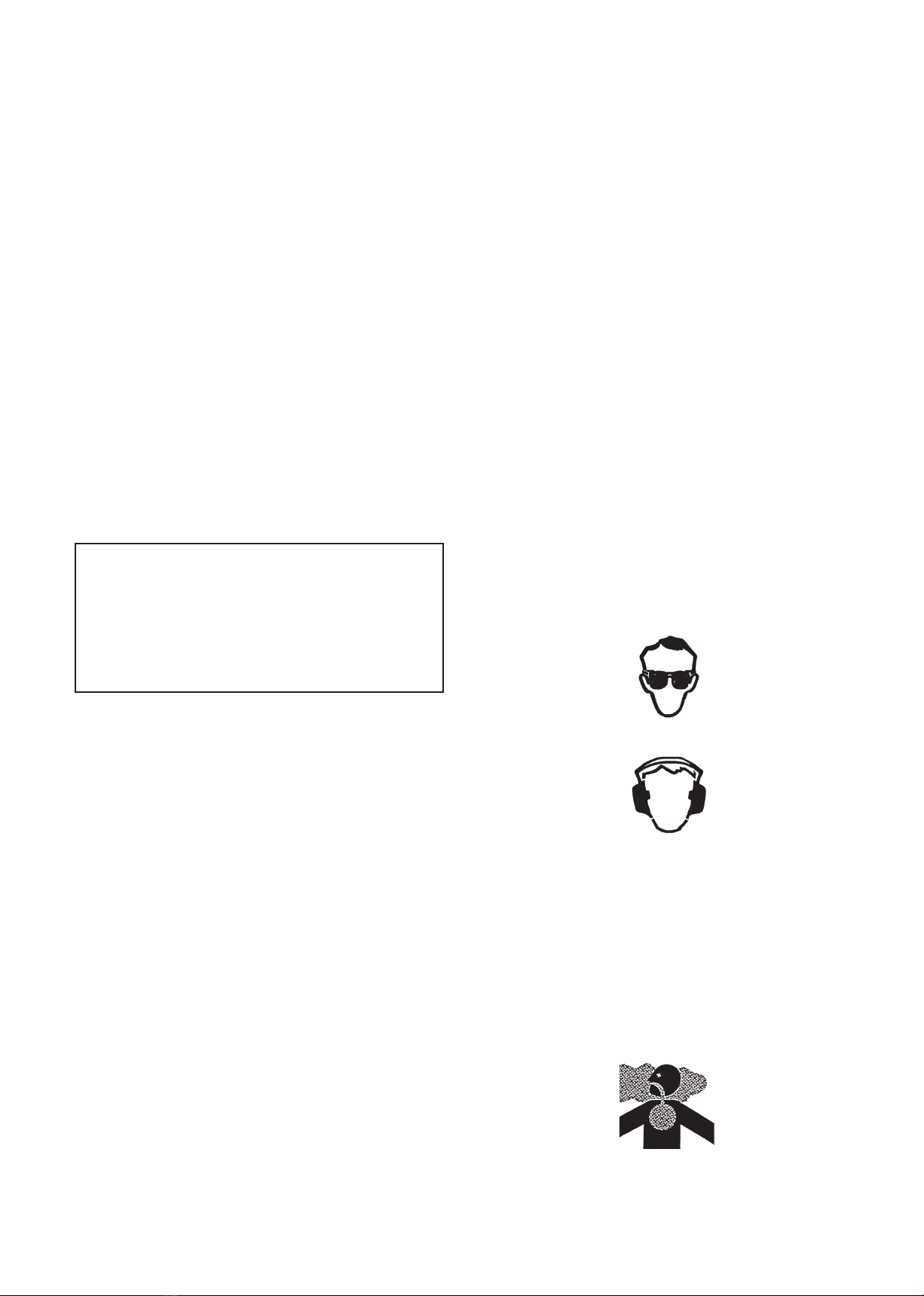
Always wear eye protection that complies with ANSI
(American National Standards Institute) Z87-1.
4. Always wear hearing protection.
5. Always wear heavy, long pants, a long sleeved
shirt, boots and gloves. Do not wear loose clothing,
jewelry, short pants, sandals, or go barefoot.
Secure hair so it is above shoulder length.
6.
Never operate this Multi-Cutter when you are tired, ill, or
under the influence of alcohol, drugs or medication.
7.
Never start or run the engine inside a closed room or
building. Breathing exhaust fumes can cause death.
8. Keep handles clean of oil, fuel and dirt.
Introduction
Model Name _______________
Serial No. ________________

— US-5 —
Multi-Cutter with Tool
Attachments Safety
1. Make sure the Unit is assembled correctly and that
the tool attachment is correctly installed and
securely fastened as instructed in the Assembly
section.
2. Inspect the Unit before each use. Replace
damaged parts. Check for fuel leaks. Make sure
all fasteners are in place and tightened securely.
Follow the maintenance inst-ructions beginning
on page US-13.
3. Make sure the tool attachment does not rotate at
engine idle speed. Refer to Idle Speed Adjustment,
page US-13.
4. Inspect the tool attachment head and replace any
parts that are cracked, chipped or damaged before
using the Multi-Cutter.
5. Install all required shields and guards prior to
operating the Multi-Cutter or its attachments.
Note: Remove blade cover from Hedgetrimmer
attach-ments prior to operation.
6. Never use a tool attachment head or replacement
parts that are not approved by MARUYAMA.
7. Maintain the Multi-Cutter power unit and tool
attach-ments according to the recommended
maintenance intervals and procedures in the
Maintenance section.
8. Shut off the engine and wait until the tool
attachment head has completely stopped moving
before checking, performing maintenance on or
working on the Multi-Cutter.
9. If running problems or excessive vibration occur,
stop immediately and inspect the unit for the
cause. If the cause cannot be determined or is
beyond your ability to correct, return the Multi-
Cutter with tool attachment to your servicing
dealer for repair.
Fuel Safety
1. Gasoline is highly flammable and must be handled
and stored carefully. Use a container approved for
fuel to store gasoline and/ or fuel/ oil mixture.
2. Mix and pour fuel outdoors, where there are no
sparks or flames.
3. Do not smoke near fuel or Multi-Cutter, or while
using the Multi-Cutter.
4. Do not overfill the fuel tank. Stop filling 1/4-1/2
in. (6 mm-13 mm) from the top of the tank.
5. Wipe up any spilled fuel before starting the
engine.
6.
Move the Multi-Cutter at least 10 ft. (3 m) away
from the fueling location before starting the engine.
7. Do not remove the fuel tank cap while the engine
is running, or right after stopping the engine.
8. Allow the engine to cool before refueling.
9. Drain the tank and run the engine dry before
storing the unit.
10. Store fuel and Multi-Cutter away from open
flame, sparks and excessive heat. Make sure fuel
vapors cannot reach sparks or open flames from
water heaters, furnaces, electric motors, etc.
10 ft. (3 m) minimum
— US-6 —
Pruner Operating Safety
1. THIS PRUNER CAN CAUSE SERIOUS INJU-
RIES. Read the instructions carefully. Be familiar
with all controls and the proper use of the Pruner.
2. The Pruner is designed to cut wood and can there-
fore be potentially dangerous. Careless or
improper use can cause serious or even fatal
injury.
3. This Pruner can conduct electricity. Do not use
where contact can be made with live electrical
circuits. Never use around electrical power
sources and lines. Failure to observe this warning
can result in serious injury or death.
4. Beware of where material will fall after being cut.
Do not stand underneath falling material.
5. Inspect your work area before you begin. Remove
objects such as broken glass, nails, wire and rocks
which can become dangerous projectiles if thrown
by the Pruner. Remove string, rope or similar
materials which can become entangled in the
Pruner head.
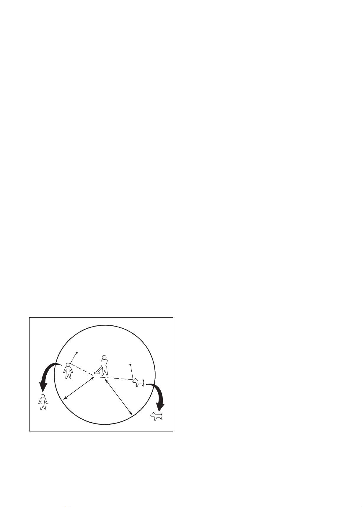
6. This Pruner will throw objects and cut. Keep
children, bystanders and animals outside a 50 ft.
(15m) radius from the operator and Trimmer.
Beyond the 50 ft. (15 m) there still may be a risk
of injury to bystanders from thrown objects. It is
recommended that bystanders wear eye protection.
A thrown object can ricochet.
7. If you are approached while operating the Pruner,
stop the engine and Pruner chain motion.
8.
Use the Pruner only in daylight or good artificial light.
9. Do not put hands or feet near or under any rotating
parts. Keep clear at all times. Keep all parts of
your body away from the Pruner chain and hot
surfaces such as the muffler.
10. Keep firm footing and balance. Do not overreach.
11. Watch for wires. Keep sufficient distance away
from electrical power lines.
12. Use the right tool for the job. Do not use the
Pruner for any job that is not recommended by
MARUYAMA.
50 ft. (15 m) minimum

— US-7 —
Product description
1. Chain and Guide Bar
2. Pruner Head
3. Shaft Assembly
4. Gearcase
1. Chain and Guide Bar
2. Pruner Head
3. Shaft Assembly
4. Gearcase
QC-PS
QC-PL
3
3
2
2
1
1
4
4

— US-8 —
Safety and Instruction Decals
Safety decals and instructions are easily visible to the operator and are located near any area of potential
danger. Replace any decal that is damaged or lost.
Symbol explanation
ON SHAFT
(Part No. 231896)
ON SHAFT
(Part No. 219937)
Read and understand this Owner’s/ Operator’s Manual.
•
Wear head protection, where there is a risk of falling objects.
•
Wear eye protection, while operating the Pruner.
•
Wear ear protection, while operating the Pruner.
Wear foot protection, while operating the Pruner.
Wear gloves, while operatingthe Pruner.
•
The distance between the machine and bystandards shall be at least 15m.
•
Watch for electrical shock. Keep sufficient distance away from electrical power line.
•
The distance between the machine and electrical power line shall be at least 10m (30ft.).

— US-9 —
Assembly
Guide bar and saw chain installation
1. Slot the saw chain in the groove of the guide bar,
ensuring that the cutter section of the saw chain is
facing the front.
2. Engage the saw chain into the sprocket.
3. Insert the groove of the guide bar into the pruner’s
main unit and adjust the regulating screw to ensure
that the adjuster is inserted in the circular hole of
the guide bar.
4. Put the chain cover on and temporarily screw it in
place using a nut, to the extent that the guide bar
can be moved.
5. Lift up the leading edge of the guide bar and using
a screw driver turn the regulating screw clockwise
to tighten the saw chain until the saw chain
slightly touches the lower side of the guide bar.
6. Securely tighten the nut on the chain cover, using
the box spanner, provided as an accessory with the
product.
7. Verify that the saw chain on the central section of
the guide bar can be lifted by the fingers 3 to 4
mm off the guide bar.
CAUTION
• In order to prevent cuts, be sure to
wear gloves when handling the guide
bar and saw chain.
• Maintain the tension of the saw chain
properly at all times.
• If not enough tension is applied to the
saw chain it can easily be dislodged
when the saw chain is in motion.
• If too much tension is applied to the
guide bar, saw chain and clutch may
wear prematurely as a result.
Cutter facing front
Saw chain
Guide bar
Circular hole on guide barGroove of guide bar
Sprocket
Adjuster
Chain cover
Nut
Regulating
screw
Nut
Lift up leading edge of guide bar
Regulating screw
Saw chain lightly touches the guide bar
Loosen Tighten
Cutter facing front
Saw chain
Guide bar
Circular hole on guide barGroove of guide bar
Sprocket
Adjuster
Chain cover
Nut
Regulating
screw
Nut
Lift up leading edge of guide bar
Regulating screw
Saw chain lightly touches the guide bar
Loosen Tighten
2
1
Locating Hole
4
3
1. Clamping Screw
2. Locating Screw
3. Gearcase
4. Shaft Assembly
Lifts up 3 to 4 mm when lifted lightly by fingers
Oil tankcap
Oil tank
Cutter facing front
Saw chain
Guide bar
Circular hole on guide barGroove of guide bar
Sprocket
Adjuster
Chain cover
Nut
Regulating
screw
Nut
Lift up leading edge of guide bar
Regulating screw
Saw chain lightly touches the guide bar
Loosen Tighten
Lift up leading edge of guide bar
Regulating screw
Saw chain lightly touches the guide bar
Loosen Tighten

— US-10 —
Installing Shaft and Gearcase
Attach the driveshaft tube assembly to the gearcase
assembly.
NOTE: Carefully inspect both side of the shaft
assembly. The arrow marking side of the
shaft assembly positions to the power unit.
The no marking side of the shaft assembly
connects to the gearcase assembly.
Insert the shaft assembly into the gearcase assembly
whilerotating the driveshaft to engage the splines.
Align the locating hole and install the locating screw
through the side of the gearcase. Then tighten the
clamping screw. If properly installed, rotating the
end of the driveshaft will cause the saw chain to
move.
Attaching and Detaching for the Power
Unit and the Shaft Assembly
Attaching
1 First, loosen the clamping knob before attaching
the shaft assembly to the shaft coupler.
Note : Do not over loosen the clamping knob or it
may fall out.
2 Insert the shaft assembly to the shaft coupler with
the positioning hole faced up as shown. Connect
the both drive shafts completely in the matching
position by moving the shaft assembly to forward
and backward and left turn and right turn. When
the shaft assembly is positioned correctly, spring
tensioned positioning lever will be returned to the
initial position.
3 Tighten the clamping knob firmly.
Detaching
1 First, loosen the clamping Knob before detaching
the shaft assembly to the shaft coupler.
2 Pull out the shaft assembly from the shaft coupler
with hold the positioning lever down.
3 Note : Do not over loosen the clamping knob or it
may fall out.
Clamping Knob
Shaft Coupler
Positioning Lever
Positioning Hole
Shaft Assembly
Insert
TightenLoosen
Positioning
Lever
Positioning lever is
lowered state
Positioning lever is
raised state
Incorrect Assembled
Correct Assembled
Clamping Knob
Shaft Assembly
Positioning Lever
Removal
Push down
Loosen
Locating Hole
Shaft Assembly
Driveshaft
Arrow Mark
Splined
Gearcase
Clamping Screw
Locating Screw

— US-11 —
Before operation
Chain oil
1) Adding oil
1. Remove the oil tank cap and pour the chain oil
(SAE #10W-30) into the oil tank.
2. Once the oil has been poured into the oil tank,
tighten the oil tank cap to securely close the tank.
The regulating screw has three positions, Minimum,
Intermediate and Maximum, only.
The regulating screw is set to Intermediate at the time
of shipping. It is recommended that the product be used
with this setting for ordinary use.
• Increase the discharging rate when cutting hard
branches or branches with a lot of resin (pitch),
or when the viscosity of the oil is high during
winter.
1. Insert a minus screw driver into the regulating
screw at the bottom of the main unit.
2. When applying pressure with the minus screw
driver, turn the screw to the right (clockwise) to
reduce the discharging rate and to the left
(counterclockwise) to increase the discharging
rate.
3. Turn the engine on and turn the saw chain, with the
guide bar facing the ground or tree. Oil will attach
to the ground or tree, if the oil is discharging.
2
1
Locating Hole
4
3
1. Clamping Screw
2. Locating Screw
3. Gearcase
4. Shaft Assembly
Lifts up 3 to 4 mm when lifted lightly by fingers
Oil tankcap
Oil tank
• Ensure that the guide bar and saw
chain are installed on the pruner before
verifying the discharging rate of the
chain oil. The rotator will be exposed
and therefore dangerous if the guide
bar and the saw chain are not installed
on the pruner.
DANGER
CAUTION
• Using the pruner with a saw chain too
loose may result in the saw chain
becoming dislodged and could cause an
accident. Please be sure to check the
tension of the saw chain before starting
any work.
Minimum
Maximum
Intermediate
Regulating screw
Be sure to turn the screw while applying
pressure to it with the screwdriver.
CAUTION
•
It may take some time before the oil
begins to discharge once the oil has
been added to a new product or when
oil has been added to an empty tank. Do
not turn the pruner on at a high speed
in such circumstances.
• When a new chain is to be used, immerse
the chain in chain oil for some time
prior to installing it on the pruner, or
pour the oil directly on to the chain and
the guide bar, after installing it on the
pruner. If they are not properly lubri-
cated with oil the pruner may seize.

— US-12 —
Operation
Working position
1. Choose a working position where the inclination
of the pole remains at 60 degrees or less.
2. Start cutting from the lower branches first so that
the branches will fall off easily when cut.
3.
The cut branches may fall towards the worker, so be sure
to select a location that enables a stable footing and
provides an easy escape in the case of an emergency.
Cutting wood
1. Turn the pruner on full throttle and press the saw
chain lightly against the wood to cut.
2. The cutting capacity is reduced when the engine
revolution is slowed down and the saw chain is
pressed hard against the wood.
IMPORTANT:
•
Pressing the saw chain hard against the wood not
only tires the operator quicker but also quickens
the wear of the saw chain and guide bar.
• If wood cannot be cut without pressing the
saw chain hard against it, this indicates that
the saw chain is becoming dull. In such cases,
either sharpen the saw chain or replace it
with a new chain.
Pruning thick branches
Attempting to cut a thick branch in one go often results
in the guide bar jamming in the branch or otherwise
encountering difficulties in cutting. The method
described below makes cutting thick branches easier:
1. First of all, cut a section slightly away and on the
lower side of the desired area of the branch to be
cut.
2. Then, start cutting from the upper side of the
branch.
3. hereafter, cut into the
lower side where the
desired area of branch
is to be cut.
4. Finally, cut through
from the upper side
where the branch is to
be cut, cutting the
branch off.
IMPORTANT: If the guide bar or saw
chain jams into the branch, do not
force it. Widen the cut using a wedge to
remove the pruner and try cutting it
again. Forcing the pruner may damage
the main unit of the pruner and cause
a malfunction of the pruner.
• Do not stand immediately below the
branch that is to be cut. The branch
may fall directly below and the branch
may also bounce off other branches or
the ground in an unexpected direction
and cause injury to the worker.
• Do not allow anyone to enter within a
15 meter radius.
• The Pruner is not insulated to prevent
electric shock. Keep it away from any
power lines with at least 15 meters
when working, as there is threat of
electrocution.
DANGER
WARNING
•
Wear a hat or helmet, protective glasses,
gloves and ear plugs while working.
Furthermore, wear a dust mask
whenever a lot of pollen or chipping
powder is expected, which may be
harmful for the health.
①
②
③
④
60°
①
②
③
④
60°
— US-13 —
Saw chain tension adjustments
1. Turn the nut on the chain cover once to loosen it.
2. Lift up the leading edge of the guide bar and turn
the regulating screw to tighten the saw chain.
Turning the screw clockwise tightens the saw
chain, whereas turning it counterclockwise looses
the saw chain.
3. Securely tighten the nut on the chain cover.
4. Verify that the saw chain on the central section of
the guide bar can be lifted with fingers 3 to 4 mm
off the guide bar.
Maintenance
Maintenance, replacement or repair of emission control
devices and systems may be performed by any repair
establishment or individual; however, warranty repairs
must be performed by a dealer or service center autho-
rized by MARUYAMA Manufacturing Company, Inc.
The use of parts that are not equivalent in performance
and durability to authorized parts may impair the effec-
tiveness of the emission control system and may have a
bearing on the outcome of a warranty claim.
Maintenance on today’s low-emission engines is
even more critical for longest life and best perfor-
mance. particularly critical are air and fuel filters,
spark plug heat range, cooling air intake area and
proper gaps of coil and plug.
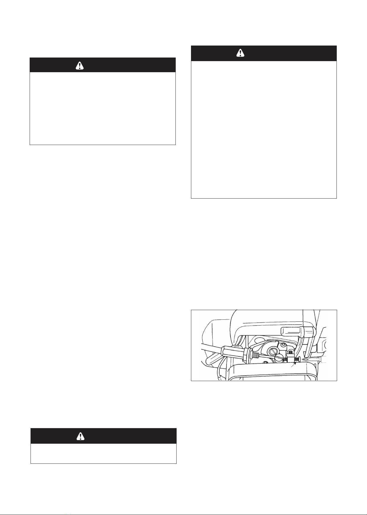
Idle Speed Adjustment
This Multi-Cutter is equipped with non-adjustable fuel
mixture carburetor. The engine idle speed is the only
adjustment for the operator.
The Attached Tool may be rotating/ moving during idle
speed adjustment. Wear the recommended personal pro-
tective equipment and observe all safety instructions.
Keep hands and body away from the Attached Tool.
When the throttle trigger is released, the engine should return
to an idle speed. The correct speed for models M27QC,
M30QC are 2700 - 3300 RPM, and for M42BK-QC is 2400 -
2800 RPM, or just below the clutch engagement speed. The
Attached Tool must not rotate/move and the engine should
not stall (stop running) at engine idle speed.
To adjust the engine idle speed, rotate the idle speed
adjustment screw on the carburetor.
● Turn the idle speed screw in (clockwise) to increase
the engine idle speed.
● Turn the screw out (counterclockwise) to decrease
the engine idle speed.
If idle speed adjustment is necessary, and after adjust-
ment the Attached Tool rotates/moves or the engine
stalls, stop using the Multi-Cutter immediately!
Contact your local authorized MARUYAMA Dealer for
assistance and servicing.
WARNING
• Idle speed adjustment should be
checked each time the unit is operated.
POTENTIAL HAZARD
•
Engine must be running to make car-
buretor adjustments.
•
When engine is running, attached tool
and other parts is rotating / moving
and other parts are moving.
WHAT CAN HAPPEN
•
Contact with rotating / moving tool or
other moving parts could cause seri-
ous personal injury or death.
HOW TO AVOID THE HAZARD
•
Keep hands, feet and clothing away from
attached tool and other moving parts.
•
Keep all bystanders and pets away from unit
while making carburetor adjustments.
WARNING
Idle Speed Adjustment Screw
WARNING
• When using the pruner be sure to turn
the engine off before making any
inspections or any adjustments.
• Do not make any adjustments when the
guide bar or saw chain is still hot
immediately after using the pruner.
Wait until it has cooled before making
any adjustments.

— US-14 —
Sharpening saw chain
Whenever wood chips become small and fine or the
wood cannot be cut without pressing the pruner hard
against it, then it may be necessary to sharpen the saw
chain.
1. Tighten the saw chain slightly firmer than usual
then secure the pruner’s main unit.
2. Place a file with a 4.0 mm (5/32 in.) diameter
against the cutter and extend 1/5 of it beyond the
cutter.
3. Press the file against the cutter at its base in a
30-degree angle from the vertical line and move
the file straight ahead from the inner side to the
outer side of the cutter.
4. Shift the file so that it remains in a 90-degree
angle against the guide bar.
5. Once one side of the cutter is sharpened, sharpen
the other side of the cutter. Be sure to keep the
length and angle uniform throughout.
IMPORTANT:
• The spark arrester should be
inspected and cleaned after every 25
hours of use.
•
Replace the screen if it cannot be
thoroughly cleaned, or if it is damaged.
Adjusting depth gauge
The depth gauge determines how deep the cutter cuts
into the wood.
1. When the cutter lengths become shorter due to
sharpening, the depth gauge must also be cut
back.
2. Cut down the depth gauge using a flat file in a
way that the depth gauge is positioned 0.64 mm
(0.025 in.) lower than the leading edge of the
cutter.
3. Once cut back, grind the tip of the depth gauge
round.
Sharpen shaded area
Maintain uniform lengths of cutters
30°
90° File
Guide bar
30°
0.64mm
Depth gauge
55°
80° 30°
Depth gauge setting Top plate
cutting angle
Side plate filing angle Top plate filing angle
Oil discharge holes
(also on the reverse side)
0,3 mm or more
Sprocket Worn condition
Grease plug
Gear case
Cutter Maintenance Specifications
— US-15 —
IMPORTANT:
Be sure that the depth gauge is not cut
back too far, as doing so will result in
a faster deterioration of the cutter.
Guide bar care
1. When work using the pruner is finished for the
day, remove the guide bar and saw chain from the
pruner.
2. Remove any wood chips or other particles
attached to the groove of the guide bar or in the oil
hole. Be particularly certain that no particles are
clogging the oil hole.
3. Remove wood chips and other particles around the
oil discharge hole and around the sprocket on the
main unit of the pruner.
IMPORTANT:
• When installing the guide bar,
occasionally switch it to the top and
bottom to prevent uneven wear and to
extend the life of the guide bar.
• If the oil discharge hole becomes
clogged by wood chips or other particles
the pruner could seize up.
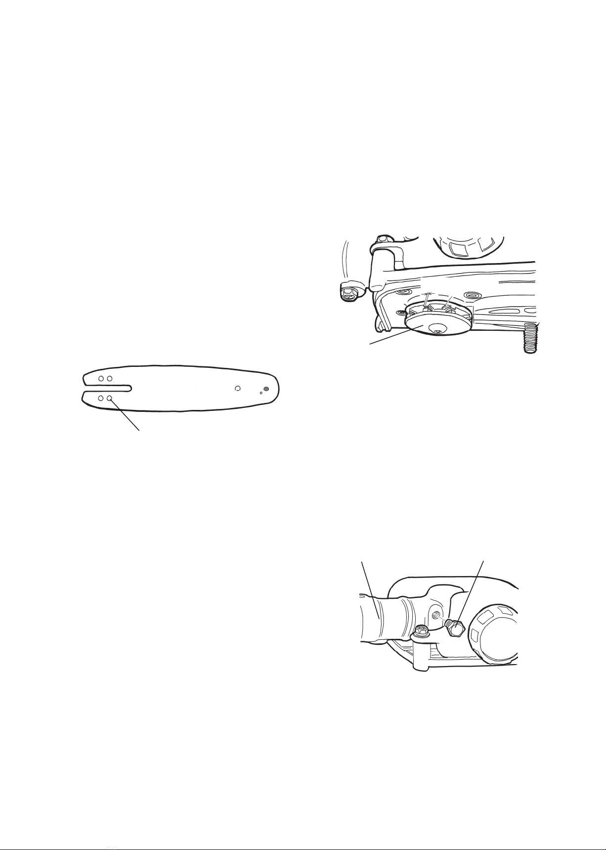
Inspection of sprocket
1. Inspect the sprocket to ensure that the screw is not
loose or that it is not worn out.
2. If the sprocket is worn by 0.3 mm or more, as
shown in the diagram below, replace the sprocket.
Continuing to use the pruner with the sprocket in
such a condition will shorten the life of the saw
chain.
Gear case
1. Remove the gear case from the shaft assembly.
2. Remove the grease plug and prepare some
lithiumtype grease.
3. Inject enough grease (about 10g) so that some of it
spills out through the spline hole, to which the
drive shaft is inserted.
0.64mm
Depth gauge
55°
80° 30°
Depth gauge setting Top plate
cutting angle
Side plate filing angle Top plate filing angle
Oil discharge holes
(also on the reverse side)
0,3 mm or more
Sprocket Worn condition
Grease plug
Gear case
0.64mm
Depth gauge
55°
80° 30°
Depth gauge setting Top plate
cutting angle
Side plate filing angle Top plate filing angle
Oil discharge holes
(also on the reverse side)
0,3 mm or more
Sprocket Worn condition
Grease plug
Gear case
0.64mm
Depth gauge
55°
80° 30°
Depth gauge setting Top plate
cutting angle
Side plate filing angle Top plate filing angle
Oil discharge holes
(also on the reverse side)
0,3 mm or more
Sprocket Worn condition
Grease plug
Gear case

— US-16 —
Troubleshooting
If further assistance is required, contact your local authorized MARUYAMA service dealer.
Maintenance Period
●: Service to be performed by an authorized MARUYAMA engine dealer.
■: Service more frequently under dusty conditions.
NOTE:
The service intervals indicated are to be used as a guide.
Service to be performed more frequently as necessary depending on operating condition.
Use MARUYAMA standard 50:1 two-stroke engine oil.
Maintenance Daily Every
25 hours
Every
50 hours
Every
100 hours
Check and replenish fuel ●
Check for fuel leakage ●
Check bolts, nuts and screws for tightness or missing ●
Check engine idle speed adjustment ●
■Clean air lter element ●
Clean spark plug and adjust eleatrode gap ●
■Remove dust and dirt from cylinder ns ●
●Clean spark arrester ●
Tighten bolts and nuts ●
●Remove carbon deposits in exhaust port ●
Replace fuel lter ●
●
Remove carbon deposits on piston head and combustion chamber
●
●Remove carbon deposits in transfer port ●
Replece fuel tube, fuel tank cap gasket It is recommended to replace every 3 years
Problem Cause Action
Engine Will Not Start • STOP switch set to off position
• Empty fuel tank
• Primer bulb wasn’t pushed enough
• Engine ooded
• Move switch to on position
• Fill fuel tank
• Press primer bulb until fuel flows
through fuel return line
•
Use warm engine starting procedure
Engine Will Not Idle Idle speed set incorrectly Set idle speed
Engine Lacks Power or Stall When
Cutting
Throttle wire has come loose
Dirty air lter
Clogged spark arrester or exhaust port.
Tighten throttle wire
Clean or replace air filter
Clean spark arrester or exhaust port.

— US-17 —
Specifications
Emission durability of 300 hours.
※1
. Dry weight without fuel, Chain Bar and Strap .
M27QC with
QC-PS QC-PL
Weight ※1(lbs.) 12.0 (5.5kg) 13.3 (6.0kg)
Engine Displacement (cm3)
25.4
Anti Vibration Dual Isolatin-grip and engine mount
Carburetor Walbro Diaphragm Type
Ignition Syatem Solid State
Fuel Tank Capacity (qts.) 0.63 (0.6L)
Gas to Oil Ratio 50:1
Spark Plug NGK BPM8Y
Spark plug Gap (in.) .024-.028 (0.6-0.7mm)
EPA and CARB Approved
Phase 3, Tier 3
M30QC with
QC-PS QC-PL
Weight ※1(lbs.) 11.8 (5.4kg) 13.1 (5.9kg)
Engine Displacement (cm3)
30.1
Anti Vibration Dual Isolatin-grip and engine mount
Carburetor Walbro Diaphragm Type
Ignition Syatem Solid State
Fuel Tank Capacity (qts.) 0.63 (0.6L)
Gas to Oil Ratio 50:1
Spark Plug NGK BPM8Y
Spark plug Gap (in.) .024-.028 (0.6-0.7mm)
EPA and CARB Approved
Phase 3, Tier 3
M42BK-QC with
QC-PS QC-PL
Weight ※1(lbs.) 25.8 (11.7kg) 27.0 (12.3kg)
Engine Displacement (cm3)
41.5
Anti Vibration Dual Isolatin-grip and engine mount
Carburetor Walbro Diaphragm Type
Ignition Syatem Solid State
Fuel Tank Capacity (qts.) 1.06 (1.0L)
Gas to Oil Ratio 50:1
Spark Plug NGK BPM8Y
Spark plug Gap (in.) .024-.028 (0.6-0.7mm)
EPA and CARB Approved
Phase 3, Tier 3

— ES-1 —
Declaración de garantía limitada
Todos los productos Maruayama están garantizados al comprador original de estar libres de defectos en
materiales o fabricación desde la fecha de compra durante los siguientes periodos:
Para la vida de uso de ejes de acero sólido y las bobinas de arranque.
Garantía comercial Iron 5™ de 5 años de uso.
1 año para uso residencial o 2 años para uso comercial con aceite de otra marca.
90 días para uso de alquiler.
Motor – referirse al texto de garantía del fabricante del motor. Fabricado por Maruyama Los
motores Maruyama están cubiertos por esta garantía limitada.
Cualquier parte del producto Maruyama que se determine defectuoso durante el periodo aplicable de garan-
tía será, a discreción de Maruyama, reparada o reemplazada, sin costo. Durante el proceso de garantía se
tomará en consideración el producto de Maruyama que se considere defectuoso y que sea entregado a un
servicio autorizado de Maruyama durante el periodo aplicable de la garantía.
No se cobrará al comprador por la tarea de diagnóstico que determine que una pieza en garantía es defec-
tuosa, si se realiza en un centro de distribución de Maruyama. Cualquier pieza en garantía cuyo cambio no
esté programado como mantenimiento necesario, o que esté programada sólo para revisión ordinaria con
vistas a su “reparación o cambio según sea necesario” estará cubierta durante el período de garantía.
Cualquier pieza en garantía, cuyo cambio esté programado dentro del mantenimiento necesario, estará
cubierta hasta el primer cambio programado que le corresponda. Maruyama Mfg Co., Inc. es responsable de
los daños ocasionados a otros componentes del motor por el fallo de una pieza que aún esté en garantía. El
comprador es responsable de realizar las tareas de mantenimiento necesarias tal y cómo se definen en el
MANUAL DEL PROPIETARIO U OPERADOR de Maruyama Mfg Co., Inc.
GARANTÍAS DE PARTES RELACIONADAS A EMISIONES: Además de dicha cobertura, Maruyama MFG.
Co., Inc., reparará o reemplazará, sin costo, al comprador original, y cada comprador subsiguiente, cualquier
parte(s) relacionada(s) a emisiones determinadas de ser defectuosas en materiales o fabricación durante
dos (2) años a partir de la fecha de entrega. Partes relacionadas a emisiones incluyen la bobina com-
pleta de arranque, el rotor de arranque, la bujía, el convertidor catalítico en el depósito de combusti-
ble. Cualquier parte de reemplazo de comparable desempeño y durabilidad se pueden utilizar en
manutención y reparación y esto no disminuirá la obligación de garantía de Maruyama MFG. Co., Inc.
®

— ES-2 —
ESTA GARANTÍA NO CUBRE:
1. Partes de manutención (incluso defectos en materiales y fabricación), incluso mangueras, bujías, cuerdas
de arranque, filtros de aire y combustible, zapatos de embrague, amortiguadores de vibración, cables de
acelerador, y todos los accesorios de corte.
2. Gastos suplementarios, incluso envío y manejo, viaje, pago de pérdida de tiempo, o pago por inconvenien-
cia y almacenamiento.
3. Alteraciones o modificaciones incluso respuestos genéricos no autorizados por Maruyama.
4. Desgaste, accidentes, abuso, uso incorrecto, negligencia, combustibles, lubricantes, mezclas de combusti-
ble inadequadas (cuando sea aplicable), o no realizar manutención u operación del producto de acuerdo a
las instucciones aprobadas por Maruyama.
La reparación o cambio según lo estipulado en la presente garantía es la única solución del usuario.
Maruyama no se hará responsable de ningún daño fortuito o consecuencial del incumplimiento de cualquier
garantía expresa o implícita de estos productos salvo hasta el límite estipulado por la legislación aplicable.
Cualquier garantía implícita de comerciabilidad o idoneidad para un fin particular de estos productos se
restringe al período de garantía tal y cómo se define en la declaración de garantía limitada. Maruyama se
reserva el derecho a modificar o mejorar el diseño del producto sin previo aviso y no asume ninguna
obligación de actualizar los productos previamente fabricados.
Esta garantía le ofrece derechos legales específicos, que pueden variar de un Estado a otro.
El propietario y el distribuidor se responsabilizarán de que la Tarjeta de registro de garantía sea correcta-
mente cumplimentada y enviada a Maruyama U.S., Inc. Para obtener el servicio de garantía se solicitará una
prueba de compra o registro.
Para encontrar al distribuidor autorizado de Maruyama más cercano, contacte con:
Maruyama U.S., Inc.
4770 Mercantile Drive, suite100,
Fort Worth, TX
76137
U.S.A.
(940)383-7400
www.maruyama-us.com
This manual suits for next models
9
Table of contents
Languages:
Other Maruyama Cutter manuals

Maruyama
Maruyama QC-HT User manual

Maruyama
Maruyama M42BK-QC Owner's manual

Maruyama
Maruyama M30BK-S User manual

Maruyama
Maruyama M27QC Owner's manual

Maruyama
Maruyama QC-S User manual

Maruyama
Maruyama QC-E User manual

Maruyama
Maruyama MC2600RS Owner's manual

Maruyama
Maruyama BM240 Owner's manual

Maruyama
Maruyama M270QC Owner's manual


