Marway Optima 833 Series User manual

Optima™833 Series
Power Distribution Units
Operating Guide and Reference
Sep 2021 : P/N 501055-000 Rev B

Page 2
Optima 820 Series
1General 3
1.1 Documentation Symbols (EN) ............................................... 3
1.2 Safety Notices (EN) ................................................................ 3
1.3 Symboles de Documentation (FR) ........................................ 4
1.4 Avis de sécurité (FR) .............................................................. 4
1.5 General Description ............................................................... 5
1.6 Product Models ...................................................................... 5
1.7 Product Ratings...................................................................... 6
2Installation 7
2.1 Installation Notes ................................................................... 7
3Operation 8
3.1 Startup.................................................................................... 8
3.1.1 Startup Without Conguring the Software..................... 8
3.1.2 Startup to Congure the Software ................................. 9
3.2 Ethernet and Serial Control................................................... 9
3.3 Breaker Controls .................................................................... 9
3.3.1 Main Breaker................................................................... 9
3.3.2 Branches........................................................................10
3.3.3 Controls Breaker ...........................................................10
3.4 Remote Switching / EPO Option..........................................11
3.4.1 Remote Override Switch ...............................................11
3.4.2 Remote Bus Connector.................................................12
3.5 Digital Power Meter..............................................................13
3.6 EMI Filter...............................................................................13
4Reference 14
5 Specications 15

Page 3
Optima 820 Series
1 General
1.1 Documentation Symbols (EN)
Safety and warning notices as well as general notices in this document are shown in a box with a symbol as follows:
Symbol for a life threatening danger.
Symbol for general safety notices (instructions and damage protection bans) or important
information for operation.
Symbol for general notices.
1.2 Safety Notices (EN)
Mortal danger - Hazardous voltage
• This product is classied as pluggable equipment. The mains inlet plug serves as the disconnect
device. The mains inlet plug shall be installed so that it is easily accessible.
• This product is equipped with a safety ground connection through the mains inlet plug, as well as
a redundant chassis ground screw on the rear panel. Ensure that the product is properly grounded
before applying power.
• Disconnect all power to the product prior to servicing control signal cabling.
• Do not open this product as it contains no user serviceable parts inside. All service concerns
should be directed to Marway Power Solutions.
• If this product is used in a manner which does not comply with this instruction manual, the
protection provided by the equipment may be impaired.
• All work on connections must be carried out under zero voltage (output disconnect), and may only
be performed by qualied and informed persons. Improper actions can cause fatal injury as well as
serious material damage.
• This product is intended for indoor use only and should not be exposed to excess moisture. Avoid
any use of liquids near the equipment, and condition which cause condensation.
• This product is intended for installation in a restricted access location by a skilled person.
• This product is intended for use by an instructed person.
• The equipment is only approved for use within the connection limits stated on the product label.
• The ratings for all output receptacles are marked on the chassis. Be sure to observe the ratings for
all connected load equipment.

Page 4
Optima 820 Series
1.3 Symboles de Documentation (FR)
Les consignes de sécurité et avertissements, ainsi que les avis généraux gurant dans ce document sont présentés dans
un encadré avec un symbole, comme illustré ci-dessous.
Symbole pour les avis de danger potentiellement mortel.
Symbole pour les avis de mise en garde pour la sécurité personnelle ou pour la protection de
l’équipement.
Symbole pour les avis importants concernant le fonctionnement.
1.4 Avis de sécurité (FR)
Danger de mort – Tension dangereuse
• Ce produit est classé comme un équipement enchable. La prise d’alimentation secteur sert de
dispositif de déconnexion. La prise d’alimentation secteur doit être installée de manière à être
facilement accessible.
• Ce produit est équipé d’une mise à la terre de sécurité via la prise d’alimentation secteur,
ainsi que d’une vis redondante de mise à la terre du châssis. Assurez-vous que le produit est
correctement mis à la terre avant de le mettre sous tension.
• Débranchez toute alimentation électrique du produit avant d’effectuer l’entretien du câblage des
signaux de commande.
• N’ouvrez pas ce produit, car il ne contient aucune pièce réparable par l’utilisateur. Tous les
problèmes de service doivent être adressés à Marway Power Solutions.
• Si ce produit est utilisé d’une manière non conforme au présent manuel d’instructions, la
protection fournie par l’équipement peut être compromise.
• Tous les travaux sur les connexions doivent être effectués sous une tension nulle et ne doivent
être effectués que par des techniciens qualiés et compétents. Des actions inappropriées peuvent
entraîner des blessures mortelles et des dommages matériels graves.
• Ce produit est conçu pour une utilisation à l’intérieur uniquement et ne doit pas être exposé à
une humidité excessive. Évitez toute utilisation de liquides à proximité de l’équipement et les
conditions susceptibles de provoquer de la condensation.
• Ce produit est destiné à être installé par une personne qualiée dans un endroit à accès restreint.
• Ce produit est destiné à être utilisé par une personne qui a reçu des instructions appropriées.
• L’utilisation de l’équipement est approuvée uniquement dans les limites de connexion indiquées
sur l’étiquette du produit.
• Les valeurs nominales de toutes les prises de sortie sont indiquées sur leur boîtier. Assurez-vous
de respecter les valeurs nominales de tous les équipements de charge raccordés.

Page 5
Optima 820 Series
1.5 General Description
The Optima 833 Series (model numbers MPD 833XXX) is a family of fteen power distribution units (PDUs) designed for
use with 120/208 Vac 3-phase supply power.
Each PDU receives mains power through a NEMA L21-30P inlet located on either the front or rear panel depending on the
model. Power is distributed as 120 and/or 208 Vac through eight branch circuits, each outtted with a variety of optional
outlets.
All models include an EMI lter, surge suppression, and remote-EPO feature. All models includes one unswitched NEMA
5-20R duplex receptacle which is not controlled by the remote-EPO feature. There are two styles of outlet congurations.
The rst is where all outlets are 5-20R. These are separated into four circuits of four outlets. The second style includes
three circuits of four 5-20R outlets, two circuits each with one L5 or L6 twist lock outlet, and one L21-20R outlet which is
fed directly from the main breaker (there is no branch breaker).
All models are constructed of a steel chassis, and designed for xed mounting within a 3U rack space in an EIA-310
compliant rack enclosure.
This documentation is about the hardware elements of the Optima 833 Series of PDUs. For detailed
information about the software, you’ll need the Optima RCM User Guide : Software and Basic
Controls Reference located on our website at http://www.marway.com/docs.
1.6 Product Models
Models are primarily organized by what type of power inlet they have. Then by the outlet congurations. All models have
a continuous duty rating of 24 A per phase at the inlet (30 A maximum). All models have two unswitched 5-20R outlets in
addition to the switched outlets noted in the table below.
Inlet Configurations Switched Outlet Configurations
Front
Panel
Straight*
Front
Panel
Flanged*
Rear
Panel
Straight*
Straight
Blade
Outlets
Twist Lock
5-20R L5-20 L5-30 L6-20 L6-30 L21-30
833000 833005 833010 16
833001 833006 833011 12 2 1
833002 833007 833012 12 2 1
833003 833008 833013 12 2 1
833004 833009 833014 12 2 1
* A complete part number follows the format of 833NNN-RRR-DDD where:
• NNN is part of the base part number from the list of models.
• RRR denes the RCM capabilities where:
• –PSW = inlet power is monitored, outlets are switched
• DDD is a dash number where:
• –000 = the remote EPO, if present, is a Normally Open (N.O.) type
• –001 = the remote EPO, if present, is a Normally Closed (N.C.) type

Page 6
Optima 820 Series
1.7 Product Ratings
All models of the 833 Series have the same input rating. Outlet ratings vary depending on the outlet type.
Inlet Rating Outlet Ratings
NEMA L21-30P
120/208VAC
3ɸ4P5W
50/60Hz
24 A continuous
30 A maximum
120 Vac, 1ɸ, 16 A continuous (20 A max.) per NEMA 5-20R duplex receptacle
120 Vac, 1ɸ, 16 A continuous (20 A max.) per NEMA L5-20R receptacle
120 Vac, 1ɸ, 24 A continuous (30 A max.) per NEMA L5-30R receptacle
208 Vac, 1ɸ, 16 A continuous (20 A max.) per NEMA L6-20R receptacle
208 Vac, 1ɸ, 24 A continuous (30 A max.) per NEMA L6-30R receptacle
120/208 Vac, 3ɸ, 24 A continuous (30 A max.) per NEMA L21-30R receptacle
24 A continuous (30 A max.) total per phase regardless of receptacle combination
(Outlet combinations are for connection exibility, not for increased current capacity.)

Page 7
Optima 820 Series
2 Installation
2.1 Installation Notes
The following guidance must be followed for proper installation of the product.
1. Mounting: This product is designed for mounting in an EIA-310 compliant 19” rack. The user is responsible for
ensuring the mounting method provides adequate structural support for the product, and any attached cables. The
user is also responsible for ensuring the mounting location provides adequate ventilation to dissipate heat generated
during operation of the product. Ensure the product is securely mounted before applying power.
2. Chassis ground: The rear of the chassis includes a redundant chassis ground screw and ground wire. If desired for your
installation location, connect the chassis ground wire to the rack cabinet using an appropriate fastener.
3. Optionally, connect the appropriate cables between the PDU outlets and the equipment being powered by the PDU.
This may be done later according to the startup procedures suitable to the end-user’s equipment and application.
4. If applicable, connect the cabling between the PDU and remote EPO control panel.
5. PDU Main Breaker: Ensure the Main Breaker on the front of the PDU is in the off position before connecting the PDU’s
inlet cable to the facility power source. (It is best to switch all breakers to the off position.)
6. Facility Power Source: The single-phase facility power source for this product must include an overcurrent protective
device capacity as dened in the table below:
Main Inlet Continuous Current
Rating
Mains Protection
Required
NEMA 5-15P 12 A 15 A
NEMA 5-20P 16 A 20 A
NEMA L5-20P 16 A 20 A
NEMA L6-20P 16 A 20 A
IEC C20 16 A 20 A
NEMA L5-30P 24 A 30 A
NEMA L6-30P 24 A 30 A
EN — These products are heavy. The ange mounting ears are designed to hold the PDU securely
against the rack mounting rails, but are NOT designed to support the weight of the product
vertically. The end user is responsible for ensuring the product’s weight is properly supported by the
rack’s infrastructure (which may require adding support rails).
FR — Ces produits sont lourds. Les oreilles de montage à bride sont conçues pour maintenir
solidement l’unité de distribution de l’alimentation contre les rails de montage, mais NE sont
pas conçues pour soutenir le poids du produit verticalement. Il incombe à l’utilisateur nal de
s’assurer que le poids du produit est correctement supporté par l’infrastructure du bâti (ce qui peut
nécessiter l’ajout de rails de support).

Page 8
Optima 820 Series
3 Operation
A B C
Ethernet Serial Aux 1Aux 2
Values
Devices
Menu
Optima RCM
CB 5
OFFON
Main Breaker CB 1
OFFON
CB 2
OFFON
CB 3
OFFON
CB 4
OFFON
OFFON
OFFON
EPO Only
Off
Remote
Remote OverrideControls
Breaker
PRESS
RESET
Enable
Disable
Return
J 20 J 21
J 22
J 23
Enable
Disable
Return
Delay
Disable
Return
Rear Panel
Left Side
3.1 Startup
In order to monitor or control the system over Ethernet, it will need to be congured to run on your specic network.
However, to perform an electrical or installation validation test, or even to run the system indenitely without the use of
the network, the unit can be run without rst conguring the software.
By default, the system will enable all outlets, though it may take a minute or so before outlets are switched on after
power is applied. This delay is caused by the software system starting up, and eventually setting the state of each relay
according to congurable settings.
In the sections below, a startup process is described suitable for rst-time network setup, or running without the software.
The Main Breaker can be used to manually cut power from all outlets. However, even with the main
circuit breaker Off, as soon as the inlet of the PDU is plugged into a live facility outlet, the control
system of the PDU is powered, and the software will start running.
3.1.1 Startup Without Conguring the Software
It is assumed the PDU is not plugged into the facility power source.
1. Switch all breakers on the PDU control panel to the Off position.
2. Whether there is a remote EPO panel connected to the unit or not, toggle the Remote Override switch to the up
position EPO Only. (The label has changed over the years, but the up position always functions the same way.)
2.1 This switch position is required if there is no EPO panel.
2.2 If there is a remote panel, this puts the PDU into a local control mode, ignoring the remote On/Off controls, but
allowing the EPO signal.)
3. If there is a facility disconnect switch for the PDU inlet, switch that off.
4. Insert the PDU’s inlet connector into the facility mains power source. If there is a facility power disconnect, switch that
to the On position.
4.1 At this point, the PDU control system is energized. Outlets will not have power, because the PDU’s breakers are
off, but the software will begin its startup process. The default factory setting congures the software to switch
the outlet relays on, however, while the breakers are off, power is not actually delivered to the outlets. Allow about
a minute for the software to switch on the relays.

Page 9
Optima 820 Series
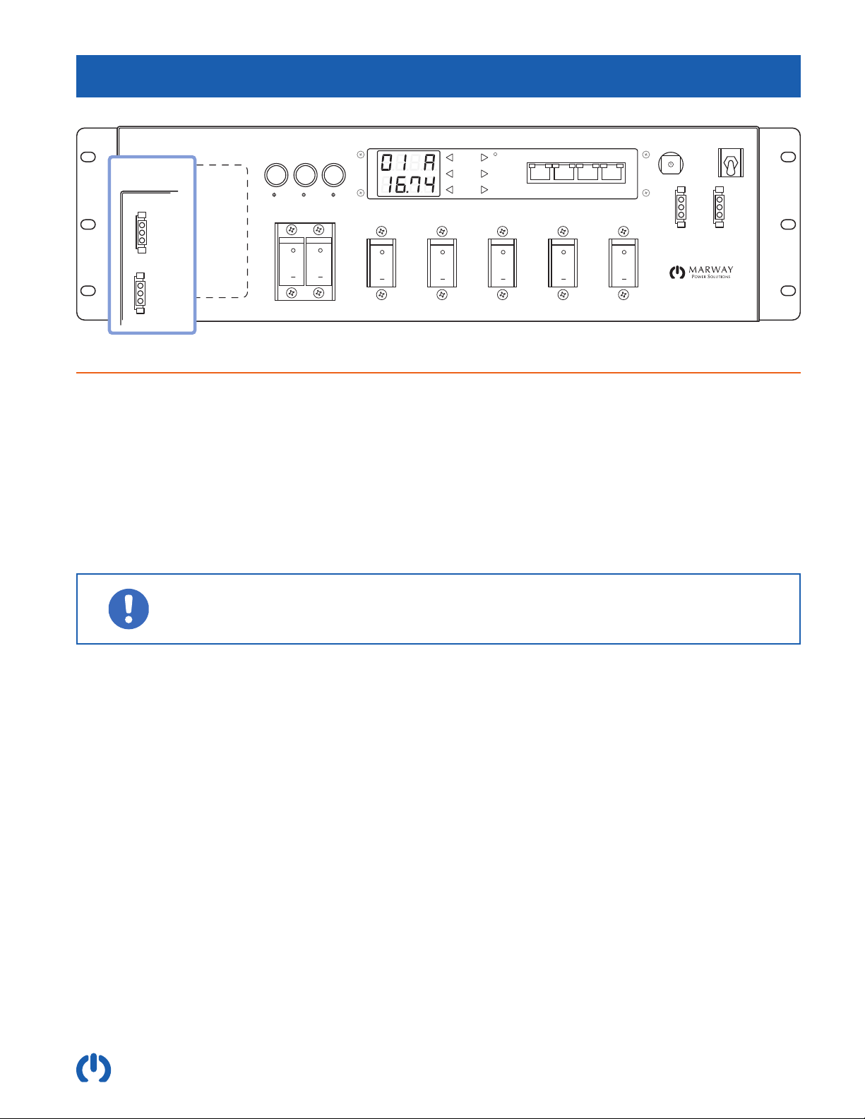
5. Switch the PDU’s Main Breaker to the On position, and the ΦA, ΦB, ΦC indicators will be lit. These indicators do not
necessarily mean power is applied to the outlets. They simply means the main breaker is on and power is available to
all the branch breakers. The internal outlet control relays, branch breakers, and remote switching/EPO system are able
to prevent power from reaching the outlets.
6. Switch each branch breaker to the On position. The internal outlet control relays, and remote switching/EPO system
are able to prevent power from reaching the outlets. However, with a factory default setup, power should now be
applied to all outlets.
I there is not an EPO panel connected to the PDU, leave the Remote Override switch to the up position.
If there is a remote EPO panel connected to the PDU, such as Marway’s Commander UCP 5000, ip the switch to the
down Remote position. This system is discussed in detail farther down, as well as in the Optima RCM User Guide :
Software and Basic Controls Reference located on our website.
The PDU can continue to be used in this way as long as needed. The software can be congured later, or can be left
uncongured if it will not be used.
3.1.2 Startup to Congure the Software
The document Optima RCM User Guide : Software and Basic Controls Reference located on our website at http://www.
marway.com/docs is the complete resource for the process of conguring the network settings, and other software
features of the PDU. Obtain that document, and review the Getting Started chapter.
In effect, prepare the Serial and Ethernet connections to the PDU as described in the Software Guide, then use the
startup process described above in “3.1.1 Startup Without Conguring the Software” on page 8.
3.2 Ethernet and Serial Control
The document Optima RCM User Guide : Software and Basic Controls Reference located on our website at http://www.
marway.com/docs is the complete resource for how to setup, congure, and operate the Optima RCM software over serial,
Telnet, SSH, HTTP, SNMP, and RESTful API.
The Ethernet connection supports 10/100 Base-T, IPv4 DHCP and manual addressing. It is recommended to use a
manual address, or DHCP in conjunction with MAC ID reservations so that the IP address stays consistent.
The Serial interface is RS-232 implemented in an RJ45 connector. A protocol conversion cable with a USB connection at
one end and an RJ45 at the other end is ideal for connecting a computer to the Serial port. Marway offers these cables as
part number 311118-000. They can also be found on many online cable retailer web sites.
3.3 Breaker Controls
3.3.1 Main Breaker
The Main Breaker prevents or enables power to all PDU outlets. When Main Breaker is switched on, the indicators
labeled ΦA, ΦB, ΦC will be lit.
This breaker includes a breaker guard with a lockout feature. Attaching a small padlock (not included) through the guard
hole will prevent the breaker from being switched on.
Be aware that when the Remote Override mode switch is in the Off position, power is disconnected from the switched
outlets even if the main breaker is on.

Page 10
Optima 820 Series
3.3.2 Branches
The 833 series has two branch breaker congurations: one with ve branches, and one with six branches. All are rated
at 16 A continuous load (20 A maximum). The breaker assignments are printed on the rear panel near the outlets. In the
diagram below these markings have been exaggerated. (Note: in the six-branch conguration, the names are CB1 through
CB 5 and CB 7, there is no CB 6.)
J 22
J 23
Enable
Disable
Return
Delay
Disable
Return
J 17
J 1J 4
(CB 1)
J 13
(CB 4)
J 15
J 14
J 16
J 8
(CB 2)
J12
(CB 3)
J 5
J 9 J 18
(CB 5)
J 22
Enable
Disable
Return
J 15
(Main)
Choice of
twist-lock
Choice of
twist-lock
J 23
Delay
Disable
Return
J 1
J 5
J 9
J 16
(CB 7)
J 17
J 13
(CB 4)
J 14
(CB 5)
J 4
(CB 1)
J 8
(CB 2)
J 12
(CB 3)
3.3.3 Controls Breaker
There is a small pop-out breaker protecting the control system components. This isn’t used during normal operation. If it
were to pop out, try pressing it back in. If it fails to stay in, there may be failure in one of the controls which is shorted, or
is drawing excessive current. This would likely indicate the need for an RMA repair. Contact Marway support.

Page 11
Optima 820 Series
3.4 Remote Switching / EPO Option
All model include Marway’s Remote Switching / EPO system. This includes the controls to interface to Marway’s optional
Commander UCP 5000 Remote On/Off/EPO and similar compatible panels. This panel is not required to operate the PDU.
EPO and Software Switched Outlets
CB 7CB 5
OFFON
OFFON
Input
Main Breaker CB 1
AB C
OFFON
CB 2
OFFON
CB 3
OFFON
CB 4
OFFON
OFFON
OFFON
Ethernet Serial Aux 1 Aux 2
Values
Devices
Menu
Optima RCM
J 22
Enable
Disable
Return
J 15
(Main)
J 13
(CB 4)
J 14
(CB 5)
Choice of
twist-lock
Choice of
twist-lock
J 23
Delay
Disable
Return
J 4
(CB 1)
J 8
(CB 2)
J 12
(CB 3)
J 1
J 5
J 9
J 16
(CB 7)
J 17
EPO Only
Off
Remote
Remote OverrideControls
Breaker
PRESS
RESET
Enable
Disable
Return
J 20 J 21
Utility Outlets
(front or rear)
3.4.1 Remote Override Switch
The Remote Override is a three-position switch used as a local override to the remote command system. The three
modes are labeled EPO Only, Off, and Remote. These are named from the perspective of having a remote control panel
connected to the system.
When there is a remote panel connected to the PDU:
• Remote (down position) is the normal operating mode. All outlets except the two utility outlets (the two highest
numbered outlets) are subject to the remote panel On/Off/EPO controls (and, the internal software-controlled relays).
• Off (center position) causes an internal contactor to disengage power from all switched outlets. Utility outlets are not
affected. The PDU will ignore the On/Off/EPO commands of the remote panel. Therefore, Off disconnects power to
the switched outlets even if the main breaker is switched on, and even if the internal software-controlled relays are
switched on.
• EPO Only (up position) causes the PDU to ignore the On/Off commands of the remote panel. However, the EPO
signal is still allowed.
When there is not a remote control panel connected:
• EPO Only (up position) is the normal operating mode. Effectively, this is a Local Control mode.
• Off (center position) causes an internal contactor to disengage power from all switched outlets. Utility outlets are not
affected. The PDU will ignore the On/Off/EPO commands of the remote panel. Therefore, Off disconnects power to

Page 12
Optima 820 Series
the switched outlets even if the main breaker is switched on, and even if the internal software-controlled relays are
switched on.
• Remote (down position) will behave like Off when there is no panel connected.
If there will not be a remote On/Off/EPO panel connected to the PDU, switch the Remote Override
mode switch to the up position labeled EPO Only. This is the normal operating position for any unit
with no remote panel. (The other positions will prevent power from getting to the outlets.)
Whether there is a remote control panel connected or not, toggling the Remote Override mode
switch to the center position labeled Off will disconnect power to all switched outlets. The utility
outlets will continue to be powered.
3.4.2 Remote Bus Connector
There are a total of four connectors, but note that there are two types of connectors. Based on the label of the top pin,
we call the two types the standard “enable” type, and the alternative “delay” type. There are three of the standard type (2
front, 1 back), and one of the delay type (on the back).
Multiple PDUs can be wired in a daisy-chain fashion to be operated by a single remote panel.
The standard enable connectors are J20, J21, J22. These are all wired in parallel.
The delay connector is J23. When used, the On signal from the remote panel is delayed by about 2 seconds.
J 22
Enable
Disable
Return
J 15
(Main)
J 13
(CB 4)
J 14
(CB 5)
Choice of
twist-lock
Choice of
twist-lock
J 23
Delay
Disable
Return
J 4
(CB 1)
J 8
(CB 2)
J 12
(CB 3)
J 1
J 5
J 9
Input
J 22
Enable
Disable
Return
J 15
(Main)
J 13
(CB 4)
J 14
(CB 5)
Choice of
twist-lock
Choice of
twist-lock
J 23
Delay
Disable
Return
J 4
(CB 1)
J 8
(CB 2)
J 12
(CB 3)
J 1
J 5
J 9
Input
J 22
J 23
Enable
Disable
Return
Delay
Disable
Return
J 17
J 1J 4
(CB 1)
J 13
(CB 4)
J 15
J 14
J 16
J 8
(CB 2)
J12
(CB 3)
J 5
J 9 J 18
(CB 5)
J 22
J 23
Enable
Disable
Return
Delay
Disable
Return
J 17
J 1J 4
(CB 1)
J 13
(CB 4)
J 15
J 14
J 16
J 8
(CB 2)
J12
(CB 3)
J 5
J 9 J 18
(CB 5)
Enable
Disable
Return
Enable
Return
Outlet Control Bus
J1 J2 J4 J5J3
Remote EPO Input Outlet Control Bus
Aux 2
Marway Commander UCP 5000 Remote EPO
Using the “Enable” connectors, each PDU receives the On signal at the same time. Using the “Delay” connector to connect to the second PDU, the second PDU will receive
the On signal approximately 2 seconds after the first PDU.
Enable
Disable
Return
Enable
Return
Outlet Control Bus
J1 J2 J4 J5J3
Remote EPO Input Outlet Control Bus
Aux 2
3.4.2.1 Remote Bus Connector Wiring
The 3-pin connectors use two low-voltage signals as follows:
• Shorting the Enable pin to the Return pin with a dry contact will trigger the remote bus Enable signal.
• Shorting the Disable pin to the Return pin with a dry contact will trigger the remote bus Disable signal.
• Note that the Disable signal has priority, so that if both signals are triggered at the same time, the net result will be
Disable.
For additional information about Marway’s Commander UCP remote panel, visit the web site at
http://www.marway.com/commander-epo-panels

Page 13
Optima 820 Series
3.5 Digital Power Meter
All 833 models are equipped with an inlet power monitoring system. This measures power between the inlet and main
breaker. The front control panel includes a digital display and keypad to navigate power data.
CB 7CB 5
OFFON
OFFON
Input
Main Breaker CB 1
AB C
OFFON
CB 2
OFFON
CB 3
OFFON
CB 4
OFFON
OFFON
OFFON
Ethernet Serial Aux 1 Aux 2
Values
Devices
Menu
Optima RCM
EPO Only
Off
Remote
Remote OverrideControls
Breaker
PRESS
RESET
Enable
Disable
Return
J 20 J 21
The display will default to showing the amperage being drawn by each phase in the system (all outlets, plus the internal
control system). It will update approximately every 3 seconds, rotating through the three phases one at a time.
The keypad can be used to navigate through power values for volts, amps, watts, voltamps, voltamps reactive, power
factor, and Hertz for each phase, as well as the on/off status of the software controlled outlet relay. (The outlet relay
cannot be controlled from the keypad however.)
For complete display and keypad details, refer to the document Optima RCM User Guide : Software and Basic Controls
Reference located on our website at http://www.marway.com/docs. Obtain that document, and review the Display and
Keypad Operation chapter.
3.6 EMI Filter
There are no control associated with the EMI lter. It is a passive device working at all times to reduce common mode and
differential mode noise on the incoming power lines.

Page 14
Optima 820 Series
4 Reference
Standard Features
(1) Main 24/30 A breaker and phase-power indicators.
(2) Branch 16/20 A circuit breakers for outlets. Some
models have 5, some models have 6.
(3) Ethernet, RS-232 serial console, and auxiliary
connections. All are RJ-45. Auxiliary connectors are
for Marway Temperature/Humidity sensors.
(6) Internal controls 1 A, push-type breaker.
(7) Remote EPO mode switch. A three-position toggle
provides manual control over the remote EPO mode.
See “3.4 Remote Switching / EPO Option” on page
11 for a description.
(8) Front panel remote EPO control bus interface. Two
connectors enable the PDU to be daisy chained
between a remote EPO panel (such as Marway’s
UCP) and another PDU, or between two PDUs.
(9) Rear panel remote EPO interface. A third connector
for when a rear connection is more convenient.
(10) Rear panel remote EPO delay interface. When the
Enable signal of a remote panel is triggered, the
signal is propagated immediately to all downstream
devices through the connectors J20, J21, and
J22. Connector J23 introduces a delay of 2
seconds before forwarding the Enable signal. By
daisy chaining PDUs with the delay connectors,
a staggered start can be created between each
downstream PDU.
(16) Mounting brackets. May be mounted to yield a
“ush,” front-recessed, rear-facing, or rear-recessed
position of the chassis relative to the rack’s
mounting anges. The brackets include a cutout to
allow an inlet cable to be directed into the interior
of the rack when the brackets are mounted for a
recessed-chassis position. The brackets may also
be removed for table top operation, or adaptation of
the end user’s own brackets.
Optional Congurations
(4) Digital display of inlet power data and relay state.
Included with inlet power option.
(5) Display navigation keypad. Included with inlet power
option.
(11) Power inlet. Some models include a strain-relieved
9-foot cable with an L21-30 plug (front or rear).
Some models include a recessed male connector
(front only).
(12) An pair of unswitched 5-20R outlets are standard
on all models. The location of these outlets and the
Inlet connector (11) are swapped on some models.
(13) All models include at least twelve 5-20R switched
outlets (J1 through J12).
(14) On some models, J13 and J14 are twist lock
connectors with a choice of L5-20, L5-30, L6-20, or
L6-30 where both are the same. On other models,
these two twist locks are replaced by four switched
5-20R outlets (for a total of 16 switched 5-20R
outlets).
(15) Models which include twist locks for J13 and
J14 will also include J15 which is always an L21-
30 providing pass-through power from the main
breaker.
15.93"
0.75"
CB 7CB 5
OFFON
OFFON
Input
Main Breaker CB 1
AB C
OFFON
CB 2
OFFON
CB 3
OFFON
CB 4
OFFON
OFFON
OFFON
Ethernet Serial Aux 1Aux 2
Values
Devices
Menu
Optima RCM
J 22
Enable
Disable
Return
J 15
(Main)
J 13
(CB 4)
J 14
(CB 5)
Choice of
twist-lock
Choice of
twist-lock
J 23
Delay
Disable
Return
J 4
(CB 1)
J 8
(CB 2)
J 12
(CB 3)
J 1
J 5
J 9
J 16
(CB 7)
J 17
Input
Front Only
19.00"
17.12"
1.75"
1.75"
3.47"
1 2
6 8 74 5 3
1116
1214 1315
9
10
Optional Inlet Connectors
Input
Front or Rear
EPO Only
Off
Remote
Remote OverrideControls
Breaker
PRESS
RESET
Enable
Disable
Return
J 20 J 21

Page 15
Optima 820 Series
5 Specications
Networking
Ethernet 10/100T
• IPv4: DHCP, Static
Web Interface
• HTTP, HTTPS
Command Line Interface
• Telnet, SSH, RS-232
SNMP
• v2/v3
• Access to power data, alarms,
outlet switching
Alerts
• Email over SMTP
• SMS over SMTP
• SNMP v2/v3 Traps
Scriptability
• RESTful API
• Telnet/SSH
• SNMP
Other Protocols
• SNTP, SNMP, FTP
Remote EPO (standard)
• Panel connector: AMP #1-480304-0, 250 Vac, 4 A
maximum.
• Mating cable connector: AMP #1-480305-0.
• Connectors J20, J21, J22 are wired in parallel.
• Connector J23 has the delayed enable signal.
• All outlets except the two utility outlets (J16/J17
on some models, J17/J18 on other models) are
managed by the Remote Control Bus.
• The utility outlets are always powered relative to the
Main Breaker state.
Pin 3 : Return
Power On
Power Off,
EPO Active
Pin 2 : Disable
Pin 1 : Enable
J1
Marway UCP, or
customer supplied circuit
Remote On EPO Override
Enable Outlet
Groups B & C
Marway Optima PDU
Optima Remote EPO Circuit
Inlet Voltage and Current
• All models 120/208 Vac, 50/60 Hz, three-phase wye
• All models 24 A continuous load / 30 A maximum
Overload Protection (standard)
• All models include a four-pole main circuit breaker
wired with all three phases and neutral passing
through the breaker.
• All branch breakers are UL 489, 16 A continuous load
(20 A maximum)
• Based on NEC regulations, traditional load ratings
are de-rated to 80% for continuous duty. For example,
a traditional 30 A maximum rating is now interpreted
and labeled as a 24 A continuous duty rating. Optima
current ratings are shown with continuous/maximum
rating values.
Surge Suppression (standard)
• All models include a thermally protected varistor on
each phase with a single-pulse energy rating of 120
joules.
• All models have a peak surge current rating of
10,000 A for a single pulse 8x20µs wave.
Environment
• Operating Temperature: 32°F to 122°F
• Maximum Altitude: 6,562 feet
• Relative Humidity: 5% to 85% non-condensing
EMI Filter (standard)
• All models have < 1.0 mA leakage.
Frequency (MHz) 0.15 0.5 1 10 30
Common Mode (dB) 55 62 65 50 45
Differential Mode (dB) 36 55 60 60 50
Typical Insertion Loss (closed 50 Ohm system)

Optima™833 Series Power Distribution Units
Operating Guide P/N 501055-000 Rev B
© 2021, Marway Power Systems, Inc. All rights reserved.
Optima™, Optima RCM™, Commander™, TwinPower™, mPower™, and mPower DC™ are trademarks of Marway Power
Systems, Inc. All other trademarks are the property of their respective owners.
Global Support Contacts
Web: www.marway.com
Email: support@marway.com
sales@marway.com
Phone: 800-462-7929 (7am–5pm PST)
ere may be updates to this documentation at:
http://www.marway.com/docs
Marway Power Solutions
1721 S. Grand Ave., Santa Ana, CA 92705
800-462-7929 •marway@marway.com
This manual suits for next models
15
Table of contents
Other Marway Power Distribution Unit manuals
Popular Power Distribution Unit manuals by other brands

Geist
Geist ZP Series instruction manual

Arcteq
Arcteq AQ-F213 instruction manual

Siemens
Siemens SENTRON Configuration guide

Eaton
Eaton Crouse-hinds series Installation & maintenance information

LG
LG V-net PQNUD1S00 Owners & installation manual

aldes
aldes InspirAIR Home Series Installation and maintenance guide