Page 9
Optima 520 Series
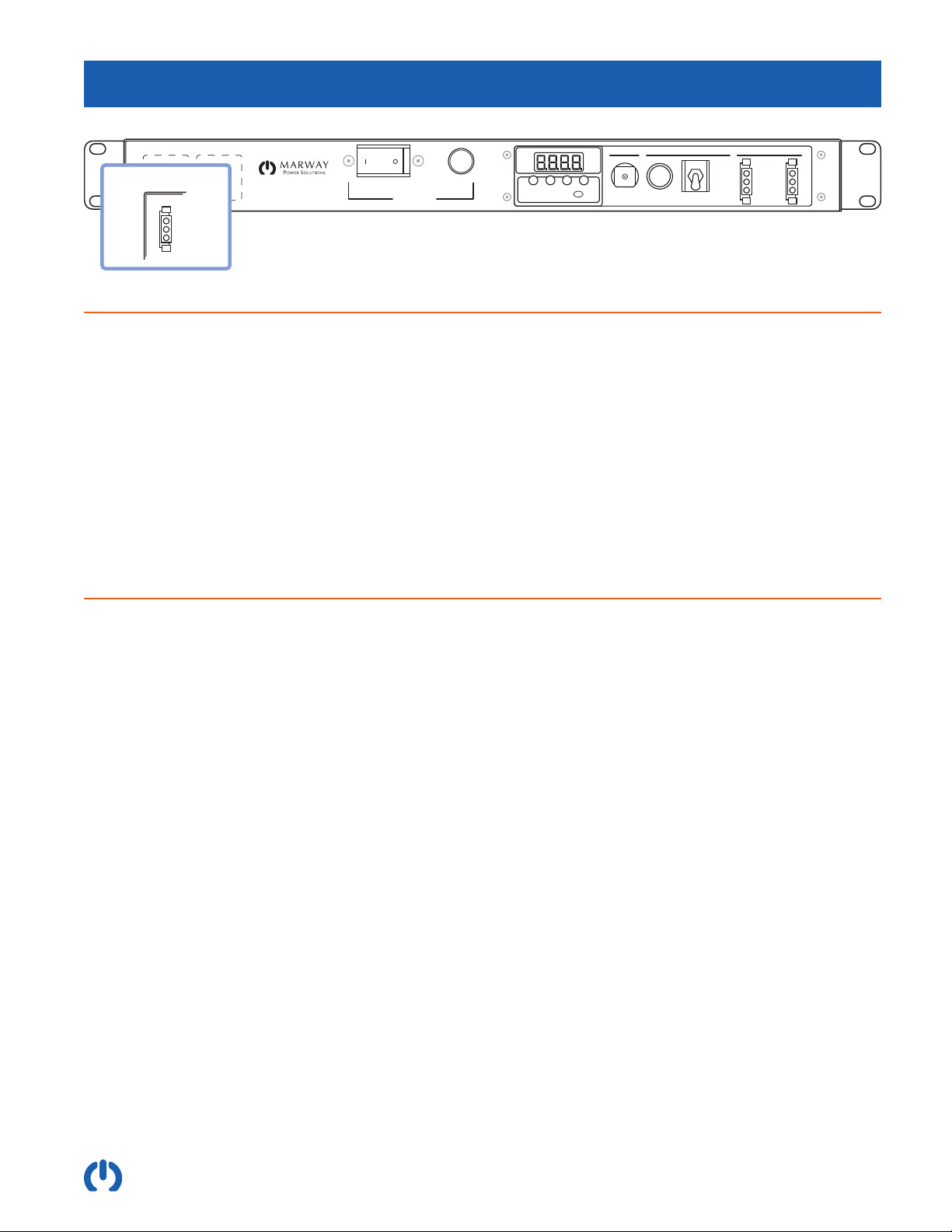
3.2.3 Controls Breaker
There is a small pop-out breaker protecting the control system components. This isn’t used during normal operation. If it
were to pop out, try pressing it back in. If it fails to stay in, there may be failure in one of the controls which is shorted, or
is drawing excessive current. This would likely indicate the need for an RMA repair. Contact Marway support.
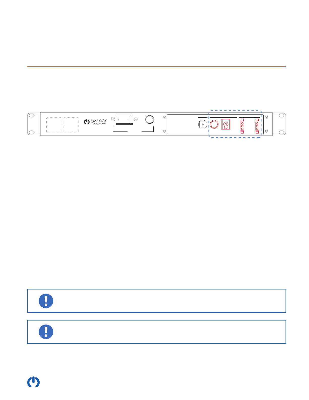
3.3 Remote Switching / EPO Option
The Remote Switching / EPO option includes the controls to interface to Marway’s Commander UCP 5000 Remote On/
Off/EPO panels and similar compatible panels. This panel is not required to operate the PDU. Refer to Marway’s Standard
Products Catalog for a list of the specic models which include this option.
PoweredBreaker
Outlet Control Bus
Enable
Disable
Return
Optima Main Breaker
Main Power
On
Switched OutletsControls
OFFON
PRESS
RESET
Local/On
Off
Remote
3.3.1 Remote Mode Switch
The Outlet Control Bus has a three-mode switch which is used as a local override to the overall remote command
system. The three modes are labeled Local/On, Off, and Remote.
When there is not a remote control panel connected:
• Local/On (up position) is the normal operating mode.
• Off (center position) causes an internal contactor to disengage power from all Group B and Groups C outlets. Group
A outlets continue to be powered. Therefore, Off disconnects power to almost all outlets even if the main breaker is
switched on.
• Remote (up position) will behave like Off.
When there is a remote panel connected to the PDU:
• Remote (down position) is the normal operating mode. Outlets are subject to the main breaker, and the upstream
remote panel On/Off/EPO controls.
• Local/On (up position) causes the PDU to ignore the On/Off/EPO commands of the remote panel. The main breaker
will then be in sole control of the outlets.
• Off (center position) causes an internal contactor to disengage power from all Group B and Groups C outlets. Group A
outlets continue to be powered. The PDU will ignore the On/Off/EPO commands of the remote panel. Therefore, Off
disconnects power to almost all outlets even if the main breaker is switched on.
If there will not be a remote On/Off/EPO panel connected to the PDU, switch the Outlet Control
Bus mode switch to the up position labeled Local/On. This is the normal operating position for any
unit with no remote panel. (The other positions will prevent power from getting to the outlets.)
Whether there is a remote control panel connected or not, toggling the Outlet Control Bus mode
switch to the center position labeled Off will disconnect power to Group B and Group C outlets.
Group A outlets will continue to be powered.