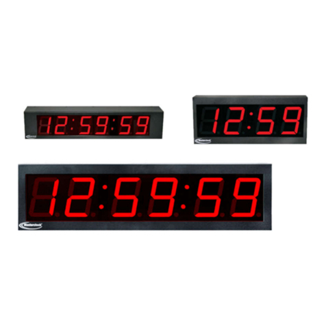
Masterclock CLKTCD12 User manual

CLKTCD12
TIME CODE
ANALOG CLOCK
(STEPPER MOTOR MOVEMENT)
USER MANUAL
Masterclock, Inc. Tel: 636-724-3666 Fax: 636-724-3776
2484 W Clay St, St Charles MO 63301
Masterclock, Inc 2006-2007

Disclaimer
The information contained in this document is subject to change without notice. Masterclock
®
,
Inc. (hereinafter Masterclock) makes no warranty of any kind with regard to this material,
including, but not limited to, the implied warranties of merchantability and fitness for a particular
purpose. Masterclock shall not be liable for errors contained here in or for incidental or
consequential damages in connection with the furnishing, performance, or use of this material.
See important limited warranty information at the end of this document.

Table Of Contents
Introduction......................................................................................................................... 1
Features............................................................................................................................... 2
Overview .................................................................................................................................................... 2
Configuration Methods............................................................................................................................... 2
Time Zone Offsets...................................................................................................................................... 3
Daylight Saving Time................................................................................................................................. 3
Pre2007 Standard – U.S.A. and Canada................................................................................................. 4
Post2006 Standard – U.S.A.................................................................................................................... 4
EU Standard – European Union ............................................................................................................. 4
Freewheeling Accuracy.............................................................................................................................. 4
TCXO and RTC circuit .......................................................................................................................... 4
Maintenance-free Rechargeable Battery................................................................................................. 4
Non-Volatile Configuration........................................................................................................................ 5
Clock Hand Calibration.......................................................................................................................... 5
Correction Behavior ................................................................................................................................... 5
Status LED ................................................................................................................................................. 5
Operating Environment .............................................................................................................................. 5
Installation........................................................................................................................... 7
Quick Start Information.............................................................................................................................. 7
Mounting .................................................................................................................................................... 8
Display Behavior........................................................................................................................................ 9
Configuration...................................................................................................................... 9
Configuration via Switches
.............................................................................................................. 10
Default Configuration
........................................................................................................................ 13
Reset Factory-Default Configuration ....................................................................................................... 13
Configuration Software (CLKTCD-Set) & USB Port........................................................................... 16
Troubleshooting Tips........................................................................................................ 24
SPECIFICATIONS........................................................................................................... 27
Input (time code) ...................................................................................................................................... 27
Communications – I/O ............................................................................................................................. 27
Power Requirements AC Model............................................................................................................... 27
Power Requirements DC Model............................................................................................................... 27
Internal Battery Circuit............................................................................................................................. 28
Physical .................................................................................................................................................... 28
Power Supply Component Characteristics ............................................................................................... 28
Operating/Storage Temperature & Humidity ........................................................................................... 28
OPTIONS – Special Order ....................................................................................................................... 28
Compliance............................................................................................................................................... 29
Limited Warranty............................................................................................................. 30
Exclusions ................................................................................................................................................ 30
Warranty Limitations................................................................................................................................ 30
Exclusive Remedies.................................................................................................................................. 30
APPENDIX A - Care of Polycarbonate Lens....................................................................a
APPENDIX B - Mounting.................................................................................................a
CLKTCD12 User Manual 1 © Masterclock
®
, Inc 2006-2007.
Rev 1.2.0 May ‘07 http://www.masterclock.com
INTRODUCTION
The CLKTCD12 is a precision analog clock containing a stepper motor drive and
advanced microprocessor controlled electronics to rapidly synchronize the hands on the
face of the clock to an accurate time code reference.
The clock has a built-in time code reader that can automatically detect forward running
longitudinal/linear SMPTE 24, 25, & 30 fps (frames per second) NDF (non-drop frame),
and IRIG-B (1 KHz modulated as well as un-modulated/pulse width modulated/DC level
shifted) time code formats.
SMPTE decoding supports 30 fps, 25 fps and 24 fps, NDF (non-drop frame). IRIG-B decoding supports the 1kHz
modulated format (B1) and the unmodulated format (B0).
SMPTE
Defined by the Society of Motion Picture and Television Engineers. It is available in frame rates of 30, 25,
and 24 frames second. The CLKTCD time code clock display supports all three formats.
*
All formats of
SMPTE time code decoded by the CLKTCD use the full date information in the user bits as defined by
Leitch Inc.
•
The CLKTCD, does not support decoding of SMPTE drop-frame time code. Masterclock, Inc.
does not provide products with, or support for, drop-frame capability.
IRIG-B
Defined by the Range Commanders Council, U.S. Army White Sands Missile Range. The format is
used by military, government, power industry, and many other commercial and industrial
applications. The CLKTCD decodes IRIG-B in both a 1kHz modulated (IRIG-B1) and unmodulated
(a.k.a pulse-width coded/DC level shifted) (IRIG-B0) format. All formats of IRIG-B time code
decoded by the CLKTCD use the time of year information BCD (binary coded decimal). All formats
of IRIG-B time code decoded by the CLKTCD also use the extended year/date and time zone
information in the control functions (CF) as defined by the IEEE 1344 specification. SBS (Straight
Binary Seconds) information is not decoded. Manchester format/encoding is not supported.
The CLKTCD12 can be configured for worldwide time zone offset and automatic
Daylight Saving Time (DST) adjustment and allows for reliable, accurate, and
maintenance free operation. Utilization of the automatic DST feature requires that the
clock be enabled to accept the time code date encoding using either the DIP switches (TC
control) or via the USB software configuration utility; and the time code source must
provide date encoding in the control bits/fields to the Masterclock/Leitch date encoding
standard for SMPTE or the IEEE-1344 year encoding for IRIG-B.
DST supportedTIME CODE
FORMATS
Masterclock/Leitch
Date Encoding
IEEE - 1344
Year Encoding
SMPTE – 30 fps
•
SMPTE – 25 fps (EBU)
•
SMPTE – 24 fps (FILM)
•
IRIG-B* pulse width modulated
•
I
N
P
U
T
S
IRIG-B(1)* amplitude modulated
•

CLKTCD12 User Manual 2 © Masterclock
®
, Inc 2006-2007.
Rev 1.2.0 May ‘07 http://www.masterclock.com
FEATURES
The Masterclock CLKTCD12 clock includes a USB interface and CLKTCD-Set
configuration management software for configuration, upgrade and maintenance.
This feature allows the device to be adapted to changing standards related to time
code or daylight savings. Additional features include:
Overview
• Time zone offsets (to one second resolution) supports any biasing requirements
• Complete flexibility in daylight saving time (DST) configurations
• Rechargeable maintenance free battery retains time in RTC (real time clock) for
minimum of two weeks of power loss or storage.
• Temperature compensated crystal oscillator (TCXO) for +/- 1 min year accuracy
when freewheeling.
• Universal AC power (90-264 VAC, 47-63 Hz), IEC power cord
• DC power input – available option
• All configuration settings retained in non-volatile flash memory
• Automatic setting of hands for maintenance free operation
• Second Hand with Sweep or Step optional run modes.
• Self-correcting after loss of power and/or time code reference and DST changes.
• Rapid hand correction using fast mode.
• Status LED on clock face, (located at 6 o’clock position).
Configuration Methods
The CLKTCD series of network clocks can be configured using one of the following:
• DIP Switches (default)
• USB port and Windows software application provided with your clock
Consult the section entitled Configuration for details on how to adjust settings through
the aforementioned mediums.
Basic operation of the CLKTCD series analog clocks is configured via the DIP
switches. This is the default mode. Optionally, the CLKTCD-Set configuration
software for Windows, supplied with the clock, may be used for advanced
configuration.
Note: If the configuration software is utilized to configure the clock, the switch
settings will be ignored or over-ridden. In order to restore the configuration mode to
the use of the DIP switches, the unit must be RESET to the factory default mode.
Please see the section regarding RESET the factory default mode. A RESET to
factory default configuration will enable the reading of the DIP switches and any

CLKTCD12 User Manual 3 © Masterclock
®
, Inc 2006-2007.
Rev 1.2.0 May ‘07 http://www.masterclock.com
previous software configuration settings will be need to be reconfigured. Only one
configuration method should be used at a time.
Time Zone Offsets
All time code analog clocks maintain time as UTC (sometimes equated with GMT)
internally.
[Note: If the time code being input into the CLKTCD is not UTC/GMT, i.e. it is already
offset for local time zone and/or DST, then do not adjust the time zone and/or DST
offset].
A time zone offset (or bias) can be provided to adjust the time for display purposes. A
bias can be set as a positive (+) offset indicating that the unit leads the UTC time, or
negative (-) offset value indicating the unit lags UTC time. An offset with a resolution of
one half hour (via Switches) or 1 second (via software configuration) can be achieved.
Factory default: no offset.
It is highly suggested to utilize a time code source with UTC reference and configuring
the offsetting for your time zone and DST in your local time display clock.
Daylight Saving Time
An automatic daylight saving time (summer time for European Union) adjustment can be
configured separately and in addition to a time zone offset.
[IMPORTANT NOTE: The incoming time code must have a date encoded in a format
recognized by the CLKTCD12 for daylight savings time adjustments to be performed.
For best reliability Masterclock recommends a time code source that encodes full date
information, such as the Masterclock GPS200A time code generator.]
For SMPTE time codes, date must be encoded to the Leitch specification. IRIG-B date
decoding is supported for the IEEE 1344 standard. Masterclock, Inc. master clock
systems also supports these specifications.
[Note: If your time code source is already making adjustments for Daylight Savings
Time, do not enable this feature.]
[Note: to utilize the automatic DST feature, the time code date encoding must be
enabled either by switches (TC control) or via the software configuration utility.]

CLKTCD12 User Manual 4 © Masterclock
®
, Inc 2006-2007.
Rev 1.2.0 May ‘07 http://www.masterclock.com
Daylight time standards vary widely throughout the world. The analog clock provides
flexible configuration options supporting most world daylight time standards.
Pre2007 Standard – U.S.A. and Canada
Traditional US/Canada daylight/summer time is configured as one (1) hour
positive bias. For the U.S. (thru 2006) and Canada, daylight savings time begins
on the first Sunday of April at 2:00AM (Local Time) and ends on the last Sunday
of October at 2:00AM (Local Time).
Post2006 Standard – U.S.A.
On August 8, 2005, the Energy Policy Act of 2005 was signed. This Act changed
the time change dates for Daylight Saving Time in the U.S, effective in 2007.
Starting in 2007, DST will begin on the second Sunday of March at 2:00 AM
(Local Time) and end the first Sunday of November at 2:00 AM (Local Time).
[Note: this new DST standard is currently only for the United States of America.
The US/Canada Standard pre2007 should continue to be used for Canada.]
EU Standard – European Union
In the European Union, daylight change times are defined relative to the UTC
time of day instead of local time of day (as in U.S.). For the European Union,
Summertime period begins at 1:00 AM UTC, and ends at 1:00 AM UTC.
European customers, please carefully consult the section entitled Device Settings
for details on setting daylight time.
Note: To ensure proper hands-free year-around operation, daylight time adjustments must
be configured using the daylight time option and not with the time zone offset option.
Factory default: daylight savings time is disabled. Decoding of the Date encoding in
time code is also disabled by default. You must enable and configure the settings.
Freewheeling Accuracy
The CLKTCD has built-in provisions to allow the clock to freewheel and maintain
accuracy for extended periods in the absence of time code. These features also allow the
unit to be set manually and run without time code with precision.
TCXO and RTC circuit
The CLKTCD contains a precision TCXO ( temperature compensated crystal
oscillator) and RTC (real time clock) circuit allowing the clock to maintain an
accuracy of +/- 1 minute per year to the last known time code input (+/- 165 mS
per day) when time code is not preset or cannot be decoded [freewheeling mode].
Maintenance-free Rechargeable Battery
The RTC and TCXO are maintained continuously from a rechargeable battery
circuit during periods of power outage. Minimum holdover period is two weeks

CLKTCD12 User Manual 5 © Masterclock
®
, Inc 2006-2007.
Rev 1.2.0 May ‘07 http://www.masterclock.com
once the battery is charged. The battery will automatically charge when the unit
is next powered and requires no maintenance.
Non-Volatile Configuration
The user’s configuration settings are maintained in non-volatile memory allowing the
current settings to be retained during power outages and brownouts.
Clock Hand Calibration
The clock hand positions are calibrated at the factory and maintained
continuously in non-volatile memory.
Correction Behavior
Upon a change to either the internal time reference caused by the acquisition time code,
shift of incoming time code, power loss, or from configuration changes to time zone
offset, daylight saving time, or entry into/from daylight savings time will cause the clock
to enter a correction/adjustment cycle.
This correction cycle may take up to 20 minutes to complete, depending upon the
location of the hands and the internal reference time at startup. During this time period
the hands will move rapidly in either a clockwise or counter clockwise motion. This is
normal operation for the clock during the correction/adjustment cycle.
Status LED
The red LED on the CLKTCD12 clock face (located at the 6:00 o’clock position) will
indicate its status:
LED STATE STATUS INDICATION
OFF The clock acquired valid time code and has synchronized its internal
real time clock to the time code reference. The internal clock time
(RTC) is considered accurate. The clock hands may be
adjusting/correcting rapidly either clockwise or counter-clockwise
during a correction.
ON SOLID The clock is not able to decode the time code source or the source is
not present. Time displayed on the face of the clock is based upon
internal time reference [RTC (real time clock) and TCXO
(temperature compensated crystal oscillator), and should not be
considered accurate. Check your time code source.
Operating Environment
The CLKTCD12 is an electronic device designed for indoor use, 0-50°C, and 0-90%
relative humidity. It is not water or moisture proof. Treat it as you would any other
delicate electronic device and do not expose it to water, excessive heat or physical abuse.
The AC version of the CLKTCD12 is designed to operate on 90-240VAC/47-63 Hz.

CLKTCD12 User Manual 6 © Masterclock
®
, Inc 2006-2007.
Rev 1.2.0 May ‘07 http://www.masterclock.com
The DC version (special order option) is designed to operate on 24VDC (nominal)
regulated or, 18-28 VDC power supplies. Please see the special order options or contact
sales@masterclock for details.

CLKTCD12 User Manual 7 © Masterclock
®
, Inc 2006-2007.
Rev 1.2.0 May ‘07 http://www.masterclock.com
INSTALLATION
Quick Start Information
Note: The hands of the CLKTCD12 cannot be set manually. Do not attempt to open
the clock to access the hands. This action will violate your warranty. This device has no
user serviceable parts inside.
The position of the hands has been factory calibrated and is retained in non-volatile
memory. This factory calibration of the hands makes it unnecessary to set the hands of
the CLTCD12 clock.
If for any reason the clock hands become slightly out of alignment, a calibration setting
function has been provided.
• Apply power
Insert the power cord.
AC models will require an IEC power cord.
DC models will require a 24 VDC (18-28 VDC) regulated power supply.
After application of power the CLKTCD12 will go through an internal checkout.
Time from the battery backed real-time clock circuit will be applied until the
clock decodes a valid time code signal. The battery circuit for the real time clock
and configuration settings is a rechargeable circuit with a minimum holdover of
two weeks.
Note: the time from the circuit may be invalid if the battery circuit has
become discharged.

CLKTCD12 User Manual 8 © Masterclock
®
, Inc 2006-2007.
Rev 1.2.0 May ‘07 http://www.masterclock.com
The red status LED located at the 6 o’clock on the face will be solid ON until a
valid time code signal is decoded, (or if the signal has been lost). This represents
normal operation when time code is not present or cannot be decoded.
The clock will correct the hands in a rapid mode, either forward (clockwise) or
backward (counter-clockwise). This represents normal operation when correcting.
• Configure the clock’s time zone offset, DST offset, and time code input type using
one of the two available methods described in the Configuration section.
• Apply time code.
Attach a 50 Ω(Ohm) coaxial cable (typically RG58), from a valid time code
source, to the BNC connector on the rear of the unit.
Once the clock has locked to the valid time code source and adjusted its
internal RTC (real time clock) the red status LED will be OFF. This
represents normal operation when locked to time code.
The clock hands will automatically adjust or correct by rapidly rotating
in either clockwise or counter-clockwise direction during a correction
cycle. This may take up to 20 minutes, depending upon the location of
the hands at the start of the cycle. Once the hands have stopped moving
rapidly, they represent the current local time of the clock [as reference
to the time code input + any offsets that have been configured]
• Verify the time displayed by the hands is what you expected.
• Complete the installation by mounting the clock to the wall using the
included mounting bracket.
Mounting
The CLKTCD12 is designed for surface mounting on a wall using the attached mounting
bracket.
The bracket is designed to fit either a standard 2”x 4” or 4” x 4” conduit box. Remove
the retaining screw from the top of the clock to remove the bracket. Mount the bracket on
the wall/conduit box and attach the power & signal cables, secure the clock to the bracket
using the retaining screw.
Power and/or low voltage signal wiring should be provided and installed according to
local electrical codes to access the clock from the rear.
Caution: Do not route power or signal cables between the case and the wall (along
the exterior of the wall), which may pinch or fray the power or signal cable and
create a hazardous condition.

CLKTCD12 User Manual 9 © Masterclock
®
, Inc 2006-2007.
Rev 1.2.0 May ‘07 http://www.masterclock.com
Display Behavior
The CLKTCD12 may take up to 20 minutes to set the time, depending on the current
internal [local] time and the hand positions. If the CLKTCD12’s hands do not move to
the correct time within 20 minutes, check the section of the user manual entitled
Troubleshooting Tips.
CONFIGURATION
The CLKTCD12 maintains its configuration data in non-volatile flash memory allowing
the unit to retain configuration settings even when power is off. The CLKTCD12 may be
configured by either DIP switches or via software control using the USB port and
software configuration utility.
The CLKTCD12 ships from the factory with all switch/ software configuration offset
options in the OFF setting, in order to display UTC time.
[Note: the CLKTCD12 interprets the incoming time code as UTC.]
Factory default configuration:
o Time Zone offset – disabled - no offsets applied
o Daylight Saving Time - disabled – no DST adjustment
o Time Code Date/Year Encoding – disabled
o Second Hand Motion – Sweep mode
o Configuration Mode - Read from current DIP Switch settings

CLKTCD12 User Manual 10 © Masterclock
®
, Inc 2006-2007.
Rev 1.2.0 May ‘07 http://www.masterclock.com
Configuration via Switches
Basic operation of the CLKTCD12 is configured via the DIP switch banks accessible on
the left hand side of the rear electronics cover.
The switch bank configures fundamental operation as follows:
Switch bank 1 configures Time Zone Offset & Daylight Savings Time
Switches S1-1, S1-2, S1-3, & S1-4: Time zone hour offset:
Hour offset S1-1 S1-2 S1-3 S1-4
0 hour offset OFF OFF OFF OFF (default)
1 hour offset ON OFF OFF OFF
2 hour offset OFF ON OFF OFF
3 hour offset ON ON OFF OFF
4 hour offset OFF OFF ON OFF
5 hour offset ON OFF ON OFF
6 hour offset OFF ON ON OFF
7 hour offset ON ON ON OFF
8 hour offset OFF OFF OFF ON
9 hour offset ON OFF OFF ON
10 hour offset OFF ON OFF ON
11 hour offset ON ON OFF ON
12 hour offset OFF OFF ON ON
Switch S1-5: Additional ½ hour time offset (as set by switch positions 1-4).
Function S1-6
No ½ hour offset OFF (default)
Enable ½ hour offset ON

CLKTCD12 User Manual 11 © Masterclock
®
, Inc 2006-2007.
Rev 1.2.0 May ‘07 http://www.masterclock.com
Quick Reference Guide
Time Zone & DST Switch Settings for US/Canada
US/Canada Standard Pre 2007
US Standard Post 2006
Switch S1-6: Negative/Positive time zone offset (as set by switch positions 1-4 & 5).
Function S1-5
Time offset is negative OFF (default)
Time offset is positive ON
Switch S1-7 & S1-8 : Daylight saving time adjustment. (See Daylight Saving Time)
Function S1-7 S1-8
DST adjustment disabled OFF OFF (default)
US/Canada DST enabled ON OFF (US standard thru Fall 2006)
US DST enabled OFF ON (new US standard - Spring 2007)
EU DST enabled ON ON (European Union)
[IMPORTANT NOTE: The incoming time code must have a date encoded in a format
recognized by the CLKTCD12 for daylight savings time adjustments to be performed.
And the time code date encoding Switches S2-1 and S2-2 must be set to enable the
decoding of these control bits/fields]

CLKTCD12 User Manual 12 © Masterclock
®
, Inc 2006-2007.
Rev 1.2.0 May ‘07 http://www.masterclock.com
Switch bank 2 configures how Time Code Control Bits/Fields are handled, special
operation modes of the clock.
Switches S2-1 & S2-2: Time code Control Bits or Control Fields
Hour offset S2-1 S2-2
No additional encoding OFF OFF (default)
IRIG 1344 & SMPTE Leitch ON OFF
Reserved for future use OFF ON
Reserved for future use ON ON
Switch S2-3: This switch is currently undefined & reserved for future use
Function S2-3
Reserved OFF (default)
Reserved ON
Switch S2-4: This switch is currently undefined and reserved for future use.
Function S2-4
Reserved OFF (default)
Reserved ON
Switch S2-5: This switch is currently undefined and reserved for future use.
Function S2-5
Reserved OFF (default)
Reserved ON
Switch S2-6: Set the second hand motion mode
Function S2-6
Sweep (continuous) OFF (default)
Step (pulse) ON
Switch S2-7: Calibrate hands to position. Used in conjunction with S2-8 “ON” to set the
clock hands
Function S2-7
Set to 12:00:00 OFF (default)
Set to 6:00:00 ON
Switch S2-8: Used in conjunction with S2-7 to set the clock hands
Function S2-7
Run OFF (default)
Set ON

CLKTCD12 User Manual 13 © Masterclock
®
, Inc 2006-2007.
Rev 1.2.0 May ‘07 http://www.masterclock.com
[Note: The CLKTCD12 will accept switch changes dynamically. It is not necessary
to restart or cycle the power of the CLKTCD12 for the device to accept the new
settings]
[Note: Once the clock has been configured with the CLKTCD-Set software, the
switch settings will be over-ridden; and the unit will ignore all switch settings unless
a RESET Factory Default is performed.]
Default Configuration
The CLKTCD12 ships from the factory with all S1 switches in the OFF position. This
default configuration results in the time displayed as:
Time zone offset: None
Daylight Saving Time: Disabled
Time Code Date Encoding Disabled
Reset Factory-Default Configuration
In some situations it may be necessary to return the CLKTCD12 to its factory default
configuration. A RESET to factory configuration is accomplished by pressing
button combination (B1 and B3) simultaneously. These buttons are located on the
electronics cover on the rear of the CLKTCD12 network clock chassis. Buttons B1,
B2 and B3 are also used to calibrate the hands of the clock.
To reset configuration to factory default –
1. Remove AC or DC power from the device,
2. Depress and hold both button B1 [CW/Forward] and button B3
[Trim/Forward] button simultaneously.
3. Apply power to CLKTCD12 and continue holding the reset button
combination down for 5 seconds.
4. The time code clock configuration will now be reset, and the unit will default
to using the current switch positions. If special configuration was applied via
the software configuration tool, then the unit will need to be reconfigured.

CLKTCD12 User Manual 14 © Masterclock
®
, Inc 2006-2007.
Rev 1.2.0 May ‘07 http://www.masterclock.com
Hand Calibration
[Note: The CLKTCD12 analog clock hands have been pre-set and aligned at the
factory. This hand location and alignment information is retained in non-volatile
flash.]
[Note: Under normal operating circumstances it should not be necessary to adjust
or align the hands. However, if for any reason, the hands are not tracking the time
code source, an adjustment function has been built into the CLKTCD12]
[Note: The visual determination of the accuracy of the hand display should be done by
comparing the clock hands only after the CLKTCD12 indicates that it is synchronized to
time code, and then only to a digital display or other reference that has also been locked,
preferably to the same time code source. The reference display should be set adjacent to
the CLKTCD12 unit and eye movements should be minimized when doing comparisons.
Please see the troubleshooting section for additional information/suggestions. ]
To adjust the hands:
Select the “ Set “ position for switch S2-8, the unit will enter the adjustment mode; the
hands of the analog clock will stop.
1. Select the “Set” position for switch S2-8 (ON),
2. Select either the 12:00:00 (OFF) or 6:00:00 (ON) position using switch S2-7
3. Depress and release either button B1 [CW/Forward] or button B2
[CCW/Reverse] button to move the hands in the desired direction for either
12:00:00 o’clock or 6:00:00 o’clock.
[Note: After releasing the button, the hands will rotate in the desired
direction until any button is pressed. This feature allows for easier
setting of the hands]
4. Depress and Hold button B1 or B3 down for 10 seconds to advance rapidly.
Then release. The hands will rotate rapidly until any button is pressed.
[Note: This feature allows for rapid setting of the hands]
5. Stop the hands a few seconds before the desired position.
6. Fine-tune the second hand position to the center of the 12-indicator mark by
pressing the Trim/Forward button B3 to move the second hand in the forward
direction incrementally.
[Note: this function only works in the forward or clockwise direction]

CLKTCD12 User Manual 15 © Masterclock
®
, Inc 2006-2007.
Rev 1.2.0 May ‘07 http://www.masterclock.com
7. Verify the final hand positions.
Set to 12:00:00: Set to 6:00:00
All hands hour, minute, & second Hour hand points to center of 6
point to center of 12 tic mark mark; minute & second hands
point to center of 12 tic mark
8. Change SW2-8 to “Run” mode (OFF).
The new hand alignment settings will be stored in non-volatile flash. The clock hands
will adjust to the new settings and will continue displaying the time after several
moments.
[Note: it is suggested to double check the new settings with the digital display reference
at this point to ensure that the hands have been correctly set]

CLKTCD12 User Manual 16 © Masterclock
®
, Inc 2006-2007.
Rev 1.2.0 May ‘07 http://www.masterclock.com
Configuration Software (CLKTCD-Set) & USB Port
A USB type B port has been included on the rear cover of the clock to provide a means of
configuring the clock via software; and to allow for firmware upgrades for either
firmware corrections or future product enhancements.
To utilize the USB port, connect a USB type A to USB type B cable from the computer
to the clock.
USB-A cable end (to computer) USB-B cable end(to clock) USB-B port on clock
A software configuration program, CLKTCD-Set, along with USB drivers has been
provided with the clock.
Installing USB drivers:
Once the clock is powered, the Windows Plug and Play manager will detect a new USB
device – Masterclock USB device – and request drivers.
Insert the driver/software CD that was included with your clock.
Browse to the drivers directory and select OK.
This software is compatible with Windows
98SE/ME/2000/XP and also Windows
2003 server operating systems.
To install the software program on your server/workstation/PC, complete the following
steps:
1. Insert the software CD that shipped with your clock.
2. Run the ‘setup.exe’ application from the diskette. By default, the setup utility
will suggest installing files to C:\Program Files\Masterclock\CLKTCD.
(Another path may be selected if desired.)
Open the software program by clicking the shortcut in your start menu. Other
methods should not be used to manage the clock while using the software.

CLKTCD12 User Manual 17 © Masterclock
®
, Inc 2006-2007.
Rev 1.2.0 May ‘07 http://www.masterclock.com
Main Window
Each clock can be configured to display local time, using time zone offsets and DST
settings. These offset changes are made relative to UTC time. The clock always
interprets the incoming time code as UTC.
The top left section of the main window shows the firmware version and serial
number of the clock. Located below this information is the current status of the
clock display, this information is constantly updated. The Local Time is the time
displayed on the clock face, including any time zone, or DST offset information.
The UTC Time is the internal time reference derived from the incoming time code
and treated as UTC. This display update is not precise, but is meant to give you a
view of the clock display time for basic troubleshooting and maintenance purposes.
Also included is a Time Code Status which displays the type of incoming time code
&/or the synchronization status.
The Time Zone and Daylight Saving Time buttons, included in the right half of the
window, give the clock complete flexibility to set and display any time zone and
worldwide DST combination.
Time Zone Offset
Modify the time zone by first clicking the Time Zone button. This opens a new
window that gives you a list of time zones, including descriptions to help with the
selection. Select the desired time zone and click OK to close the window. Changes
are applied when you click OK.
Table of contents
Other Masterclock Clock manuals