Matelec FSA-60000 User manual

240Vac c/w 3V DC Battery Backup
Photoelectric Smoke Alarm
Product Code: FSA-60000
Thank you for purchasing a MATelec Australia Smoke Alarm.
Please read this user’s manual thoroughly to familiarise yourself with the operation of the
smoke alarm before use.
1
Product specifications
Sensing Type Photoelectric (Type A -
contains no radioactive
material)
Power Supply 220-240V AC 50Hz
Back-up Battery
(Power Supply)
Replaceable DC 3V
battery: CR17450
10 year backup Lithium
Interconnectivity Hard wired OR Wireless
Module, FSA-50000
(supplied separately)
Interconnection Maximum 24 paired
alarms
Max wiring length
between first
and last alarm: 150 m
Size o135mm x 45mm
Temp Range 0°C - 45°C
Max Humidity 93%RH
“Alarm Signal
Pattern” ISO 8201
Alarm Volume 85dB at 3m
Hush Time 10 mins
Compliance AS 3786: 2014
Certification CSIRO Verification
Service
Distributor
MATelec Australia
Address: 5 Telford Drive, Shepparton VIC 3630
Postal Address: PO Box 7093, Shepparton VIC 3632
Phone: 1800 281 282
Fax: 1300 281 282
Email: info@matelecaustralia.com.au
Important Information
This smoke alarm MUST be installed in
accordance with national and local council
building regulations, state fire department
requirements and the latest edition of the
Australian and New Zealand wiring Rules AS/
NZS 3000. Building codes and regulations
may vary from each state jurisdiction.

NOTE: this information serves as a guide only.
Ensure units are located and installed as per
your local building codes and regulations.
1. As a minimum, smoke alarms should
be located between sleeping areas
and potential sources of fire such as a
kitchen, heater or basement. In single
story homes with one sleeping area,
an alarm should be installed in the
hallway outside the room. In single
story homes with two or more sleeping
areas, a minimum one alarm for each
area is required. In multilevel dwellings,
an alarm should be installed outside
and inside each sleeping area, in the
basement, and on every level of the
home.
2. Wherever possible Smoke alarms should
be installed on the ceiling and as close
to the centre of the room as possible.
(Avoiding dead air spaces, an area
in which trapped hot air will prevent
smoke from reaching the alarm).
(Diagram 1).
Smoke alrms should not be placed
within:
• 300mm of a corner of a ceiling
and a wall
• 300mm of a light fitting
• 400mm of an air-conditioning vent
• 400mm of the blades of a ceiling
fan.
3. Larger rooms, in excess of 10m in length,
should have multiple alarms installed.
4. For buildings with a peaked, or
cathedral type ceiling, the alarm musty
be installed at least 50cm from the apex
(Diagram 2).
5. Smoke alarms must be paired
(interconnected) with every other
smoke alarm in the residence so they all
activate together.
Avoid these locations
Smoke Alarms are sensitive electrical
equipment by nature.
To reduce the likelihood of nuisance or
repetitive false-triggering smoke alarms, avoid
installing:
1. Near cooking appliances, or close
to heating and cooling vents or
appliances.
2. In dusty or dirty areas.
3. In areas of excessive heat (eg, Garage)
4. In areas subjected to relative humidity
outside the range of 10%-93% eg
bathrooms, laundries.
5. Avoid installing where bugs or insects
are present.
Install locations
4”
(10cm)
Minimum
12”
(30cm)
Minimum
12”
(30cm)
Minimum
CEILING
SIDE
WALL
NOT IN
THIS AREA
ACCEPTABLE HERE
BEST HERE
DIAGRAM 1
50cm NOT
IN THIS
AREA
DIAGRAM 2
DO NOT INSTALL
100cm
ANYWHERE IN
THIS AREA
DEAD AIR
4”
(10cm)
Minimum
12”
(30cm)
Minimum
12”
(30cm)
Minimum
CEILING
SIDE
WALL
NOT IN
THIS AREA
ACCEPTABLE HERE
BEST HERE
DIAGRAM 1
50cm NOT
IN THIS
AREA
DIAGRAM 2
DO NOT INSTALL
100cm
ANYWHERE IN
THIS AREA
DEAD AIR
2
1. Remove the battery tab.
2. Complete wiring termination as per
wiring diagram.The Green LED will
illuminate once power is connected.
3. Place the bracket in the desired /
recommended location and mark
mounting holes. Mount the unit using
the fixings provided.
NOTE: All interconnected units must be
supplied from a single power circuit.
(Hardwired interconnection must not be
made across more than one circuit)
Installation

3
Test Procedure
Hardwired Interconnection
1. Ensure the GREEN LED remains on, on
each unit. (This indicates 240V mains
AC power is connected)
2. Pressing and holding the TEST button on
any smoke alarm for at least 5 seconds
will cause unit to ALARM and the RED
LED to flash.
NOTE: all other interconnected smoke
alarms will stop alarming when releasing the
TEST button, and the RED LED will flash for 3
minutes.
3. Repeat this procedure for each alarm.
NOTE:The sending/test unit will only ALARM
on initial pressing, not in unison at same time
as receiving units.
NOTE: Smoke alarms CANNOT be HUSHED
while in TESTING mode. When replacing
battery, ensure unit is tested afterwards to
confirm correct operation.
Use minimum of 1mm2250V insulated wire for all wiring including inter-connecting.
Wiring instructions
1. All interconnected alarms must be connected to the same sub/circuit
2. A common Neutral must be used for interconnect to function
3. Do not connect the interconnect wires to Active or Neutral.
• The green LED remains illuminated
when the unit is connected to mains
power.This should always be on.
• In standby mode, the red LED will flash
(very faintly) periodically to indicate
that the unit is operating correctly.
• When smoke is detected, the unit will
sound a loud audible alarm, and the
red LED will flash continuously. The
alarm will silence once the presence of
smoke is removed
Operation
Wiring Instructions:
TERMINAL:
L : Active wire
N : Neutral wire
I/O : Interconnect wire
(when applicable)
E/LOOP : No wire
A
E-Loop
N
I-Connect
A
E-Loop
N
I-Connect
A
E-Loop
N
I-Connect
A
E-Loop
N
I-Connect
220-240V a.c.
Active (A)
Neutral (N)
TERMINAL
I-Connect : Interconnection
N : Neutral
E-Loop : No wiring
A : Active
150 meters maximum between first and last interconnected smoke alarm
If more than one smoke alarm is installed all
units must be interconnected or paired.
Interconnection can be achieved either by
wiring the I-Connect terminals of the alarms
together or pairing using the optional
FSA-50000 wireless module (not included).
NOTE: Matelec Australia smoke alarms must
not be interconnected with any other brands
of smoke alarms or products & components.
Doing so will void warranty.
Interconnection Requirement

Reset Wireless Module to
factory default setting
1. Disconnect mains power and unhinge
unit from base
2. Remove the battery.
3. Press and hold the TEST button while
reinserting the battery. (RED LED on
smoke alarm FACE will illuminate for 3
seconds.)
4. When the RED LED turns off, release the
TEST button. (The RED LED will illuminate
again for 3 seconds.) During these 3
seconds, press the TEST button ONCE
to UNPAIR and RESET the smoke alarm.
The alarm will CHIRP once and then 3
consecutive times.This indicates the
smoke alarm has been returned to its
original factory state.
4
NOTE: Smoke alarms should be paired before
mounting/installation.
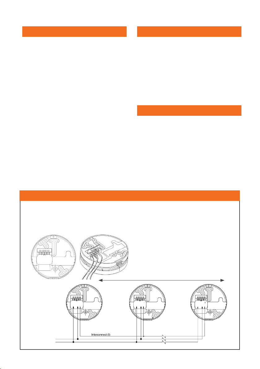
1. Remove the blank module, replacing
with Wireless Module (FSA-50000). Unit
will CHIRP 3 times, signifying succesful
initiation.
2. Select a smoke alarm to be the MASTER
unit. Use the MASTER sticker provided
or mark this smoke alarm for ease of
adding additional SLAVE smoke alarms
in future.
(NOTE – The MASTER unit should be the
smoke alarm that is to be installed in the
central part of the residence.When using a
combination of wireless and wired smoke
alarms, it is recommended a centrally
located,WIRED smoke alarm be selected as
MASTER)
3. Press the TEST button on the MASTER
smoke alarm 3 times within 2 seconds
to enter “Pairing Mode”. (RED LED will
illuminate for 5 minutes)
4. The MASTER smoke alarm will now
search for any slave alarms to pair with.
(MASTER smoke alarm will exit pairing
mode after 5 minutes of inactivity. If
required, repeat step 4. to restart pairing
process)
5. On the SLAVE smoke alarm press the
TEST button 3 times within 2 seconds
to enter pairing mode. If pairing with
FSA-30000/s, the LED on FSA-30000 turns
GREEN for 3 seconds, and FSA-60000/s,
will CHIRP once.
Both indicates units have successfully paired.
The MASTER (FSA-60000) alarm LED will then
remain RED until another pairing request is
received within 5 minutes.
Repeat pairing process for any additional
SLAVE smoke alarms required.
NOTE: When all SLAVE smoke alarms have
been paired successfully, press and hold
the TEST button on the MASTER smoke alarm
for 3 seconds to exit pairing mode, or wait 5
minutes to automatically exit. (RED light will
extinguish)
NOTE: More SLAVE smoke alarms can be
added into smoke alarm network at a later
Wireless pairing (For use with Wireless
Interconnection Module)
date by repeating the pairing process but
must pair with previous MASTER smoke alarm.
Wireless Test Procedure
1. 1. Press and hold the TEST button on
any smoke alarm for at least 2 seconds
to test ALL smoke alarms.After a short
delay, all paired smoke alarms will
ALARM for 10 seconds. (FSA-30000 -
RED LED will flash on front face twice
a second for 5 minutes or until the
CONTROL button is pressed again.)
Check all smoke alarms are paired
correctly, this way.
NOTE: Smoke alarms CANNOT be HUSHED
while in TESTING mode.
NOTE: Smoke alarms CANNOT be TESTED
more than once in 5 minutes. (Units
commence recalibration in this time period).
Hush function
NOTE: If the alarm sounds, first ensure there
is NO DANGER. Do not assume it is a false
alarm. Carefully check residence for the
presence of smoke.
1. 1. While the unit is in ALARM mode,
pushing the HUSH button for 2
seconds will HUSH the smoke alarm
for approximately 10 minutes.The RED
LED will flash once every 8 seconds to
indicate the smoke alarm is running in
HUSH mode.
2. After 10 minutes the alarm will resume
normal operation. If the trigger source is
still present, the smoke alarm will ALARM
again.
FSA-50000

Audio-visual guide
OPERATION RED LED STATUS SOUND
Power Up Flash
No beep for
no wireless
interconnection.
No beep for
hard wired
interconnection.
Beep once when
wireless module is
installed & paired.
Chirp 3 times when
wireless module is
installed but NOT
paired.
Alarm
functioning
correctly
(standby)
Low intensity
1x flash every
40 seconds
-
Alarm Memory
Triggered alarm
Flashes
Twice every 20
seconds for 1
week
-
Low battery
warning
Flash every 40
seconds
One chirp every 40
seconds.
Press HUSH button
enter ‘Do Not Disturb’
Mode for 10 hours.
Fault warning Flash every 40
seconds
One chirp every 40
seconds. Press HUSH
button enter ‘Do Not
Disturb’ Mode for 10
hours.
Self-test fault
warning
Flashes twice
every 40
seconds
-
HUSH mode
Flash once every
8 seconds for
10 min
-
Do not Disturb
Flash once very
40 seconds for
10 hours
-
Smoke
detected on
local alarm
Flash every
second
Continuous alarm
signal pattern,
Press HUSH button
to enter Silent Mode
for 10 min. Initiate
emergency plan
Smoke
detected on
interconnected
or paired unit
-
Continuous alarm
signal pattern,
Press HUSH button to
enter Silent Mode for
10 min
Test function Flash every
second
Continuous alarm
signal pattern until
TEST button released
Weekly self-test Flash once Chirps once every
week
End of Life (10
year) Warning
Flashes once
every 40
seconds
Chips every 40
seconds
Cannot enter ‘Do Not
Disturb’ Mode.
5
Memory feature (on a
triggered smoke alarm)
In an interconnected network, the RED LED
on the triggered smoke alarm flashes TWICE
approximately every 20 seconds for 72 hours.
This can be used to identify the triggered unit
in the event that residence is unoccupied at
the time of an ALARM.
1. The HUSH function can be repeated as
many times as necessary.
NOTE: Where multiple alarms are
interconnected, the HUSH function WILL
NOT OPERATE EXCEPT ON THE UNIT THAT THE
ALARM WAS TRIGGERED FROM. The triggered
unit can be identified by the RED LED flashing.
Troubleshooting Guide
PROBLEM SOLUTION
Green LED not
illuminated
Check mains power
connection. If green power
light still not visible, perform
a reset of the unit: Remove
the battery, press Test button
twice, re-install battery.
Hard-wire
interconnected
smoke alarms
don't alarm
during test
Check if Smoke Alarms are
in same circuit, interconnect
cable is connected correctly
as per wiring diagram and
mains power is connected.
Wireless
interconnected
smoke alarms
don't alarm
during test
Check a wireless interconnect
module is inserted in all units
in network. Perform a reset
and re-pairing of units in the
network.
Alarms sound
for no apparent
reason
Always check for presence of
smoke in all locations first.
Check for presence of trigger
sources. See Trigger Source
guide for potential causes
and rectify as necessary.
Identify the alarm that was
triggered by the flashing RED
LED, press the Hush button on
this unit. (Unit will not silence
if it does not have a flashing
RED LED)
If the smoke alarm cannot
be hushed, open the Smoke
Alarm, and remove and
replace battery.
Perform reset and re-pairing
of network.
1x Chirp every
40 seconds and
cannot hush
Check if battery has been
installed correctly.
Replace battery.
Perform reset and re-pairing
of network.
If the above rectification steps do not rectify
the issue at hand, contact MATelec for tech
support.

Maintenance
Periodically use the Test Procedure to test the
smoke alarm.
Periodically clean the smoke alarm by
carefully vacuuming the outside of the unit
to remove any dust build up and wipe gently
with a damp cloth.
Do not spray any cleaning liquids directly
onto/into the smoke alarm.
If the low battery alarm sounds, replace
battery.
Test Smoke
Aerosol products, such as Smoke Alarm
Test Smoke, (Although Photelectric smoke
detectors are less susceptible to trigger
by this method) can be used to test the
integrity of smoke alarms by simulating smoke
conditions. If using an aerosol smoke alarm
Warranty
This MATelec Smoke Alarm is designed for
use in residential dwellings and is warranted
as such.
The FSA-60000 smoke alarm is warranted
for a period of 5 years, to be free of defects
in materials or workmanship, under normal
use. In the event of a warranty issue, please
contact MATelec Australia via email, at
info@matelecaustralia.com.au.
Please see the warranty card included with
the smoke alarm package, for full details of
the warranty.
Scan QR code
to view our video
series giving you
a comprehensive
understanding of
all technical and
installation aspects
of our Smoke
Detectors.
SCAN ME
6
Interconnect options
CONFIGURATION 1 - HARD-WIRED INTERCONNECTION, 1 CIRCUIT
Hard-wired
Interconnection
FSA-60000 FSA-60000
Circuit 1
CONFIGURATION 2 - WIRELESS INTERCONNECTION, 1 CIRCUIT
Wireless
Interconnection
Circuit 1
FSA-60000 with
FSA-50000 Wireless
Interconnection
Module
FSA-60000 with
FSA-50000 Wireless
Interconnection
Module
CONFIGURATION 3 - WIRELESS INTERCONNECTION ONLY, 2 CIRCUITS
Circuit 1 Circuit 2
Wireless
Interconnection
FSA-60000 with
FSA-50000 Wireless
Interconnection Module
FSA-60000 with
FSA-50000 Wireless
Interconnection Module
testing product, from a distance of 1-2 metres,
spray the can towards the smoke alarm for
2 seconds. Smoke alarms with built in time
delay circuitry may require additional spray to
trigger the alarm.
Excessive spraying at close range may
permanently affect the smoke alarm’s
sensitivity.
Table of contents
Other Matelec Smoke Alarm manuals