7
110 V UNITS
All Matrix 3x, 5x, 7xe and 7xi 110 V bikes require the use of
a 100-125 V, 60 Hz and a 15 A “Dedicated Circuit”, with a
non-looped (isolated) neutral/ground for power. This outlet
should be a NEMA 5-15R and have the same configuration
as the plug. No adapter should be used with this product.
These bikes can be daisy-chained together with up to 4 units
per 15 A dedicated circuit. Matrix daisy-chain cord adapters
are sold separately.
220 V UNITS
All Matrix 3x, 5x, 7xe and 7xi 220 V bikes require the use of
a 216-250 V, 50 Hz and a 15 A “Dedicated Circuit”, with a
non-looped (isolated) neutral/ground for power. This outlet
should be a NEMA 6-15R and have the same configuration
as the plug. No adapter should be used with this product.
These bikes can be daisy-chained together with up to 4 units
per 15 A dedicated circuit. Matrix daisy-chain cord adapters
are sold separately.
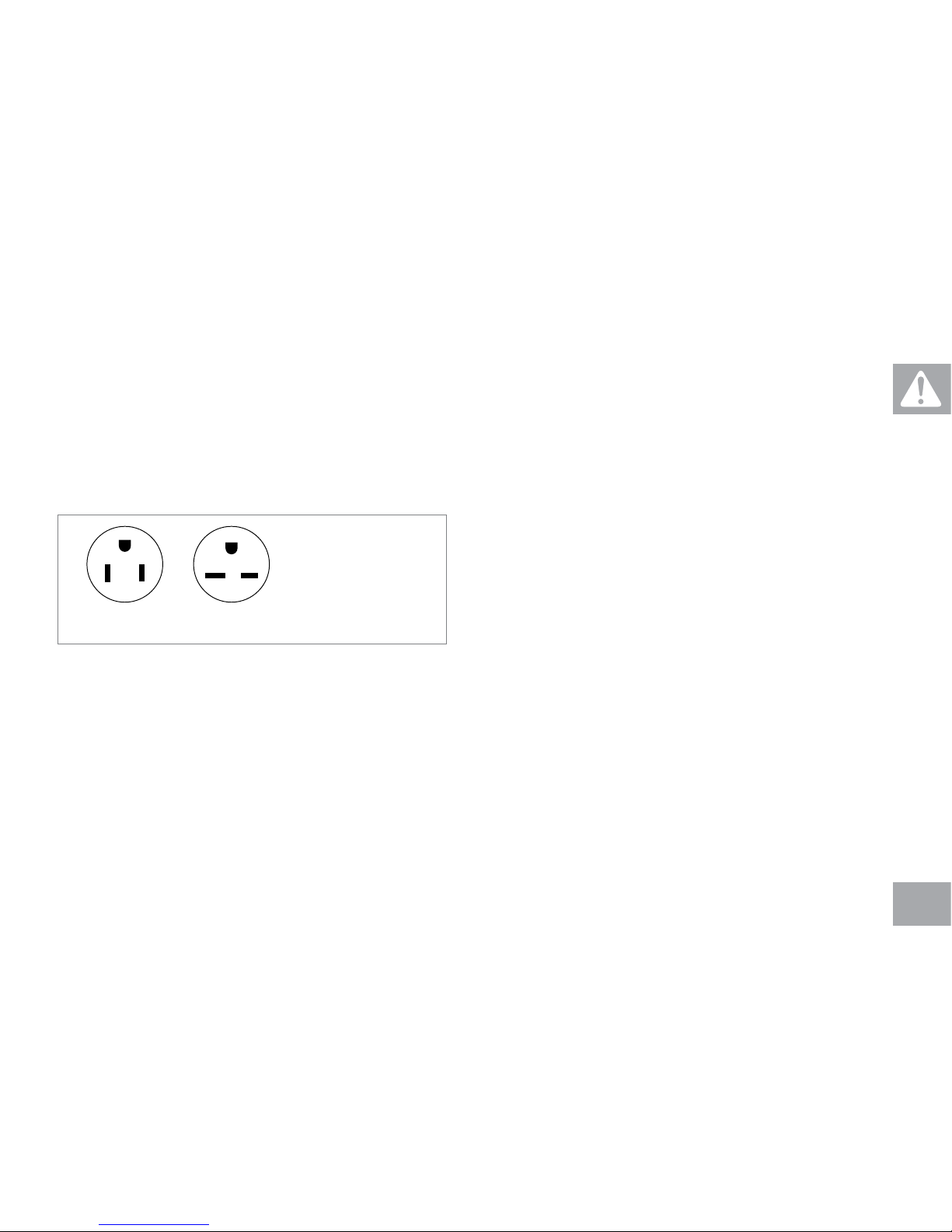
220 NEMA 6-15P
PLUG
110 NEMA 5-15P
PLUG
North American power cord
plugs shown. Depending on
your country, the plug type
may vary.
GROUNDING INSTRUCTIONS
The unit must be grounded. If it should malfunction or
breakdown, grounding provides a path of least resistance
for electric current to reduce the risk of electric shock.
The unit is equipped with a cord having an equipment-
grounding conductor and a grounding plug. The plug
must be plugged into an appropriate outlet that is
properly installed and grounded in accordance with all
local codes and ordinances. If the user does not follow
these grounding instructions, the user could void the
Matrix limited warranty.
ADDITIONAL ELECTRICAL INFO
In addition to the dedicated circuit requirement, the
proper gauge wire must be used from the circuit breaker
box, to each outlet that will have the maximum number
of units running off of it. If the distance from the circuit
breaker box to each outlet, is 100 ft (30.5 m) or less, then
12 gauge wire should be used. For distances greater
than 100 ft (30.5 m) from the circuit breaker box to the
outlet, a 10 gauge wire should be used.
ENERGY SAVING / LOW-POWER MODE
All units are configured with the ability to enter into an
energy saving / low-power mode when the unit has not
been in use for a specified period of time. Additional time
may be required to fully reactivate this unit once it has
entered the low-power mode. This energy saving feature
may be enabled or disabled from within the ‘Manager
Mode’ or ‘Engineering Mode.’


 Service manual")