SunPower Reserve Quick Installation Guide
Home energy storage system (RESERVE-INV-1-P5-L1-INT)
548268 Revision B - Jun 2023
Dimensions: WxHxD = 483x380x190mm
1.0 Product Overview
(1) Grid connector
(2) Backup connector
(3) BAT +
(4) BAT -
(5) Battery circuit breaker
(6) PV connectors
(7) PV switch
(8) Wi-Fi port
(9) Communication ports
(10) LED display
2
(1)
(2)
(3)
(4)
(5)
(6)
(7)
(8)
(9)
(10)
H
W
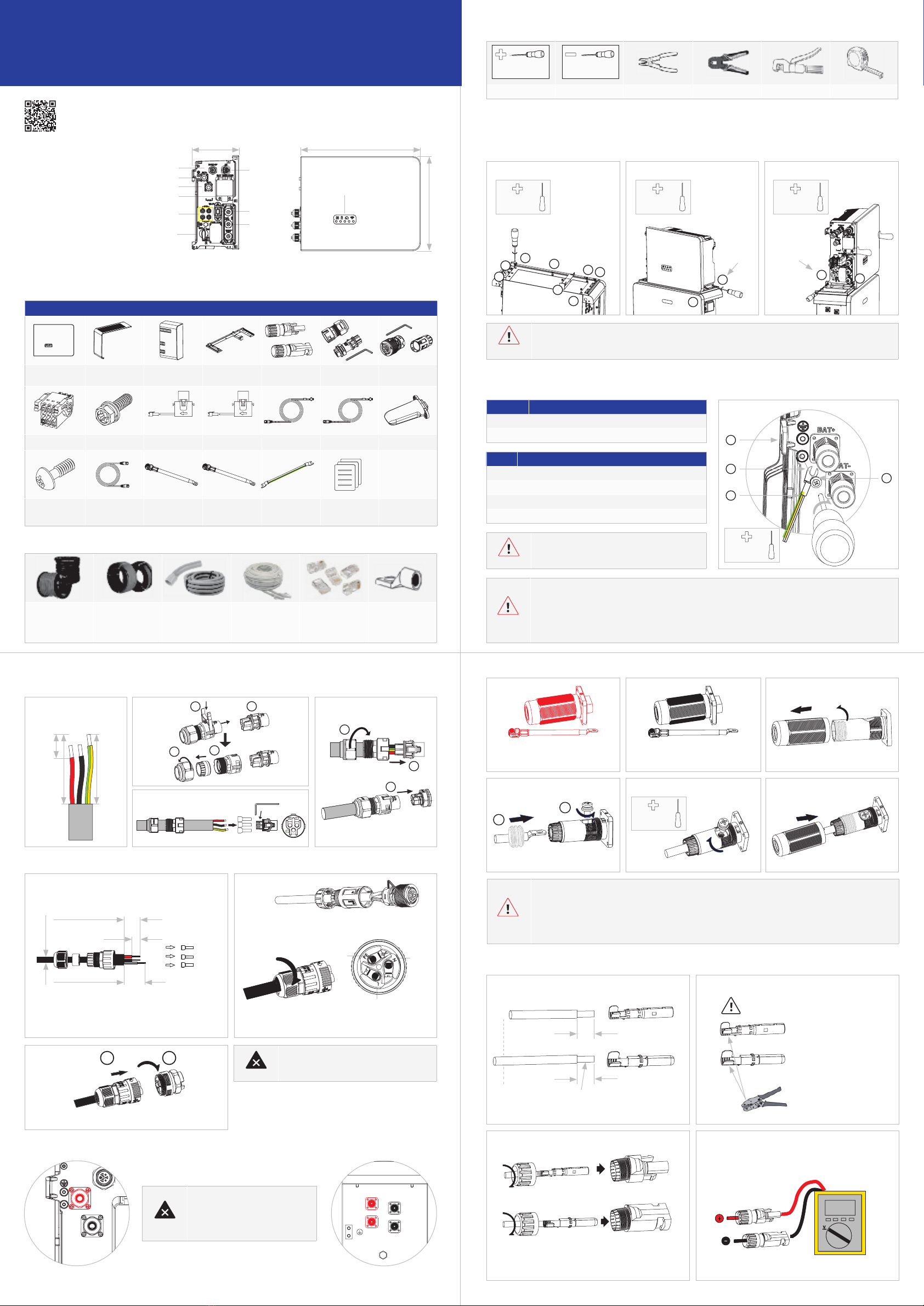
RESERVE-INV-1-
P5-L1-INT (x1)
TOP decoration
plate (x1)
Cable cover
(x1)
Inverter base (x1) PV MC4 connector
pair (X2)
Grid connector (x1) BACK UP
Connector (x1)
AUX Connector (x1) M5*12 Screw (x16) Grid CT (x1) PV CT (x1) Grid CT Cable (x1) PV CT Cable (x1) WiFi Module (x1)
Screw M4*10 (x2) Battery
Communication
Cable (x1)
Battery Positive
Power Cable (x1)
Battery Negative
Power Cable (x1)
Grounding Cable
(x1)
Inverter Quick
Installation Guide
(x1)
Grid-CT PV-CT
Three-core outdoor
copper cable
Grid Cable: 6-8mm
AC Backup Cable:
4-6mm
DC Cable: PV1-F
Conductor cross-
section: 4-6mm
Conduits Ethernet Cables Cat5e,
UTP, UV-resistant for
outdoor use
RJ45 Plugs PE Terminal
Phillips Screwdriver Flat-Head Screwdriver Wire Stripper Network Plug Clamp Crimping Pliers Tape Measure
PH2x150mm 1.2x75mm
PH2x150mm
2.5Nm
PH2x150mm
2.5Nm
PH2x150mm
2.5Nm
PH2x150mm
4.5-5Nm
PH2x150mm
2.5Nm
1
1
2
4
2
3
3
6
8
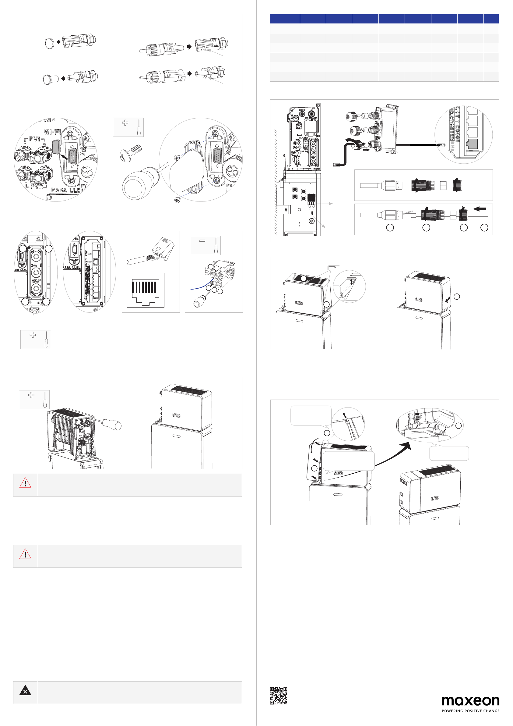
1. Installing the base of the inventer
screw
screw
9
2. Lock right screws 3. Lock left screws
10 11
7
5
412
You must protect each inverter with an individual AC
circuit breaker in order to ensure that the inverter can
disconnected safely.
Bore doing any electrical connection, ensure the PV switch, AC and BAT circuit breaker are switched OFF and
cannot be reactivated.
Please ensure that the connector has been
correctly installed.
1. Switch OFF the battery breaker
which is located on the right
side of the battery
(Black) then the BAT+ wire (Red)
to 40A, otherwise the circuit breaker may trip under normal operation conditions.
release.
short-circuiting of the positive and negative battery pwer cables.
Position
1 Housing
2 M5 terminal lug with protective conductor
3 M5x12 PH2 head screw
4 PE cable
Grid side 32/40/50 A
Backup side 32A
32mm
30mm
14mm
1.
Stripping 14mm
1.
3.
2.
2.
3.
4.
1.
2. 3. 4.
PE
L N
1
1
2
2
4
3
3
Three-core (L, N and PE) outdoor copper cable
Conductor cross-section: 4-6mm²
8mm
PE
L
N
Insert the crimped conductors, L, N and PE into the
corresponding terminals and tighten the screws (torque
1.5±0.1N-m)
Assemble the locking cap, threaded sleeve and swivel nut
together
Plug the connector into the socket and tighten firmly
1 2
Inverter side
1
2
1. Strip off the insulation.
7mm
7mm
4-6mm²
2. Assemble the MC4 cable ends.
3. Assemble the connectors.
Please check if the cables are securely installed by pulling
outwards.
2.6-2.9Nm
Positive
Negative
4. Check the polarities of the PV strings. Check
the open-circuit voltage is less than 580V.
NEED MORE HELP?
for more information.