manuals.online logo
Brands
  1. Home
  2. •
  3. Brands
  4. •
  5. Maxon
  6. •
  7. Automobile Accessories
  8. •
  9. Maxon 297080-01 User manual

Maxon 297080-01 User manual

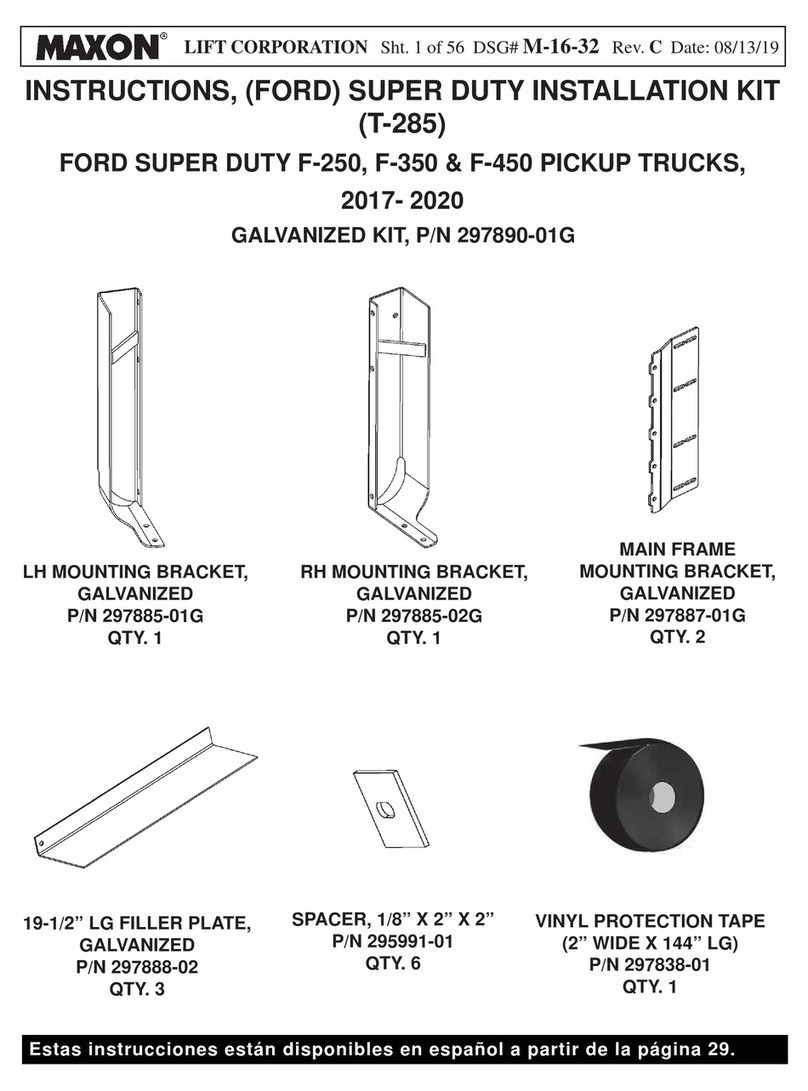
LIFT CORPORATION Sht. 1 of 13 DSG# M-16-04 Rev. ADate: 01/13/17
© MAXON Lift Corp. 2017
INSTRUCTION, BMR STREET-SIDE CONTROL
GRAVITY DOWN CONTROL KIT, P/N 297080-01
POWER DOWN CONTROL KIT, P/N 297080-02
ELECTRICAL CONTROL TEE
P/N 296899-01
QTY. 1
ANGLE, 2” X 2” X 1/8” X 20” LG
P/N 263299
QTY. 1
CAP SCREW
1/4”-20 X 1” LG, GRADE 8
P/N 900004-3
QTY. 4
HEX CAP SCREW
3/8”-16 X 1” LG, GRADE 8
P/N 900014-4
QTY. 2
LOCK NUT, 1/4”-20
P/N 901000
QTY. 8
LOCK NUT, 3/8”-16
P/N 901002
QTY. 2
FLAT WASHER, 3/8”
P/N 902001-2
QTY. 4
WASHER, 1/4”
P/N 903438-01
QTY. 8
PLASTIC ENCLOSURE WITH
GRAVITY DOWN CONTROL (-01 KIT) OR
POWER DOWN CONTROL (-02 KIT)
QTY. 1
ANGLE PLATE
P/N 263264-01
QTY. 1
LIFT CORPORATION Sht. 2 of 13 DSG# M-16-04 Rev. ADate: 01/13/17
© MAXON Lift Corp. 2017
OPERATING INSTRUCTIONS DECAL
P/N 288968-01
QTY. 1
WARNING DECAL
P/N 268416-01
QTY. 1
YELLOW REFLECTIVE TAPE
3” X 1” LG
P/N 090175-14
QTY. 1
LIFT CORPORATION Sht. 3 of 13 DSG# M-16-04 Rev. ADate: 01/13/17
© MAXON Lift Corp. 2017
GROMMET
(P/N 289848-01)
PLASTIC ENCLOSURE
(P/N 297210-02)
ENCLOSURE ASSEMBLY WITH
GRAVITY DOWN CONTROL (-01 KIT)
ENCLOSURE ASSEMBLY WITH
POWER DOWN CONTROL (-02 KIT)
SWITCH ASSEMBLY
(P/N 296150-02)
POWER DOWN
BUTTON
SWITCH MOUNTING
BRACKET (2 PLACES)
(P/N 297374-01)
SOCKET SCREW,
1/4”-20 X 1” LG.
(2 PLACES)
(P/N 900025-1)
GROMMET
(P/N 289848-01)
SWITCH ASSEMBLY
(P/N 296150-01)
PLASTIC ENCLOSURE
(P/N 297210-02)
SOCKET SCREW,
1/4”-20 X 1” LG.
(2 PLACES)
(P/N 900025-1)
SWITCH MOUNTING
BRACKET (2 PLACES)
(P/N 297374-01)
BUTTON SCREW,
1/4”-20 X 3/4” LG.
(4 PLACES)
(P/N 900005-3)
&
FLAT WASHER, 1/4”
(8 PLACES)
(P/N 902000-2)
&
LOCK NUT, 1/4”-20
(4 PLACES)
(P/N 901000)
BUTTON SCREW,
1/4”-20 X 3/4” LG.
(4 PLACES)
(P/N 900005-3)
&
FLAT WASHER, 1/4”
(8 PLACES)
(P/N 902000-2)
&
LOCK NUT, 1/4”-20
(4 PLACES)
(P/N 901000)
LIFT CORPORATION Sht. 4 of 13 DSG# M-16-04 Rev. ADate: 01/13/17
© MAXON Lift Corp. 2017
WIRING HARNESS LOCKING RING CONNECTORS
Before connecting, ensure connectors are clean inside. Ensure there is a thin
coating of dielectric grease on face of receptacle, and there is no dielectric
grease on connector contacts.
CAUTION
Refer to illustrations below for disconnecting,
checking for dielectric grease, and reconnecting
locking ring style connectors.
ALIGN & CONNECT
FIG. 4-5
TURN LOCKING
RING TO UNLOCK
FIG. 4-1
ALIGN TAB &
SLOT
PULL CONNECTOR
TO DISCONNECT
FIG. 4-3
TIGHTEN TO LOCK
FIG. 4-6
PULL LOCKING RING
TO DISENGAGE
FIG. 4-2
DIELECTRIC GREASE
ON RECEPTACLE
FIG. 4-4
LOCKING
RING
THIN COAT OF DIELECTRIC GREASE
ON SHADED AREA
LIFT CORPORATION Sht. 5 of 13 DSG# M-16-04 Rev. ADate: 01/13/17
© MAXON Lift Corp. 2017
LH COLUMN
STREET-SIDE VIEW OF VEHICLE BODY
& LH COLUMN
FIG. 5-1
1. Measure and mark 10” from the LH
column and 2” in from the edge of the
vehicle. Then, position the angle (Kit
item) on crossmembers of vehicle
body (FIG. 5-1).
2 WELDS MIN,
MORE IF POSSIBLE
10”
1/8”
2”
CROSSMEMBER
`
Recommended practices for welding on steel parts are contained in the current
AWS (American Welding Society) D1.1 Structural Welding Code - Steel. Damage
to Liftgate and/or vehicle, and personal injury can result from welds that are done
incorrectly.
WARNING
!
2. Weld the angle to the truck/trailer crossmembers
(FIG. 5-1).
3. Bolt the angle plate (Kit item) to angle
(FIG. 5-2).
HEX CAP SCREW, 3/8”-16
(2 PLACES)
FLAT WASHER, 3/8”
(2 PLACES)
BOLTING ANGLE PLATE TO ANGLE
(LH COLUMN SHOWN)
FIG. 5-2
LOCK NUT, 3/8”-16
(2 PLACES)
ANGLE PLATE
2”X2” ANGLE
2”X2” ANGLE
LIFT CORPORATION Sht. 6 of 13 DSG# M-16-04 Rev. ADate: 01/13/17
© MAXON Lift Corp. 2017
CAUTION
Allow welds to cool before attaching plastic enclosure.
4. Bolt the plastic enclosure (Kit item) to
the angle plate (FIG. 6-1).
LOCK NUT, 1/4”-20
(4 PLACES)
CAP SCREW, 1/4”-20
(4 PLACES)
FLAT WASHER, 1/4”
(8 PLACES)
PLASTIC
ENCLOSURE
BOLTING ENCLOSURE TO ANGLE PLATE
FIG. 6-1
5. Turn OFF the master disconnect switch at the pump
box to disconnect battery power from the hydraulic
pumps. Refer to BMR Operation Manual for detailed
instructions.
ANGLE
PLATE
`
To prevent accidental personal injury and equipment damage, make sure power is
disconnected from Liftgate while installing parts.
WARNING
!
LIFT CORPORATION Sht. 7 of 13 DSG# M-16-04 Rev. ADate: 01/13/17
© MAXON Lift Corp. 2017
7. Disconnect interconnect harness from control switch
cable on the RH column (FIG. 7-1). Then, connect
tee to control switch cable in the RH column and
interconnect harness (FIG. 7-1).
PLASTIC
ENCLOSURE
CONTROL
SWITCH
CABLE
TEE
CONNECTING CABLES TO CONTROL TEE
FIG. 7-1
8. Connect tee to the control switch cable connector
extending from plastic enclosure (FIG. 7-1).
STREETSIDE SWITCH
ASSEMBLY
RH COLUMN
6. Route the tee (Kit item) to the
RH column (FIG. 7-1).
9. Reconnect battery power to the
hydraulic pumps by turning ON the
master disconnect switch at the
pump box. Refer to BMR Operation
Manual for detailed instructions.
LOCKING RING
CONNECTORS
INTERCONNECT
HARNESS
LOCKING RING
CONNECTORS
NOTE: Refer to Sheet 4 for important information
about locking ring electrical connectors.
PUMP ASSEMBLY
(REF)
CONTROL
SWITCH CABLE
LIFT CORPORATION Sht. 8 of 13 DSG# M-16-04 Rev. ADate: 01/13/17
© MAXON Lift Corp. 2017
NOTE: Make sure RUNNERS are raised all
the way up (closest to top of COLUMN)
before doing the following steps.
REFLECTIVE
TAPE
RH COLUMN
ALIGNMENT
ARROW
RUNNER
FIG. 8-1
10. Peel backing from yellow reflective tape (KIt
item) and place it on RH column as shown in
FIG. 8-1. The tape will indicate when the runners
are in correct position for unfolding and folding
the platform.
6”
3”
LIFT CORPORATION Sht. 9 of 13 DSG# M-16-04 Rev. ADate: 01/13/17
© MAXON Lift Corp. 2017
11. Push toggle switch to DOWN position
(FIG. 9-1) to lower platform until yellow runner
arrow is aligned with yellow tape on column
(FIG. 9-2B). Platform will be released from the
locking wedges on the Liftgate column. Next,
use street-side control switches 1and 2to
UNFOLD platform (FIGS. 9-2A and 9-2C). Hold
both toggle switches until platform reaches the
unfolded (horizontal) position and then release
the switches.
UNFOLDING PLATFORM
FIG. 9-2A
NOTE: Use the street-side control switch to
check operation of the Liftgate.
UNFOLD 1
2
STREET-SIDE CONTROL SWITCH
(GRAVITY DOWN SHOWN)
FIG. 9-1
DOWN
STREET-SIDE CONTROL
FIG. 9-2C
FIG. 9-2B
RUNNER
ARROW YELLOW
TAPE
LIFT CORPORATION Sht. 10 of 13 DSG# M-16-04 Rev. ADate: 01/13/17
© MAXON Lift Corp. 2017
12. Attach the OPERATING INSTRUCTIONS
decal (Kit item) to the sleeve on the LH col-
umn (FIG. 10-1).
13. Attach the WARNING decal (Kit item) to the
vehicle body as shown in FIG. 10-1.
ATTACHING DECALS
FIG. 10-1
WARNING
DECAL
OPERATING
INTRUCTIONS
DECAL
LIFT CORPORATION Sht. 11 of 13 DSG# M-16-04 Rev. ADate: 01/13/17
© MAXON Lift Corp. 2017
14. To LOWER platform to the ground,
use street-side control switch as
shown in FIG. 11-1. Release toggle
switch when platform reaches the
ground.
DOWN
LOWERING PLATFORM TO GROUND
USING STREET-SIDE CONTROL SWITCH
FIG. 11-1
15. To RAISE platform, use street-side
control switch as shown in FIG. 11-2.
Release switch when platform reaches
bed height.
RAISING PLATFORM
USING STREET-SIDE CONTROL SWITCH
FIG. 11-2
UP
LIFT CORPORATION Sht. 12 of 13 DSG# M-16-04 Rev. ADate: 01/13/17
© MAXON Lift Corp. 2017
17. Hold both toggle switches 1and 2to
FOLD platform (FIG. 12-2).
FOLDING PLATFORM
USING STREET-SIDE CONTROL SWITCH
FIG. 12-2
FOLD
1
2
16. To stow platform, push toggle switch to
DOWN position (FIG. 12-1A).Lower plat-
form until yellow runner arrow is aligned
with yellow tape on column (FIG. 12-1B).
STOWING PLATFORM USING
STREET-SIDE CONTROL SWITCH
FIG. 12-1A
DOWN
FIG. 12-1B
RUNNER
ARROW YELLOW
TAPE
LIFT CORPORATION Sht. 13 of 13 DSG# M-16-04 Rev. ADate: 01/13/17
© MAXON Lift Corp. 2017
18. Push toggle switch to raise (UP) platform to
upper locking position as follows (FIG. 13-1A).
Raise platform until round wedge on each
opener arm is behind the upper locking wedge
on each column (FIG. 13-1B).
ROUND
WEDGE
UPPER
LOCKING
WEDGE
OPENER
ARM
PLATFORM STOWED IN
UPPER LOCKED POSITION
FIG. 13-1A
UPPER LOCKING
WEDGE ENGAGED
FIG. 13-1B
`WARNING
!
Upper locking wedges must be engaged before moving vehicle.
UP

This manual suits for next models

1

Other Maxon Automobile Accessories manuals

Maxon DMD-22 Operating instructions

Maxon

Maxon DMD-22 Operating instructions

Maxon 297890-01G User manual

Maxon

Maxon 297890-01G User manual

Maxon Railift Series User manual

Maxon

Maxon Railift Series User manual

Maxon TUK-A-WAY Series User manual

Maxon

Maxon TUK-A-WAY Series User manual

Maxon GPTWR-25 Operating and maintenance instructions

Maxon

Maxon GPTWR-25 Operating and maintenance instructions

Maxon 49-SX User manual

Maxon

Maxon 49-SX User manual

Maxon TE-25 User manual

Maxon

Maxon TE-25 User manual

Maxon GPC X1-LDF User manual

Maxon

Maxon GPC X1-LDF User manual

Maxon T-181 User manual

Maxon

Maxon T-181 User manual

Maxon GPTLR-25 User manual

Maxon

Maxon GPTLR-25 User manual

Maxon DMD-22 User manual

Maxon

Maxon DMD-22 User manual

Maxon 49-HX User manual

Maxon

Maxon 49-HX User manual

Maxon DMD series User manual

Maxon

Maxon DMD series User manual

Popular Automobile Accessories manuals by other brands

Hypertech POWER PROGRAMMER III installation instructions

Hypertech

Hypertech POWER PROGRAMMER III installation instructions

Promate CarShade user guide

Promate

Promate CarShade user guide

Brica Seat Guardian 60007 user manual

Brica

Brica Seat Guardian 60007 user manual

Pleasure-Way 2020 TOFINO owner's manual

Pleasure-Way

Pleasure-Way 2020 TOFINO owner's manual

Rockford Fosgate DSR1 user manual

Rockford Fosgate

Rockford Fosgate DSR1 user manual

HaWeKo VWM285 installation manual

HaWeKo

HaWeKo VWM285 installation manual

Nav TV AUDI-09 INT MMi manual

Nav TV

Nav TV AUDI-09 INT MMi manual

Axxess Automobile Accessories installation instructions

Axxess

Axxess Automobile Accessories installation instructions

Discount Car Stereo AUX-GM2 Quick start installation guide

Discount Car Stereo

Discount Car Stereo AUX-GM2 Quick start installation guide

MovaNext Bike adapter 3 Assembly instructions

MovaNext

MovaNext Bike adapter 3 Assembly instructions

Cruz Evo Rack Pro P23-126 Assembly instructions

Cruz

Cruz Evo Rack Pro P23-126 Assembly instructions

Nokia CK-100 Quick installation guide

Nokia

Nokia CK-100 Quick installation guide

Yakima KingPin 2 manual

Yakima

Yakima KingPin 2 manual

Parrot MKi9200 RU quick start guide

Parrot

Parrot MKi9200 RU quick start guide

Century 3212 owner's manual

Century

Century 3212 owner's manual

Mercedes-Benz 171.456 2005 installation instructions

Mercedes-Benz

Mercedes-Benz 171.456 2005 installation instructions

Connects2 CT23VW21 installation manual

Connects2

Connects2 CT23VW21 installation manual

Sune Technology QHLI-LVTX-5CH-ECLIPSE installation manual

Sune Technology

Sune Technology QHLI-LVTX-5CH-ECLIPSE installation manual

manuals.online logo
manuals.online logoBrands
  • About & Mission
  • Contact us
  • Privacy Policy
  • Terms and Conditions

Copyright 2025 Manuals.Online. All Rights Reserved.