Maxon T-181 User manual

LIFT CORPORATION Sht. 1 of 56 DSG# M-19-12 Rev. -Date: 01/06/20
INSTRUCTIONS, CHEVY & GMC INSTALLATION KIT
(T-181)
GALVANIZED KIT, P/N 210670-01G
MAIN FRAME
MOUNTING BRACKET,
GALVANIZED
P/N 210664-01G
QTY. 2
PLATE BRACKET,
3.75” X 2.5”,
GALVANIZED
P/N 289545-01G
QTY. 2
MOUNTING BRACKET,
GALVANIZED, LH
P/N 210668-01G
QTY. 1
MOUNTING BRACKET,
GALVANIZED, RH
P/N 210668-02G
QTY. 1
CHEVY & GMC 2500/3500 PICKUP TRUCKS, 2020
Estas instrucciones están disponibles en español a partir de la última pgina.
Estas instrucciones están disponibles en español a partir de la página
29.
FILLER STRIP,
GALVANIZED
P/N 299942-11
QTY. 3

LIFT CORPORATION Sht. 2 of 56 DSG# M-19-12 Rev. -Date: 01/06/20
LOCK WASHER, 3/8”
P/N 902011-4
QTY. 20
FLAT WASHER, 3/8”
P/N 902001-2
QTY. 6
FLAT WASHER,
1-3/8” OD, 1/2”
P/N 902014
QTY. 4
HEX CAP SCREW
1/2”-13 X 1-1/4” LG, GR5
P/N 900781-02
QTY. 6
BOLT KIT P/N, 289488-01
LOCK WASHER, 1/2”
P/N 902011-6
QTY. 6
PAN HEAD SCREW
#10-24 X 3/4” LG.
P/N 900753-07
QTY. 8
HEX NUT, 3/8”-16
P/N 903161-05
QTY. 20
BUTTONHEAD SCREW
3/8”-16 X 1” LG.
P/N 900064-05
QTY. 8
HEX CAP SCREW
3/8”-16 X 1” LG, GR5
P/N 900778-02
QTY. 12
LOCK NUT, 1/2”-13
P/N 040066
QTY. 4

LIFT CORPORATION Sht. 3 of 56 DSG# M-19-12 Rev. -Date: 01/06/20
GALVANIZED TIRE RELOCATOR KIT, P/N 289634-01G
TAIL LIGHT CLIP KIT, P/N 289632-01
LIGHT CLIP
P/N 289631-01
QTY. 2
HEX FLANGE BOLT,
M8 X 12 MM LG.
P/N 901610-01
QTY. 2
TIRE RELOCATOR
(BRACKET),
GALVANIZED
P/N 289633-01G
QTY. 1
LOCK NUT, 1/4-20”
P/N 040366
QTY. 2
PAN HEAD SCREW,
1/4-20 X 3/4” LG
P/N 900002-1
QTY. 2
T-181 BOLT BAG KIT, P/N 299946-02
SLOTTED BACKER
PLATE
P/N 210203-01
QTY. 8
FLAT WASHER, 3/8”
P/N 902011-4
QTY. 8
HEX CAP SCREW
3/8”-16 X 1” LG, GR5
P/N 900778-02
QTY. 8
HEX NUT, 3/8”-16
P/N 903161-05
QTY. 8

LIFT CORPORATION Sht. 4 of 56 DSG# M-19-12 Rev. -Date: 01/06/20
NOTE: C2 Liftgates are shipped with the following parts kits for installing the Liftgate.
The parts are stored in the main frame housing.
C2 LIFTGATE SMALL PARTS & MANUAL KIT
P/N 289484-01
PADLOCK (2 KEYS)
P/N 908221-01
QTY. 1
LUG, 4GA
COPPER, 3/8”
P/N 907278-01
QTY. 4
LICENSE PLATE
LIGHT
P/N 907210-01
QTY. 1
BUTT CONNECTOR,
14-16 AWG
P/N 030491
QTY. 2
CIRCUIT BREAKER,
150 AMP
P/N 907207-02
QTY. 1
SELF-TAPPING SCREW,
1/4”-20 X 5/8” LG.
P/N 900705-02
QTY. 2
GROMMET NUT, 1/4”
P/N 901015-03
QTY. 2
NYLON PLUG, 1/2”
P/N 908081-01
QTY. 5
PAN HEAD SCREW,
#10-24 X 3/4” LG.
P/N 900007-6
QTY. 2
NUT, #10-24
P/N 903163-02
QTY. 2
DROP-AWAY PIN
P/N 289483-01
QTY. 1
LOCK NUT, 3/8”-16
P/N 901016-4
QTY. 1
C2
OPERATION
MANUAL
M-14-36
LICENSE
PLATE LIGHT
INSTALLATION
M-14-35
PLASTIC TIE
P/N 205780
QTY. 8
LOCK NUT, #10-24
P/N 901003
QTY. 4
PAN HEAD SCREW, #10-24, 1/2” LG.
P/N 900753-05
QTY. 4
BREATHER PLUG, 3/8” NPT
P/N 295049
QTY. 1

LIFT CORPORATION Sht. 5 of 56 DSG# M-19-12 Rev. -Date: 01/06/20
C2 LIFTGATE SMALL PARTS & MANUAL KIT (Continued)
P/N 289484-01
CAMERA MOUNTING PLATE (GMC)
P/N 299602-01
QTY. 1
CAMERA MOUNTING PLATE (TOYOTA)
P/N 299604-01
QTY. 1
MAXON 24/7 SUPPORT DECAL
P/N 298634-01
QTY. 1
MOUNTING ANGLE
P/N 289543-02
QTY. 2
LOWER MOUNTING ANGLE
BOLT BAG KIT (13180) P/N 297891-01
HEX CAP SCREW
12 X 3/4” LG
P/N 900045-1
QTY. 12

LIFT CORPORATION Sht. 6 of 56 DSG# M-19-12 Rev. -Date: 01/06/20
The C2 is a body-mounted liftgate that
put forces on the side walls of truck bod-
ies (FIG. 6-1). For correct installation,
truck bodies must be strong enough to
withstand the tension, compression and
shear forces shown in FIG. 6-1.
X= Tension on each sidewall
Y= Compression on each sidewall
Z= Shear on each sidewall
Consult vehicle body manufacturer for vehicle body strength data. Make sure the
forces created by the Liftgate are within the limits prescribed by the vehicle body
manufacturer.
WARNING
BODY STRENGTH
NOTE: Maximum operating bed height for C2 mounted on pickup body is 42” (Unload-
ed). Minimum bed height is 28” (Loaded).
!
NOTE: Installer is responsible for ensuring vehicle meets Federal, State, and Local
standards and regulations.
C2 LIFTGATE SHOWN ON TRUCK BODY
FIG. 6-1
X= 2600 LB
BED HEIGHT
Z= 2000 LB
Y= 2600 LB

LIFT CORPORATION Sht. 7 of 56 DSG# M-19-12 Rev. -Date: 01/06/20
PREPARE LIFTGATE
1. Remove mounting kits shipped with Liftgate. Refer to
kits on Sheets 1 through 6. Verify mounting brackets
are the correct brackets for this installation.
LH COLUMN
RH COLUMN
REMOVING SHIPPING ANGLES
FIG. 7-1
ANGLE
(2 PLACES)
3/8”-16 BOLT,
3/8” LOCK WASHER,
3/8”-16 NUT
(4 PLACES)
2. Support Liftgate on ship-
ping pallet with forklift or
pallet jack. Unbolt and
remove cover from the
main frame housing. Then,
unbolt shipping angle from
each column on the Liftgate
(FIG. 7-1). Save shipping
angles to use for lower
mounting brackets.
`
Liftgate will not stand upright without the shipping angles. Before removing the
angles, make sure Liftgate is supported with forklift or pallet jack. Injury & prop-
erty damage could result if Liftgate falls over.
CAUTION
!
SPACER
(2 PLACES)
5/16” HEX NUT,
5/16” FLAT WASHERS
(3 PLACES)
REMOVING BRACKET PLATES
(PLATFORM NOT SHOWN)
FIG. 7-2
3. Unbolt bracket plates
from bottom of main
frame housing (FIG. 7-2).
Save the plates to use for
lower mounting brackets.
COVER
BRACKET PLATE
(2 PLACES)
3/8” FLAT WASHER
(2 PLACES)
3/8”-16 BOLT
(2 PLACES)

LIFT CORPORATION Sht. 8 of 56 DSG# M-19-12 Rev. -Date: 01/06/20
REMOVE KNOCKOUTS
KNOCKOUTS
MAIN FRAME
REMOVING KNOCKOUTS FROM
MAIN FRAME HOUSING
FIG. 8-1
PREPARE LIFTGATE - Continued
4. Verify which knockouts to remove from the
bottom of main frame housing (FIG. 8-1).
Then, remove the knockouts as needed.

LIFT CORPORATION Sht. 9 of 56 DSG# M-19-12 Rev. -Date: 01/06/20
MAIN FRAME
MOUNTING BRACKET
(2 PLACES)
BOLTING ON MAIN FRAME BRACKETS
Bolt the main frame mounting
brackets (Kit items) to column
flats using eight 3/8” x 1” buttton-
head bolts (Kit items), eight 3/8”
lock washers (Kit items), and
eight 3/8” hex nuts (Kit items)
(FIGS. 9-1 and 9-2).
C2 LIFTGATE SHOWN WITH BOLT-ON
MAIN FRAME BRACKETS
FIG. 9-1
COLUMN
(2 PLACES)
COLUMN FLAT
(2 PLACES)
3/8” LOCK WASHER
(8 PLACES)
3/8” NUT
(8 PLACES)
3/8” X 1”
BUTTONHEAD BOLT
(8 PLACES)
MAIN FRAME
MOUNTING BRACKET
(2 PLACES)
C2 LIFTGATE - BOLTING MAIN FRAME MOUNTING
BRACKETS TO COLUMNS (TOP VIEW)
FIG. 9-2
COLUMN FLAT
(2 PLACES)
RH COLUMN (REF)
57-5/8”
NOTE: Before installing main frame brackets, ensure mounting bracket is posi-
tioned so the middle slot is closest to the top of the bracket.
MIDDLE SLOT
TOP

LIFT CORPORATION Sht. 10 of 56 DSG# M-19-12 Rev. -Date: 01/06/20
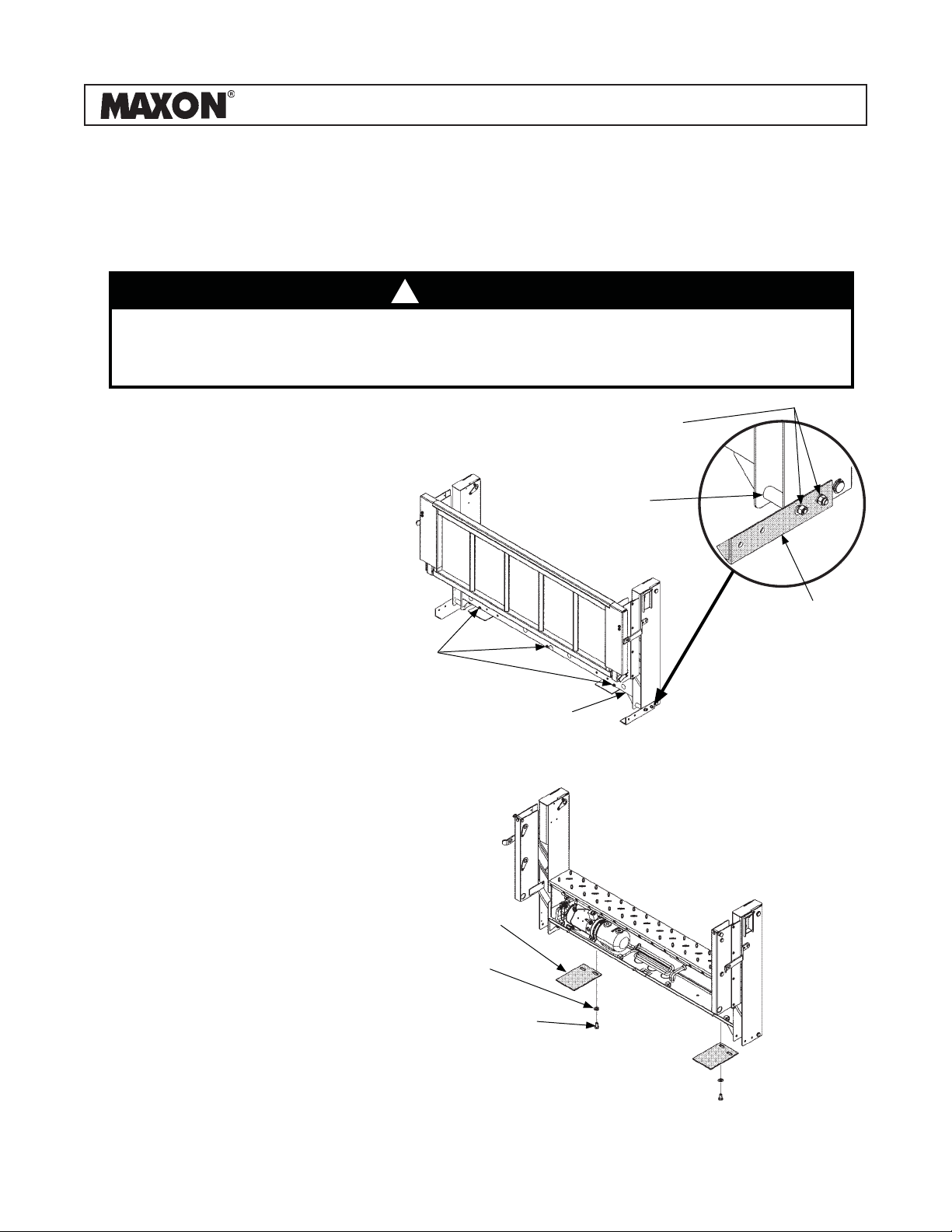
PREPARING PICKUP TRUCK
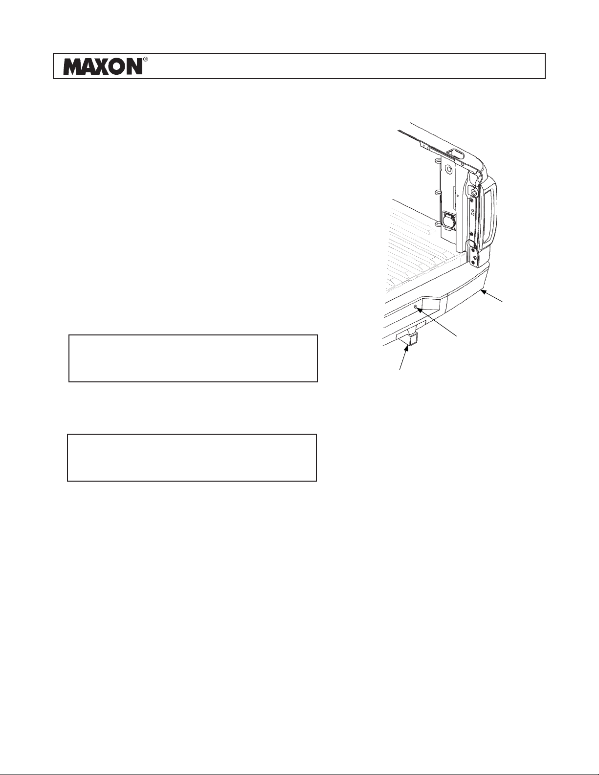
1. Use truck igniton key to unlock the spare
tire access plug (FIG. 10-1). Remove the
plug.
2. Remove spare tire from truck (FIG. 10-1).
Refer to instructions in the owner’s manual
and use the tools provided with truck.
4. Support rear bumper and trailer hitch
(FIG. 10-1) before unbolting the bumper
and hitch.
5. Unbolt and remove trailer hitch (FIG. 10-1).
6. Disconnect the wiring clips from rear bumper
(FIG. 10-1).
7. Unbolt and remove rear bumper (FIG. 10-1).
3. Unbolt the tailgate and supports (FIG. 10-1).
8. If an aftermarket hitch is to be installed, install new
hitch now.
NOTE: If truck is equipped with dual rear
wheels, side marker lamps may have
to be disconnected and rewired.
NOTE: When Liftgate is installed on the truck
tailgate, trailer hitch, and rear bumper
cannot be reinstalled.
REMOVING TAILGATE, REAR
BUMPER & TRAILER HITCH
FIG. 10-1
REAR
BUMPER
SPARE TIRE
ACCESS PLUG
TRAILER
HITCH

LIFT CORPORATION Sht. 11 of 56 DSG# M-19-12 Rev. -Date: 01/06/20
CHANGING TAILLIGHT MOUNTING
1. Remove 2 original taillight screws
and RH taillight lens from pickup bed
(FIG. 11-1). Repeat for LH taillight
lens.
INSTALLING TAILLIGHT MOUNTING CLIPS
FIG. 11-1
RH
TAILLIGHT
LENS
NOTE: Change the taillight mounting fasteners before installing Liftgate. The new fas-
teners will allow both taillight lenses to be removed after Liftgate is installed.
2. Ensure all tailgate mounting fasteners
have been removed (FIG. 10-1).
3. Reinstall the LH and RH taillight lenses
(FIG. 11-1) without using the original
fasteners.
4. Insert M8 X 12 flange bolt (Kit item)
through taillight clip (Kit item) for each
taillight lens (FIG. 11-1). Then, fasten
clip to the tailgate cable catch bolt hole
on the RH and LH side of opening in
the pickup bed (FIG. 11-1).
5. Press clip against each taillight lens and
tighten bolt (FIG. 11-1).
TAILLIGHT
SCREW
(REMOVE)
TAILLIGHT
SCREW
(REMOVE)
PRESS CLIP,
TIGHTEN BOLT
M8 X 12
FLANGE
BOLT
TAILLIGHT
CLIP

LIFT CORPORATION Sht. 12 of 56 DSG# M-19-12 Rev. -Date: 01/06/20
BOLTING ON SPARE TIRE RELOCATOR BRACKET
NOTE: The spare tire relocator bracket provides access to the spare tire hoist after the
Liftgate is installed.
1. Position relocator bracket on the
inside lip of the pickup bed as shown
in FIG. 12-1. Ensure the spare tire
access tube extends through the
large hole in the new bracket.
POSITIONING RELOCATOR BRACKET
(FOR PICKUP)
FIG. 12-1
25-7/8”
RELOCATOR
BRACKET
2. Use relocator bracket as a tem-
plate to mark and drill 2 holes, for
1/4”-20 screws, on the pickup bed
(FIG. 12-1).
HOLE FOR
1/4”-20 SCREW
& LOCK NUT
(2 PLACES)
CAUTION
Before drilling holes in the pickup
bed, ensure there are no obstruc-
tions to drill bit or items behind
sheet metal that could be damaged.
3. Screw the relocator bracket to
pickup bed (FIG. 12-1) with two
1/4”-20 screws and lock nuts (Kit
items).
4. Before installing Liftgate, ensure
plastic plug is removed from spare
tire access hole on rear of the
liftgate.
6-1/16”

LIFT CORPORATION Sht. 13 of 56 DSG# M-19-12 Rev. -Date: 01/06/20
FILLER STRIPS
MAIN FRAME
INSTALLING FILLER STRIP
1. Position the included filler strips (3)
centered along the edge of the main
frame on the Liftgate (FIG. 13-1). Ar-
range the filler strips end to end, with
screw holes horizontal as shown.
NOTE: 3-piece filler strip must be installed prior to mounting Liftgate onto the truck.
2. Ensure the filler strips are properly
aligned and check for any obstruc-
tions along the interior of the main
frame, such as hoses or wiring.
3. Fasten the filler strips to the main
frame of the Liftgate using the
included 12 x 3/4” hex cap screws
(Kit items).
ATTACHING FILLER STRIPS TO
MAIN FRAME
FIG. 13-1
HEX CAP
SCREWS
(12 PLACES)
NOTE: Do not screw into the
Liftgate columns. Ensure
each filler strip is secure
with 4 screws each.

LIFT CORPORATION Sht. 14 of 56 DSG# M-19-12 Rev. -Date: 01/06/20
INSTALLING LIFTGATE
1. Position the LH and RH mounting brack-
ets (Kit items) over the cargo hooks in the
pickup bed (FIG. 14-1).
NOTE: Ensure the Liftgate is in the correct position on pickup bed before marking and
drilling holes.
2. Position liftgate in the rear opening of
the pickup bed (FIG. 14-2).
• Liftgate centered on rear opening in
pickup bed
• Columns vertical
• Spare tire access hole aligned with
spare tire tube on truck
• Top of main frame flush with floor of
pickup bed
3. Loosely fasten Liftgate to the RH mount-
ing bracket positioned over the cargo
hooks in the pickup bed using all 3 of the
main frame mounting bracket’s mounting
holes (FIG. 14-2). Repeat for LH side.
NOTE: Ensure nuts and lock washers
are on the inboard side of the
mounting brackets.
RH MOUNTING
BRACKET
CARGO HOOK
CARGO HOOK
RH MOUNTING
BRACKET
3/8” HEX
CAP SCREW
(3 PLACES)
3/8” LOCK
WASHER
(3 PLACES)
3/8” HEX NUT
(3 PLACES)
RH MAIN FRAME
MOUNTING
BRACKET
POSITIONING RH MOUNTING BRACKET
OVER CARGO HOOKS
FIG. 14-1
FASTENING MAIN FRAME MOUNTING
BRACKET TO RH MOUNTING BRACKET
FIG. 14-2
CARGO LIGHT
(REF)
POWER
OUTLET
(REF)

LIFT CORPORATION Sht. 15 of 56 DSG# M-19-12 Rev. -Date: 01/06/20
SLOTTED
BACKER PLATE
(4 PLACES)
NOTE: To fill gaps between mounting bracket and floor, use 3/8” flat washers
with each bolt.
4. Let Liftgate hang from the corner posts.
Allow some weight to rest on the pickup
bed in order to hang properly.
CAUTION
Before drilling holes in the pickup
bed, ensure there are no obstruc-
tions to drill bit or items that could
be damaged.
5. Hold RH mounting bracket against
cargo hooks and floor of the pickup bed
(FIG. 15-1). Then, using the holes in the
bracket as a guide, drill two 7/16” holes
for 3/8” hex cap screws in floor of the
pickup bed (FIG. 15-1). Repeat for LH
mounting bracket.
6. Bolt RH mounting bracket to the pickup
floor as shown in FIG. 15-1. Repeat for
LH mounting bracket.
7. Drill four 7/16” holes for 3/8” hex cap
screws into the side of the pickup bed,
using the bracket holes near the cargo
hooks as guides (FIG. 15-1).
8. Bolt RH mounting bracket to the side of
pickup bed as shown in FIG. 15-1. Repeat
for LH mounting bracket.
9. Adjust Liftgate to ensure it is centered in
the pickup bed opening, level with ground,
and as flush as possible with the rear of the
pickup bed. Then, tighten the bolts to secure
the main frame mounting brackets to the RH
and LH mounting brackets.
3/8” HEX CAP
SCREW
(6 PLACES) BACKER
PLATE
3/8” LOCK WASHER
(2 PLACES)
3/8” HEX NUT
(2 PLACES)
3/8” LOCK
WASHER
(4 PLACES) 3/8” HEX NUT
(4 PLACES)
BOLTING RH MOUNTING BRACKET TO
PICKUP BED
FIG. 15-1
INSTALLING LIFTGATE - Continued
7/16”
DIA.
HOLE
7/16”
DIA.
HOLE
7/16”
DIA.
HOLE

LIFT CORPORATION Sht. 16 of 56 DSG# M-19-12 Rev. -Date: 01/06/20
CHECKING ACCESS TO SPARE TIRE
1. Connect power from a 12 volt truck battery
to the Liftgate power cables extending from
the back of main frame housing.
3. Use the control switch to lower (DN) the
platform to the ground (FIG. 16-1).
USING CONTROL SWITCH
TO LOWER LIFTGATE
FIG. 16-1
CAUTION
Do not use a battery charger for
connecting power to Liftgate power
cables.
2. Refer to operating instructions, in C2
Operation Manual, to unfold platform
and activate the Liftgate.
NOTE: With the POWER ON and
LIFTGATE ACTIVATED lights
on, the Liftgate can be raised
or lowered. If the Liftgate is not
used for 90 seconds, the control
will automatically deactivate.

LIFT CORPORATION Sht. 17 of 56 DSG# M-19-12 Rev. -Date: 01/06/20
36-1/16”
FRONT OF LIFTGATE
LH COLUMN
(DRIVER SIDE)
ACCESS HOLE FOR CHEVY & GM
(REAR OF LIFTGATE MAINFRAME)
4. Remove the correct black
plastic plugs from the cover
and main frame (FIG. 17-1).
5. Insert the spare tire crank
handle through the holes in
the Liftgate main frame.
6. Ensure spare tire can be
accessed using the crank
handle.
REMOVING PLASTIC PLUGS FOR SPARE TIRE
ACCESS, CHEVY & GM PICKUP
FIG. 17-1
4-3/4”
1-1/4” OR 2” DIA. ACCESS
HOLE (FRONT OF LIFTGATE
MAIN FRAME)
CHECKING ACCESS TO SPARE TIRE - Continued

LIFT CORPORATION Sht. 18 of 56 DSG# M-19-12 Rev. -Date: 01/06/20
ROUTING POWER CABLES
1. Remove the small parts and manual kit
from the housing. Refer to Sheet 4 for con-
tents of the kits.
2. Install circuit breaker (FIG. 18-1) inside the en-
gine compartment near truck battery (+) termi-
nal and away from moving parts. Allow enough
room for power cables to be run and for easy
access to circuit breaker.
3. Pull the (+) and (-) power cables through the cord grip
on back of main frame housing. Leave about 2” of
slack, for power cables, inside main frame housing.
4. Route power cables along truck frame to truck
battery (FIG. 18-1). Pull extra cable beyond
the battery terminals. Then, separate positive
(+) cable from negative (-) cable.
5. Cut positive (+) cable to the length required to
reach the AUX terminal of the circuit breaker
(FIG. 18-1), without putting strain on the con-
nection. Install copper lug (Kit item) (FIGS.
18-2 and 18-3). Then, connect to AUX termi-
nal on 150A circuit breaker.
6. Cut remaining positive (+) cable long enough to
reach from the circuit breaker BAT terminal to the
positive (+) battery terminal (FIG. 18-1) without put-
ting strain on the connection. Install copper lugs (Kit
item) on both ends of cable (FIGS. 18-2 and 18-3).
Then, connect cable to BAT terminal on 150A circuit
breaker and positive (+) terminal on battery.
RUNNING POWER CABLES FROM
LIFTGATE TO BATTERY
FIG. 18-1
(+) CABLE
(-) CABLE BATTERY
150A CIRCUIT
BREAKER
MAIN FRAME
HOUSING
PLACING COPPER LUG & HEATSHRINK
TUBING ON POWER CABLE
FIG. 18-2
COPPER LUG
POWER CABLE
(BARE WIRE END)
HEATSHRINK
TUBING
TYPICAL POWER CABLE WITH
COPPER LUG INSTALLED
FIG. 18-3
7. Cut negative (-) cable to length required to reach negative (-) battery terminal
without putting strain on the connection. Install copper lug (Kit item) (FIGS.
18-2 and 18-3). Then, connect cable to negative (-) terminal on battery.

LIFT CORPORATION Sht. 19 of 56 DSG# M-19-12 Rev. -Date: 01/06/20
C2 PICKUP LIFTGATE HYDRAULIC &
ELECTRICAL SYSTEMS DIAGRAM
FIG. 19-1

LIFT CORPORATION Sht. 20 of 56 DSG# M-19-12 Rev. -Date: 01/06/20
INSTALLING CAMERAAND SENSORS (IF EQUIPPED)
1. Note camera mounting bracket and
sensor mounting bracket locations
on mainframe housing (FIG. 20-1).
CAMERA AND SENSOR BRACKET LOCATION
FIG. 20-1
SENSOR MOUNTING
BRACKET
(4 PLACES)
CAMERA MOUNTING
BRACKET
2. Bend camera mounting bracket
approximately 40° for proper
mounting of camera (FIGS. 20-2
& 20-2A).
ADJUST CAMERA BRACKET
FIG. 20-2
FIG. 20-2A
CAMERA MOUNTING
BRACKET
MAINFRAME
HOUSING
40°
Table of contents
Languages:
Other Maxon Automobile Accessories manuals

Maxon
Maxon 49-HX User manual

Maxon
Maxon 297080-01 User manual

Maxon
Maxon 297890-01G User manual

Maxon
Maxon TUK-A-WAY Series User manual

Maxon
Maxon Railift Series User manual

Maxon
Maxon DMD series User manual

Maxon
Maxon GPTLR-25 User manual

Maxon
Maxon TE-25 User manual

Maxon
Maxon DMD-22 User manual

Maxon
Maxon 49-SX User manual
Popular Automobile Accessories manuals by other brands

Metra Electronics
Metra Electronics 99-5800 installation instructions

Rugged Ridge
Rugged Ridge 13579.71 installation instructions

ECS Electronics
ECS Electronics HY-050-DH Fitting instructions electric wiring

Gibson
Gibson 619650 instruction manual

Directed
Directed Directechs DB3 installation guide

Mitsubishi
Mitsubishi FUEL manual