Maxon DMD-22 User manual

To fi nd maintenance & parts information for your Tool Truck DMD Liftgate, go to
www.maxonlift.com. Click the PRODUCTS, RAILIFT & DMD buttons. Open the Main-
tenance Manual in the PRODUCT DOCUMENTATION window. For parts, click on the
PARTS PORTAL, RAILIFT & DMD buttons.
M-21-02
SEPTEMBER 2022
KEEP THIS MANUAL INSIDE OF VEHICLE
Register your liftgate online at http://www.maxonlift.com/support/product-registration.
For a free copy of other manuals that pertain to these liftgate models, please visit our
website at www.maxonlift.com or call Customer Service at (800) 227-4116.
© MAXON Lift Corp. 2022


TABLE OF CONTENTS
WARNINGS ..............................................................................4
LIFTGATE TERMINOLOGY .....................................................5
RECOMMENDED DAILY OPERATION CHECKS ...................6
DECALS .................................................................................8
DECALS & PLATES
................................................................10
FORKLIFT ADVISORY ............................................................11
OPERATION ............................................................................12
UNFOLDING THE PLATFORM ................................................12
LOADING VEHICLE ................................................................16
LOWERING THE PLATFORM .................................................16
POSITIONING LOAD ...............................................................16
RAISING & UNLOADING PLATFORM .....................................18
UNLOADING VEHICLE ...........................................................20
POSITIONING LOAD ...............................................................20
LOWERING & UNLOADING PLATFORM ................................24
STOWING PLATFORM ............................................................26

4
WARNINGS
2. Do not exceed rated load capacity of 2200 lb for Tool Truck DMD-22
Liftgate.
3. Do not allow any part of your body to be placed under, within, or
around any portion of the moving Liftgate or its mechanisms, or in
a position that would trap them between the platform and the fl oor
of truck body (or between platform and the ground) when Liftgate is
operated.
4. Consider the safety and location of bystanders and
location of nearby objects when operating the Liftgate. Stand
to one side of platform while operating the Liftgate. Be certain
that the area the Liftgate will move through during operation
is clear of all obstacles.
5. Comply with all attached instruction decals and warning decals.
11. Above all, USE GOOD COMMON SENSE when operating this
Liftgate.
8. Do not move vehicle unless Liftgate is correctly stowed.
6. Keep decals clean and legible. If decals are illegible or missing,
have them replaced. Get free replacement decals from Maxon.
7. Never drive a forklift on the Liftgate platform.
10. A correctly installed Liftgate will operate smoothly and reasonably
quiet. The only noticeable noise during Liftgate operation is from the
power unit while the platform is being lowered and raised. Listen for
scraping, grating and binding noises and have the problem cor-
rected before continuing to operate the Liftgate.
MAXON Lift Corp. Customer Service
11921 Slauson Ave
Santa Fe Springs, CA 90670
(800) 227-4116
WARNING
!
9. Correctly stow platform when not in use. Extended platforms
could create a hazard for people and vehicles passing by.
1. Incorrect operation of this Liftgate can result in serious personal
injury. Comply with WARNINGS and Liftgate operating instructions
in this manual. Do not allow untrained persons or children to operate
the Liftgate. If you need to replace an Operation Manual, additional
copies are available from:
12. Never use a cell phone while operating the Liftgate.

5
LIFTGATE TERMINOLOGY
RUNNER
PLATFORM
LH COLUMN
MAIN FRAME
HOUSING
COVER
POWER
UNIT
TRANSIT
HOOK
POWER CLOSER
BUTTON
RH COLUMN
HAND HELD
CONTROL
FLIPOVER
CART STOP
GUIDE RAILS
(IF EQUIPPED)
FLIPOVER
PLATFORM
CART STOP

6
RECOMMENDED DAILY OPERATION CHECKS
Make sure batteries are fully charged, battery terminal connections are
clean and tight, and battery box is undamaged.
Visually check that main frame housing cover is bolted on securely and
undamaged. Look for hydraulic fl uid leaks from main frame and columns.
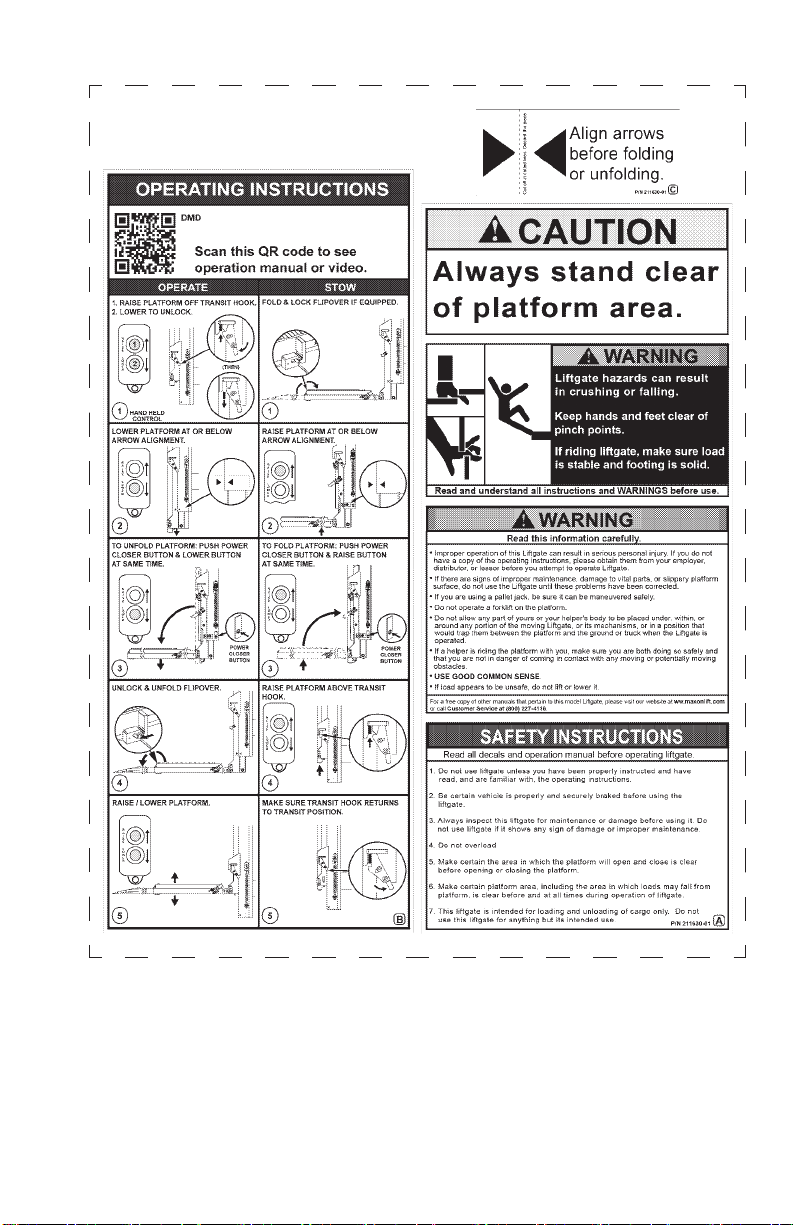
Before operating the Liftgate, the operator should do the following:
Visually check that handheld and power opener controls are in place
and undamaged.
Visually check that all decals are in place (see DECALS page). Make
sure decals are legible, clean, and undamaged.
NOTE: Before you check the Liftgate, park vehicle on fl at ground
and set the parking brake.
NOTE: If any of the following operation checks reveal a need to
service or repair Liftgate, do not operate the Liftgate until a
qualifi ed mechanic services or repairs the Liftgate.
Make sure cab cutoff switch is ON, if equipped.
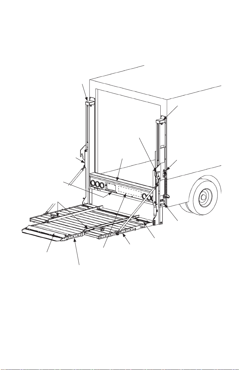
Follow the visible routing of hydraulic hoses from cylinders to main
frame housing . Make sure all hoses are connected at both ends and
there are no cracks, chafi ng, and fl uid leaks.
Use the operation instructions in this manual to unfold the platform.
Check for smooth operation as platform unfolds and as runners lower
the platform to the ground.
Check main frame housing, columns, runners and platform
openers for cracks and bends. Make sure platform chains are undam-
aged and connected securely at both ends. Also, make sure all bolts
and pins are in place and undamaged.
Check platform and fl ipover for cracks, holes, and bends on the load-
carrying surfaces and side plates. Also, make sure carts stops and
guide rails are undamaged and are not missing parts.
Position top surface of platform at vehicle bed level. Check if platform
surface is even with liftgate main housing across the width of the plat-
form. If platform is uneven, press RAISE button on control switch until
platform stops. Hold for 10 seconds more to get platform even.

7
Use the operation instructions in this manual to operate the Liftgate
through one cycle without a load on the platform. Raise the platform
to vehicle bed height. Next, lower the platform to ground level.
When raising and lowering platform, listen for unusual noises and look
for a “jerking” motion or uneven movement at LH and RH sides of the
platform. Uneven movement should not exceed 1”.
If service or repairs are not required (or if completed), stow platform
for transport.
Guide rail(s) release, rotate smoothly, and remain in positions
until intentionally moved.
Carts stops release, open, and close smoothly and
remain so until intentionally opened or stowed.
With platform at bed height, make sure the LH and RH platform chains
feel even in tightness.

8
DECALS
COLUMN ARROW
DECAL “C”
P/N 211630-01
NOTE: Ensure there is no residue, dirt, or corrosion where decals are
attached. If necessary, clean surface before attaching decals.
CAPACITY DECAL
P/N 220388-03
FAMILY OWNED DECAL
P/N 283445-01
RUNNER ARROW
DECAL “C”
P/N 211630-01
WARNING DECAL
P/N 299274-01
DECAL “B”
P/N 211630-01
DECAL “A”
P/N 211630-01

9
DECAL SHEET
P/N 211630-01

10
DECALS & PLATES
NOTE: Preferred decal layout is shown. Decals on the Liftgate
are attached at the factory, except for the 24/7 SUPPORT
decal. The 24/7 SUPPORT decal is placed at customer’s
or installer’s preference.
FIG. 10-1
PARTS QR CODE
DECAL
P/N 299143-01
SERIAL PLATE
(REF)
MAXON 24/7
SUPPORT DECAL
P/N 298634-01

11
Keep forklift OFF of platform.
FORKLIFT ADVISORY
FIG. 11-1
FIG. 11-2
WARNING
!

12
UNFOLDING THE PLATFORM
OPERATION
TRANSIT
HOOK
PLATFORM
FIG. 12-1A
PLATFORM
STOP
CONTROL SWITCH
(UP)
FIG. 12-1B
1. Raise platform stop off transit hook
(FIGS. 12-1 and 12-1A) by pushing the
control switch
UP button (FIGS. 12-1
and 12-1B).
RAISING PLATFORM STOP OFF TRANSIT HOOK
FIG. 12-1
NOTE: Do RECOMMENDED DAILY OPERATION CHECKS at the
beginning of this manual.

13
2. Rotate transit hook away from platform
stop (FIG. 13-1A). Push control switch
DOWN button (FIG. 13-1B) to lower the
platform until platform stop clears transit
hook and arrow decals align on column
and runner (FIGS. 13-1 and 13-1C).
LOWERING PLATFORM TO ALIGN ARROWS
FIG. 13-1
PLATFORM
STOP
PLATFORM
FIG. 13-1A
TRANSIT
HOOK
ARROW
DECALS
FIG. 13-1C
CONTROL SWITCH
(DOWN)
FIG. 13-1B

14
UNFOLDING PLATFORM
FIG. 14-1
PLATFORM
3. Hold power closer button and control switch
DOWN button (FIGS. 14-1A and 14-1B) at
the same time to unfold platform (FIG. 14-1).
UNFOLDING THE PLATFORM - Continued
CONTROL SWITCH
(DOWN)
FIG. 14-1A
POWER CLOSER
BUTTON FIG.
14-1B

15
4. Push latch in direction of arrow to unlock and
unfold fl ipover (FIGS. 15-1 and 15-1A).
UNFOLDING FLIPOVER
FIG. 15-1
FLIPOVER FIG. 15-1A
LATCH

16
A load should never extend past the edges of the platform. Do not
place unstable loads on platform and do not allow load to exceed
lifting capacity of Liftgate. If standing on platform, do not allow
your feet to extend beyond inboard edge of platform.
WARNING
!
LOADING VEHICLE
POSITIONING LOAD
LOWERING THE PLATFORM
Press control switch DOWN button to
lower platform (FIG. 16-1A). Release
DOWN button when platform reaches
the ground (FIG. 16-1).
FIG. 16-1
CONTROL SWITCH
(DOWN)
FIG. 16-1A
1. For roll-off protection, push
latch (FIG. 16-2) in direction
of arrow and rotate the RH
guide rail to the inboard
position (FIG. 16-2). Repeat
for rail on LH side of platform.
ROTATING GUIDE RAIL TO INBOARD POSITION
(RH VIEW OF PLATFORM)
FIG. 16-2
GUIDE RAIL
(INBOARD POSITION)
GUIDE RAIL
(OUTBOARD POSITION)
LATCH

17
3. Place all loads against the
rear cart stop, with heaviest
part toward the truck body
as shown in FIG. 17-2. Move
loads across the ramp
(FIG. 17-2) to the platform,
but never rest or raise loads
on the ramp. If standing on
platform with the load, stand
in the footprint area shown
and comply with the
preceding WARNING.
LOADING PLATFORM AT GROUND LEVEL
FIG. 17-2
RAMP REAR CART
STOP
OPENING REAR CART STOP
FIG. 17-1
2. Using your foot, push the rear
cart stop opener block to the
open position (FIG. 17-1).REAR CART STOP
(OPEN)
OPENER
BLOCK
GUIDE RAIL
(REF)

18
POSITIONING LOAD - Continued
LOADING VEHICLE - Continued
4. To open front cart stop, push latch
in direction shown in FIG. 18-1.
Lift cart stop to open position
(FIG. 18-1).
OPENING FRONT CART STOP
(RH VIEW OF FLIP OVER)
FIG. 18-1
CART STOP
LATCH
RAISING & UNLOADING PLATFORM
A cart stop can trip you when stepping over it. To prevent possible
injury, get on the platform before putting the cart stop in open
position.
CAUTION
!
1. Press control switch UP
button (FIG. 18-2A) to raise
platform from ground level
to bed height (FIG. 18-2).
Release control switch button
when platform reaches bed
height (FIG. 18-2).
MOVING LOAD INTO VEHICLE
FIG. 18-2
CONTROL SWITCH
(UP)
FIG. 18-2A

19
3. Carefully move the load
into vehicle (FIG. 18-2).
CLOSING REAR CART STOP
FIG. 19-1
OPENER
BLOCK
REAR CART
STOP
(CLOSED)
2. Using your foot, push the rear
cart stop opener block to the
closed position (FIG. 19-1).
CLOSING FRONT CART STOPS
(RH VIEW OF FLIPOVER)
FIG. 19-2
CART STOP
4. To close front cart stop, push
latch in direction shown in
FIG. 19-2. Step on cart stop
and push down into locked
position. (FIG. 19-2).
5. If there are more loads
to put in vehicle, repeat
the previous LOADING
VEHICLE steps for each
load. When loading is
fi nished, use STOWING
PLATFORM procedure in
this manual.
LATCH

20
UNLOADING VEHICLE
POSITIONING LOAD
1. Press control switch DOWN button
to lower platform (FIG. 20-1A).
Release DOWN button when
platform reaches the ground
(FIG. 20-1).
LOWERING PLATFORM
FIG. 20-1
2. To open front cart stop, push
latch in direction shown in
FIG. 20-1. Lift cart stop to
open position (FIG. 20-1).
OPENING FRONT CART STOP
(RH VIEW OF FLIP OVER)
FIG. 20-1
CART STOP
LATCH
CONTROL SWITCH
(DOWN)
FIG. 20-1A
Other manuals for DMD-22
2
Table of contents
Other Maxon Automobile Accessories manuals

Maxon
Maxon 49-SX User manual

Maxon
Maxon DMD series User manual

Maxon
Maxon Railift Series User manual

Maxon
Maxon 297080-01 User manual

Maxon
Maxon TE-25 User manual

Maxon
Maxon GPTWR-25 Operating and maintenance instructions

Maxon
Maxon TUK-A-WAY Series User manual

Maxon
Maxon GPTLR-25 User manual

Maxon
Maxon 49-HX User manual

Maxon
Maxon T-181 User manual
Popular Automobile Accessories manuals by other brands

Fiamma
Fiamma CARRY - BIKE Installation and use instruction

EZ Power Steering
EZ Power Steering EZ ELECTRIC POWER STEERING installation manual

aFe Power
aFe Power 77-86318 instruction manual

travall
travall TDG 1496D Fitting instructions

deiwo
deiwo 160089882 Mounting instructions

YATOUR
YATOUR YT-BTM user manual