Installation and Operational Instructions for
EAS®-Compact®Ratchetting Clutch, Type 49_. _ _0._ Size 4
Synchronous Clutch, Type 49_. _ _5._ Size 4 (B.4.14.4.GB)
18/02/2008 GC/TK/SU Chr. Mayr GmbH + Co. KG Tel.: 08341 / 804-241
Eichenstraße 1 Fax: 08341 / 804-422
D-87665 Mauerstetten http://www.mayr.de
Page 9 of 10 Germany eMail: info@mayr.de
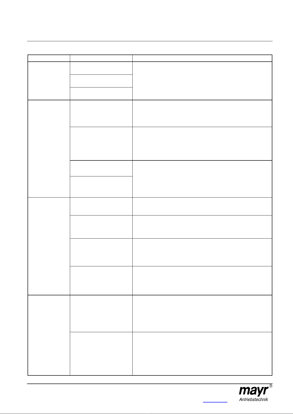
Malfunctions / Breakdowns
Malfunction Possible Causes Solutions
Insufficient clutch securement
Loosened screws
Running noises in
normal operation
Loosened adjusting nut
1) Set the system out of operation
2) Check the clutch securement
3) Check the screw tightening torques
4) Check the torque adjustment and that the adjusting nut sits securely
5) If the cause of the malfunction cannot be found, the clutch must be
inspected at the place of manufacture.
Incorrect alignment
1) Set the system out of operation
2) Find and solve the cause of incorrect alignment (e. g. loose foundation
screws, motor securement breakage, warmth expansion of system
components, changes in the coupling installations dimension "E")
3) Check the coupling for wear
Wear on the elastomeric element,
temporary torque transmission
due to metal contact
1) Set the system out of operation
2) Dismantle the coupling and remove the remains of the elastomeric
element
3) Check the coupling parts and replace them if damaged
4) Insert a new elastomeric element, install coupling parts
5) Check the alignment and correct if necessary
Loose clamping screws and
socket set screws or locking set
screw for axial hub securement
Changes in running
noises and/or
vibrations occurrence
Type 494.-
Loose connection screws
1) Set the system out of operation
2) Check the coupling alignment
3) Tighten the clamping and socket set screws for axial securement of the
hubs as well as the connection screws to the specified torque, or
tighten the locking set screw and paint it with locking solution against
self-loosening
4) Check the coupling for wear
Wear on the elastomeric element,
torque transmission due to
metal contact
1) Set the system out of operation
2) Replace the entire coupling
3) Check the alignment
Cam breakage due to high
impact energy / overload
1) Set the system out of operation
4) Replace the entire coupling
2) Check the alignment
3) Find the cause of overload
Operating parameters do not
match the coupling performance
1) Set the system out of operation
2) Check the operating parameters and select a suitable coupling (please
observe the installation space)
3) Install a new coupling
4) Check the alignment
Cam breakage
Type 494.-
Operational mistakes on the
system unit due to coupling
characteristic data being
exceeded
1) Set the system out of operation
2) Check coupling dimensioning
3) Replace the entire coupling
4) Check the alignment
5) Train operating personnel
Incorrect alignment
1) Set the system out of operation
2) Find and solve the cause of incorrect alignment
(e. g. loose foundation screws, motor securement breakage, warmth
expansion of system components, changes in the coupling installation
dimension "E")
3) Check the coupling for wear
4) Insert a new elastomeric element
Premature wear on
the elastomeric
element
Type 494.- e.g. contact with aggressive
liquids / oils, ozone influences,
excessively high ambient
temperature etc., which lead to
physical changes in the
elastomeric element
1) Set the system out of operation
2) Dismantle the coupling and remove the remains of the elastomeric
element
3) Check the coupling parts and replace them if damaged
4) Insert a new elastomeric element, install coupling components
5) Check the alignment and correct if necessary
6) Make sure that further physical changes to the elastomeric element can
be ruled out.