manuals.online logo
Brands
  1. Home
  2. •
  3. Brands
  4. •
  5. Mayr
  6. •
  7. Industrial Equipment
  8. •
  9. Mayr Smartflex 932.3 3 Series Quick start guide

Mayr Smartflex 932.3 3 Series Quick start guide

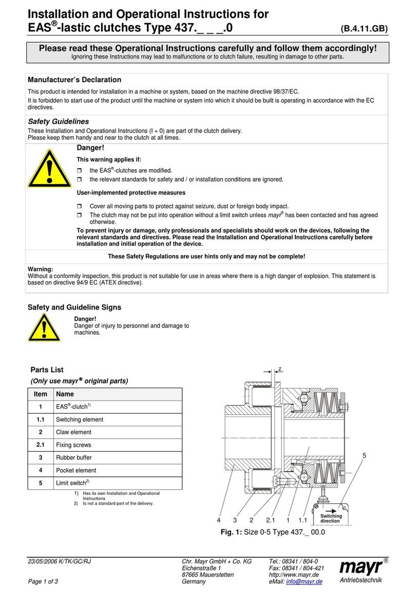
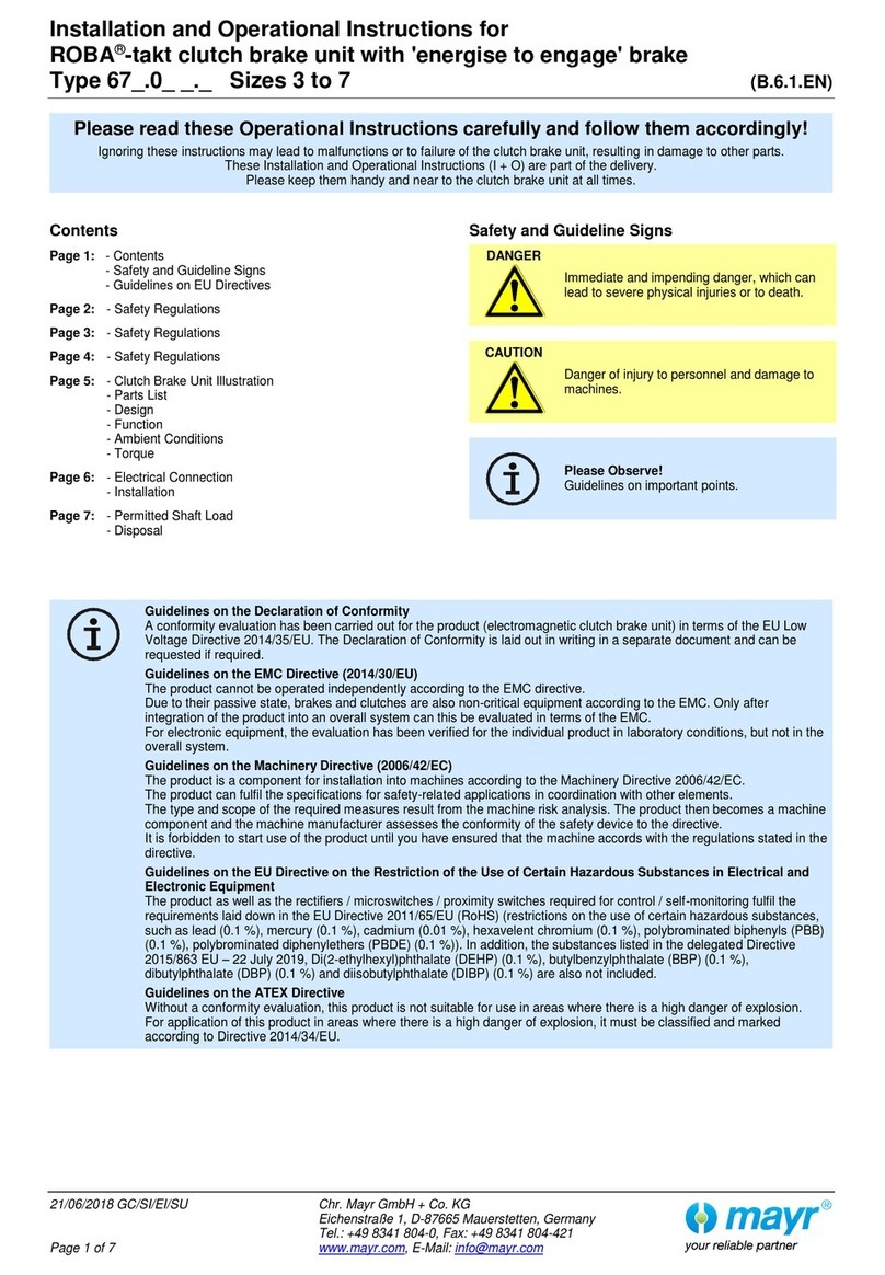
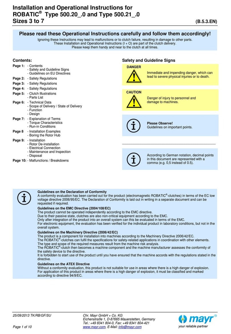
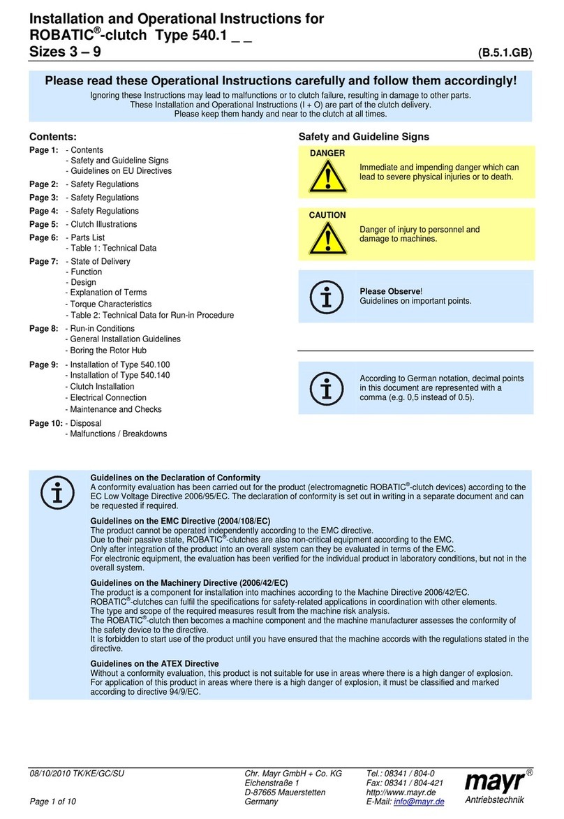
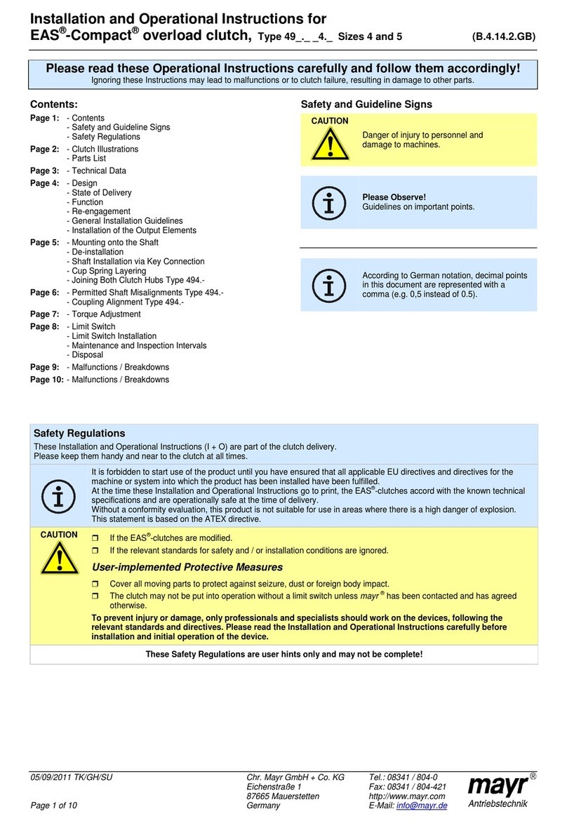
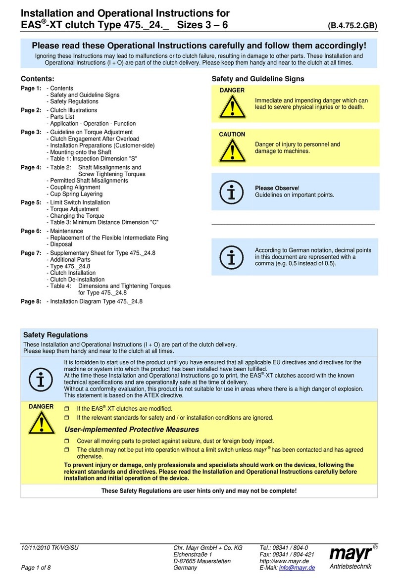
Installation and Operational Instructions for
smartflex®-couplings Types 932.3_3 and 932.433 (B.9.8.GB)
20/08/2008 TK/NV/SU/GC Chr. Mayr GmbH + Co. KG Tel.: 08341 / 804-241
Eichenstraße 1 Fax: 08341 / 804-422
87665 Mauerstetten http://www.mayr.de
Page 1 of 6 Germany eMail: info@mayr.de
Please read the Installation and Operational Instructions carefully
and follow them accordingly.
Ignoring these Instructions may lead to malfunctions or to coupling failure, resulting in damage to other parts.
Contents:
Page 1: - Contents
- Declaration of Conformity
- Safety Regulations
- Safety and Guideline Signs
Page 2: - Coupling Variants
- Parts List
- Table 1: Technical Data
- Table 2: Clamping Connection Bores and
Corresponding Transmittable
Torques TR [Nm]
- Table 3: Preferred Bores
Page 3: - Design
- Function
- State of Delivery
- Installation Guidelines for Shaft Ends
- Adapting to the Shaft Diameter
- Shaft Requirements
- Temperature Resistance
- Installation Position
Page 4: - Coupling Installation
- Important Installation Guidelines
- Installation Types 932.333 and 932.433
- Installation Type 932.343
- Coupling Installation onto Cylindrical Shaft
- Coupling Installation onto Conical Shaft
- Coupling Installation into a Bell-Type Housing
Page 5: - Coupling Dimensioning
- Diagram 1 (Dimensioning Sizes 0 to 2)
- Diagram 2 (Dimensioning Sizes 3 to 5)
- Table 4: Temperature Factors
- Permitted Shaft Misalignments
Page 6: - Maintenance
- Disposal
- Malfunctions / Breakdowns
Please Observe!
According to German notation, decimal
points in this document are represented
with a comma (e.g. 0,5 instead of 0.5).
Declaration of Conformity
A conformity evaluation for the applicable EU directives has been carried out for this product.
The conformity evaluation is set out in writing in a separate document and can be requested if required.
It is forbidden to start use of the product until the machine or system into which it should be built is operating in accordance with all appli-
cable EU directives.
Without a conformity evaluation, this product is not suitable for use in areas where there is a high danger of explosion.
This statement is based on the ATEX directive.
Safety Regulations
These Installation and Operational Instructions (I+O) are part of the coupling delivery.
Please keep them handy and near to the coupling at all times.
Danger!
This warning applies if:
 the shaft couplings are modified.
 the relevant standards for safety and / or installation conditions are ignored.
User-implemented Protective Measures
 Cover moving parts to protect against seizure, dust or foreign body impact.
To prevent injury or damage, only professionals and suitably qualified personnel should work on the devices,
following the relevant standards and directives. Please read the Installation and Operational Instructions
carefully before installing and operating the device.
These Safety Regulations are user hints only and may not be complete!
Safety and Guideline Signs
Danger!
Danger of injury to personnel and damage
to machines.
Please Observe!
Guidelines on important points.
Installation and Operational Instructions for
smartflex®-couplings Types 932.3_3 and 932.433 (B.9.8.GB)
20/08/2008 TK/NV/SU/GC Chr. Mayr GmbH + Co. KG Tel.: 08341 / 804-241
Eichenstraße 1 Fax: 08341 / 804-422
87665 Mauerstetten http://www.mayr.de
Page 2 of 6 Germany eMail: info@mayr.de
Parts List
Only use mayr®original parts
1 Steel bellows
2 Clamping ring
3 Holding spring
4 Cap screw
5 Reducing bushing
6 Reducing bushing with tapered bore
7 Washer
Fig. 1
Table 1: Technical Data
smartflex®Size 0 1 2 3 4 5
Bore reducing bushing (Item 5) from – to [mm]
8 – 19 11 – 25
16 – 36
18 – 50
30 – 62
40 – 85
Tapered bore (Item 6) [mm]
- - - 16 16 - - - - - - - - -
Coupling nominal torque TKN [Nm]
16 40 100 200 400 700
Max. speed nmax. [rpm]
10000 8000 6000 4000 3000 2500
Tightening torque clamping screw (Item 4) [Nm]
10±5% 14±5% 17±5% 41±5% 77±5% 133±5%
Axial displacement ∆Kaon Type 932.3_3 [mm]
±0,4 ±0,6 ±0,8 ±0,8 ±0,8 ±0,6
Axial displacement ∆Kaon Type 932.433 [mm]
- - - ±0,3 ±0,4 ±0,4 ±0,6 ±0,6
Radial misalignment ∆Kron Type 932.3_3 [mm]
0,3 0,4 0,5 0,5 0,5 0,5
Radial misalignment ∆Kron Type 932.433 [mm]
- - - 0,1 0,1 0,1 0,1 0,1
Angular misalignment ∆Kwon Type 932.3_3 [°]
3 3 3 3 1,5 1,0
Angular misalignment ∆Kwon Type 932.433 [°]
- - - 1,5 1,5 1,5 1,2 1,0
Table 2: Clamping Connection Bores and Corresponding Transmittable Torques TR [Nm]
Size Ø
8 Ø
9 Ø
11
Ø
12
Ø
14
Ø
16
Ø
18
Ø
19
Ø
20
Ø
22
Ø
25
Ø
28
Ø
30
Ø
32
Ø
35
Ø
36
Ø
38
Ø
40
Ø
42
Ø
45
Ø
48
Ø
50
Ø
55
Ø
60
Ø
62
Ø
65
Ø
70
Ø
75
Ø
80
Ø
85
0 9,6
11
14
16
16
16
16
16
1 24
26
31
35
39
40
40
40
40
2 60
68
72
75
84
100
100
100
100
100
100
3 120
127
133
147
167
187
200
200
200
200
200
200
200
200
200
200
4 240
256
280
290
305
320
340
360
390
400
400
400
400
5 420
440
475
510
530
580
640
660
690
700
700
700
700
Table 3: Preferred Bores
Size Preferred bores Ø dH7
0 8, 9, 10, 11, 12, 14, 15, 16, 18, 19
1 11, 12, 13, 14, 15, 16, 18, 19, 20, 22, 24, 25
2 16, 17, 18, 19, 20, 22, 24, 25, 26, 28, 30, 32, 35, 36
3 19, 20, 22, 24, 25, 28, 30, 32, 35, 36, 38, 40, 42, 45, 48, 50
4 30, 32, 35, 36, 38, 40, 42, 45, 48, 50, 55, 60, 62
5 40, 42, 45, 48, 50, 55, 60, 62, 65, 70, 75, 80, 85
5
3
4/7
2
1
2
4/7
3
5
6
Installation and Operational Instructions for
smartflex®-couplings Types 932.3_3 and 932.433 (B.9.8.GB)
20/08/2008 TK/NV/SU/GC Chr. Mayr GmbH + Co. KG Tel.: 08341 / 804-241
Eichenstraße 1 Fax: 08341 / 804-422
87665 Mauerstetten http://www.mayr.de
Page 3 of 6 Germany eMail: info@mayr.de
Design
smartflex®-couplings are designed as insertable steel bellows
couplings for the connection of two shafts.
Function
smartflex®-couplings transmit the torque backlash-free and
compensate for radial, axial and angular shaft misalignments.
State of Delivery
 Packed individually in folding boxes or
 Plugged together and secured with cable ties.
 Bores in the reducing bushings (5 and 6) have
H7 tolerances.
Installation Guidelines for Shaft Ends
Fig. 2
Surface quality and run-out accuracy are valid for
conical shafts.
Fig. 3
Adapting to the Shaft Diameter
The reducing bushing (5) can be pressed out of the clamping
ring (2) and replaced using axial pressure (manually or on a
small hand press).
Please Observe!
Due to the offset (see Fig. 4), the reducing
bushing (5) can be pressed out of the
clamping ring only in one direction.
Fig. 4
Shaft Requirements
 Surface quality: Ra = 1,6 µm
 Run-out accuracy: 0,01 mm
 Minimum tensile strength: 500 N/mm2
 Tolerance: h6
For other tolerances, please contact the manufacturer.
Temperature Resistance:
Permanent temperature up to +120 °C
(For higher operating temperatures, please contact the
manufacturer. )
Installation Position: Can be defined by the user.
1,6
Ø d
0,01
M10x1,25
5
5
(28)
40
Ø
1
6
12
Cone 1:10
2
3
5
O
f
f
s
e
t
Installation and Operational Instructions for
smartflex®-couplings Types 932.3_3 and 932.433 (B.9.8.GB)
20/08/2008 TK/NV/SU/GC Chr. Mayr GmbH + Co. KG Tel.: 08341 / 804-241
Eichenstraße 1 Fax: 08341 / 804-422
87665 Mauerstetten http://www.mayr.de
Page 4 of 6 Germany eMail: info@mayr.de
1
2
5
Coupling Installation
Important Installation Guidelines
 Wash off the conserving layer in the bores with paraffin,
white spirit, cleaner solvent or similar.
 The bores and shafts must be grease and oil-free.
 The permitted shaft misalignments (see Table 1) must not
be exceeded.
 Avoid damage to the steel bellows (1) before and during
installation.
 The clamping ring (2) with the holding spring (3) must be
engaged in the reducing bushing (5) or the reducing bushing
with tapered bore (6).
 If a reducing bushing is dismantled or re-installed more than
5 times, the snap ring groove may deform, meaning that its
use is no longer permitted.
 In order to transfer the defined torques in Table 2 on page 2
correctly, the slots in the steel bellows (1), clamping ring (2)
and reducing bushing (5) must be aligned (see Fig. 5).
Coupling Installation Types 932.333 and 932.433
(Fig. 5)
1. Please ensure that the coupling can be easily pushed onto
both shafts.
2. Push the entire coupling over the whole length of the reduc-
ing bushing (5) onto a shaft.
3. Make sure that the steel bellows (1) is pushed between the
clamping ring (2) and the reducing bushing (5) up to its limit,
and that the slots in the steel bellows (1), clamping ring (2)
and reducing bushing (5) are aligned (see Fig. 5).
4. Tighten the cap screw (4). The screw tightening torques (see
Table 1) must be observed.
5. Push the second shaft over the entire length of the reducing
bushing (5) into the coupling.
6. Make sure that the steel bellows (1) is pushed between the
clamping ring (2) and the reducing bushing (5) up to its limit,
and that the slots in the steel bellows (1), clamping ring (2)
and reducing bushing (5) are aligned (see Fig. 5).
7. Tighten the cap screw (4). The screw tightening torque (see
Table 1) must be observed.
Coupling Installation Type 932.343 (Fig. 7)
1. Remove the clamping ring (2) with the protruding reducing
bushing with tapered bore (6) from the coupling.
2. If necessary, insert the key into the conical shaft.
3. Push the reducing bushing with tapered bore (6) onto the
conical shaft.
4. Secure the hub using a nut or a screw with press cover.
5. Push the rest of the coupling with the open steel bellows side
up to its limit between the clamping ring (2) and the reducing
bushing with tapered bore (6).
6. Tighten the cap screw (4). The screw tightening torque (see
Table 1) must be observed.
7. Push the second shaft over the entire length of the reducing
bushing (5) in the coupling.
8. Make sure that the steel bellows (1) is pushed between the
clamping ring (2) and the reducing bushing (5) up to its limit,
and that the slots in the steel bellows (1), clamping ring (2)
and reducing bushing (5) are aligned (see Fig. 5).
9. Tighten the cap screws (4). The screw tightening torques
(see Table 1) must be observed.
Fig. 5
Coupling Installation Types 932.333 / 932.433 onto
Cylindrical Shaft
Fig. 6
Coupling Installation Type 932.343 onto
Conical Shaft
Fig. 7
Coupling Installation into a Bell-Type Housing
Fig. 8
Please Observe!
The slots in the
steel bellows (1),
clamping ring (2)
and reducing
bushing (5) must be
aligned. On the
reducing bushing
with 4 slots, one of
the 4 slots must
align with the slots
in the clamping ring
and steel bellows.
Cap screw (4)
Observe tightening
torque (see table 1)
Steel bellows (1) and
clamping ring (2)
up to limit
Steel bellows (1) and
clamping ring (2)
up to limit
Cap screw (4)
Observe tightening
torque (see table 1)
Cap screw (4)
Observe tightening
torque (see table 1)
Steel bellows (1)
and clamping ring (2)
up to limit
Apply the tools carefully,
the clamping ring (2) is not
secured against turning.
Installation and Operational Instructions for
smartflex®-couplings Types 932.3_3 and 932.433 (B.9.8.GB)
20/08/2008 TK/NV/SU/GC Chr. Mayr GmbH + Co. KG Tel.: 08341 / 804-241
Eichenstraße 1 Fax: 08341 / 804-422
87665 Mauerstetten http://www.mayr.de
Page 5 of 6 Germany eMail: info@mayr.de
Coupling Dimensioning
Please carry out dimensioning using Diagram 1 (Sizes 0 – 2) or
Diagram 2 (Sizes 3 – 5) with "torque M [Nm]" and
"misalignment (%)":
Diagram 1 (Sizes 0 to 2)
Diagram 2 (Sizes 3 to 5)
Determining the coordinates "torque M":
1. Determine the maximum operating torque.
2. Multiply the operating torque with the values from Table 4
(temperature factor) and the service factor applicable for
you, see below (interpolate the interim values).
Service factor fB:
fB = 1,5 with even load.
fB = 2 with uneven load.
fB = 2,5 – 4 with impact load.
For drives in machine tools (servo motors), we recommend the
fB values of 1,5.
Determining the coordinate "misalignment":
1. Determine the individual shaft misalignments in percent,
measured using the permitted shaft misalignments for the
intended coupling size (see Technical Data).
Example for size 2: 0,2 mm axial displacement is 25 % of
the permitted value 0,8 mm.
2. Add up the individual percent values.
The sum total must be smaller than 100 percent
(see also section “Permitted Shaft Misalignments”).
Enter both defined coordinate values into the respective
diagram.
The point of intersection must lie below the characteristic
curve of the intended coupling size.
If the point of intersection lies above the characteristic
curve,
 choose a larger coupling,
 reduce the shaft misalignments or
 contact the manufacturer.
Table 4: Temperature Factors
Temperature [°C] 50 80 100 120
Temperature factor [-] 1 1,1 1,2 1,3
Permitted Shaft Misalignments
The smartflex®-couplings compensate for radial, axial and
angular shaft misalignments (Fig. 9), without losing their
resistance to backlash.
However, the permitted shaft misalignments shown in Table 1
may not simultaneously reach their maximum value. If more than
one kind of misalignment takes place simultaneously, they
influence each other. Therefore, each permitted alignment value
is dependent on another (Fig. 10). The sum total of the actual
misalignments in percent of the maximum value must not exceed
100 %.
Angular misalignment Radial misalignment Axial displacement
Fig. 9
Fig. 10
L - ∆
0
K
a
L + ∆
0
K
a
∆
K
w
∆
K
r
10
20 40 60 80
100
20
30
40
50
60
70
80
90
100
16
0
0
T
o
r
q
u
e
M
[
N
m
]
Misalignment [%]
Size 2
Size 1
Size 0
100
0200 40 60 80
100
400
300
500
600
700
200
Size 5
Size 4
Size 3
T
o
r
q
u
e
M
[
N
m
]
Misalignment [%]
20
30%
25%
75%
0%
50%
20
40%
40
30%
60
60
80
80
100
100
∆
K
[
%
]
R
a
d
i
a
l
m
i
s
a
l
i
g
n
m
e
n
t
r
∆K
misalignment
w
Angular
[%]
∆
K [%] Axial displacement
a
Installation and Operational Instructions for
smartflex®-couplings Types 932.3_3 and 932.433 (B.9.8.GB)
20/08/2008 TK/NV/SU/GC Chr. Mayr GmbH + Co. KG Tel.: 08341 / 804-241
Eichenstraße 1 Fax: 08341 / 804-422
87665 Mauerstetten http://www.mayr.de
Page 6 of 6 Germany eMail: info@mayr.de
Maintenance
smartflex®-couplings are maintenance-free. Special maintenance
work may only be necessary in extreme ambient or operational
conditions.
(In this case, please contact the manufacturer.)
Disposal
All steel components:
Steel scrap (Code No. 160117)
All aluminium components:
Non-ferrous metals (Code No. 160118)
Malfunctions / Breakdowns
Malfunction Possible Causes Solution
Incorrect alignment 1) Set system out of operation
2) Replace the entire coupling
3) Check the alignment
Premature damage on the bellows due
to transportation or installation
1) Set system out of operation
2) Replace the entire coupling
3) Check the alignment
Operating parameters do not match the
coupling performance
1) Set system out of operation
2) Check the operating parameters and select a
suitable coupling (please observe the installation
space)
3) Install a new coupling
4) Check the alignment
Bellows breakage
Bellows is energised in natural frequency, resonance
1) Set system out of operation
2) Re-design the line characteristics
3) Replace the entire coupling
4) Check the alignment
Changes in running
noises and vibration
occurrence
Loosened screws,
resonances, coupling securement is insufficient
1) Set system out of operation
2) Check the screw tightening torques
3) Check the line characteristics
4) Check the coupling parts and replace damaged
coupling parts
Please Observe!
mayr®will take no responsibility or guarantee for replacement parts and accessories which have not been delivered by
mayr®, or for damage resulting from the use of these products.

This manual suits for next models

1

Other Mayr Industrial Equipment manuals

Mayr EAS-Sm User manual

Mayr

Mayr EAS-Sm User manual

Mayr EAS-HT 405 Series Quick start guide

Mayr

Mayr EAS-HT 405 Series Quick start guide

Mayr EAS 400 04.7 Series User manual

Mayr

Mayr EAS 400 04.7 Series User manual

Mayr ROBA-stop 820.61 Series Quick start guide

Mayr

Mayr ROBA-stop 820.61 Series Quick start guide

Mayr EAS-Compact 49 Series Quick start guide

Mayr

Mayr EAS-Compact 49 Series Quick start guide

Mayr ROBATIC 540.1 User manual

Mayr

Mayr ROBATIC 540.1 User manual

Mayr EAS-Compact-R User manual

Mayr

Mayr EAS-Compact-R User manual

Mayr EAS-NC Quick start guide

Mayr

Mayr EAS-NC Quick start guide

Mayr EAS-Compact Quick start guide

Mayr

Mayr EAS-Compact Quick start guide

Mayr ROBA-stop-S Quick start guide

Mayr

Mayr ROBA-stop-S Quick start guide

Mayr EAS-reverse 4100 User manual

Mayr

Mayr EAS-reverse 4100 User manual

Mayr ROBA-stop-S 856 Quick start guide

Mayr

Mayr ROBA-stop-S 856 Quick start guide

Mayr ROBA-ES 94 Series Quick start guide

Mayr

Mayr ROBA-ES 94 Series Quick start guide

Mayr ROBA-servostop 8981.29 01 Quick start guide

Mayr

Mayr ROBA-servostop 8981.29 01 Quick start guide

Mayr ROBA-ES 940 Series Quick start guide

Mayr

Mayr ROBA-ES 940 Series Quick start guide

Mayr ROBA-spot-M 891 Series Quick start guide

Mayr

Mayr ROBA-spot-M 891 Series Quick start guide

Mayr ROBATIC 500.1 Series Quick start guide

Mayr

Mayr ROBATIC 500.1 Series Quick start guide

Mayr EAS-compact 493. 4 .0 Series User manual

Mayr

Mayr EAS-compact 493. 4 .0 Series User manual

Mayr ROBA-servostop 8982.00 01 Quick start guide

Mayr

Mayr ROBA-servostop 8982.00 01 Quick start guide

Mayr EAS-HTL 4190. 5400 Series Quick start guide

Mayr

Mayr EAS-HTL 4190. 5400 Series Quick start guide

Mayr EAS-XT 475.24 Series Quick start guide

Mayr

Mayr EAS-XT 475.24 Series Quick start guide

Mayr ROBA-quick Quick start guide

Mayr

Mayr ROBA-quick Quick start guide

Mayr ROBA 8981.29 01 Series User manual

Mayr

Mayr ROBA 8981.29 01 Series User manual

Mayr ROBA-servostop 8980.00 00 Quick start guide

Mayr

Mayr ROBA-servostop 8980.00 00 Quick start guide

Popular Industrial Equipment manuals by other brands

coval CVGL Series operating instructions

coval

coval CVGL Series operating instructions

Optimum OPTIdrill DH 35G operating manual

Optimum

Optimum OPTIdrill DH 35G operating manual

schmersal AZM201B-ST2-T-1P2PW Instructions for operation

schmersal

schmersal AZM201B-ST2-T-1P2PW Instructions for operation

Tundra TUNENGCRALEV user manual

Tundra

Tundra TUNENGCRALEV user manual

Durapac RG 5 Ton Series instruction manual

Durapac

Durapac RG 5 Ton Series instruction manual

ABB HT609416 Operation manual

ABB

ABB HT609416 Operation manual

Edge Scout 320 manual

Edge

Edge Scout 320 manual

Feurst Turnkey Series Installation and Removal

Feurst

Feurst Turnkey Series Installation and Removal

Jensen EXTREME 870272 manual

Jensen

Jensen EXTREME 870272 manual

SCHUNK KSC-D 80 Installation and operating instruction

SCHUNK

SCHUNK KSC-D 80 Installation and operating instruction

HPM XLP915WEWE instruction manual

HPM

HPM XLP915WEWE instruction manual

Rittal VX25 Blue e+ Assembly and operating instructions

Rittal

Rittal VX25 Blue e+ Assembly and operating instructions

ABB HT565937 Operation manual

ABB

ABB HT565937 Operation manual

ABB Relion 670 series Applications manual

ABB

ABB Relion 670 series Applications manual

Filabot Reclaimer Operation manual

Filabot

Filabot Reclaimer Operation manual

ABB HT610622 Operation manual

ABB

ABB HT610622 Operation manual

ABB HT609308 Operation manual

ABB

ABB HT609308 Operation manual

Graco 24G774 Kit instructions

Graco

Graco 24G774 Kit instructions

manuals.online logo
manuals.online logoBrands
  • About & Mission
  • Contact us
  • Privacy Policy
  • Terms and Conditions

Copyright 2025 Manuals.Online. All Rights Reserved.