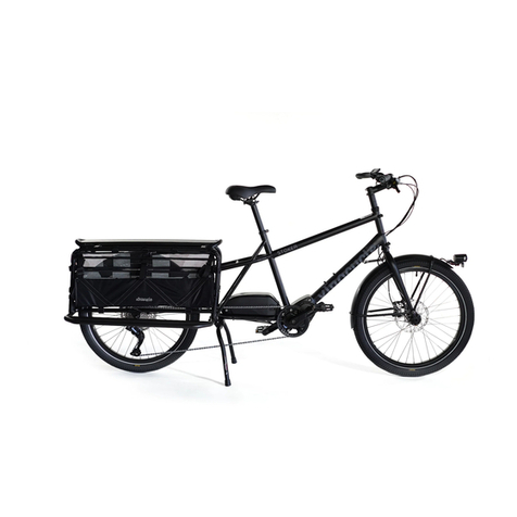
MBM FUNK URBAN 20 User manual

FUNK URBAN 20”
USER MANUAL
FUNK URBAN

FUNK URBAN USER MANUAL
1. FOREWORD 4
1.1 General 4
1.2 Assistance 4
1. 3Graphic form of security warnings 4
2. SECURITY WARNINGS 5
2.1 General safety rules 5
2.2 Responsabilities 5
2.3 Warning for users 6
2.4 Maintenance warnings 6
2.5 Other provisions 7
2.6 Unpacking and tuning 7
2.6.1 Saddle adjustment
7
2.6.2 Handlebar adjustment
8
2.6.3 Pedal mounting
9
3. BICYCLE DESCRIPTION 10
3.1 General description 10
3.2 Data sheet 11
3.3 Brake levers 12
3.4 Speed change 12
3.5 Assistance system management 13
3.5.1 Commands
13
3.5.2 Turning the system on/off
13
3.5.3 Assistance attivation
14
3.5.4 Support levels
14
3.5.5 Single distance reset
15
3.5.6 Walking assistance mode
15
3.5.7 Turning the lights on/off
15
3.5.8 Battery indicators
16
3.5.9 Error codes
16
3.5.10 Problem solving
17
3.6 Battery 18
3.6.1 Battery charge status
18
3.6.2 Battery removal/installation
18
3.6.3 Battery charging
20
3.6.4 Problem solving
20
3.7 Front and rear light 21
3.8 Front suspension 21
INDEX
4. CONDITION OF USE AND INTENDED ENVIRONMENT 22
4.1 Intended use 22
4.2 Environment of use 22
4.3 Improper uses and contraindications 23
5. LIFTING AND TRANSPORT 24
5.1 Lifting 24
5.2 Transport 24
6. COMMISSIONING 25
6.1 Battery charge 25
6.2 Preliminary functional settings 26
6.2.1 Control devices
26
6.2.2 Wheels
26
6.2.3 Braking
26
6.2.4 Frame, handlebar and seat position
27
6.2.5 Brake adjustment
28
6.2.6 Suspension adjustment
28
6.2.7 Headlight operation
29
7. USE OF THE BICYCLE 29
7.1 Driving the bicycle 30
7.2 Braking 30
7.3 Bicycle parking 30
8. MANTEINANCE 31
8.1 General 31
8.2 Daily maintenance and checks 31
8.2.1 Tags and pictograms check
31
8.2.2 Wheel check
31
8.2.3 Brake functional sitting
32
8.3 Weekly maintenance and checks 32
8.3.1 Washing and cleaning
32
8.3.2 Lubrication and chain tension control
32
8.3.3 Frame and bolt control
32
8.4 Monthly maintenance and checks 33
8.4.1 Control of electrical circuits and components
33
8.4.2 Rear derailleur control and adjustment
33

FUNK URBAN USER MANUAL
p.3
9. TECHNICAL ASSISTANCE AND SPARE PARTS 34
10. WAREHOUSE 34
11. DISPOSAL OF COMPONENTS AND MATERIALS 35
12. WARRANTY RULES 36
13. CONFORMITY 37

FUNK URBAN USER MANUAL
p.4
1.FOREWORD
1.1 Generalities
This manual is an integral and essential part of the FUNK URBAN 20” pedal-assisted bicycle. Before commissioning , it
is essential that users read, understand and scrupulously follow the following provisions. The manufacturer is not liable
for damage caused to persons and / or things or to the pedal-assisted bicycle if it is used incorrectly with respect to
the requirements Indicated.
With a view to continuous technological development, the manufacturer reserves the right to modify the components,
including the frame, without notice and without this manual being automatically updated.
1.2 Assistance
For any inconvenience or request for clarification contact the authorized dealer, who has competent and specialized per-
sonnel, as well as specific equipment and original spare parts.
1.3 Graphic form of security warnings
To identify security messages, the following graphical signal symbols will be used in this manual. They have the function
of attracting the attention of the reader / user for the correct and safe use of the assisted bicycle.
Highlights the presence of hazards that cause
residual risks to which the user must pay at-
tention in order to avoid accidents or materi-
al damage.
DANGER
Highlights behavioral rules to be kept in order
to avoid damage to the pedal-assisted bicycle
and / or the onset of dangerous situations.
ATTENTION

FUNK URBAN USER MANUAL
p.5
2. SECURITY WARNINGS
2.1 General safety rules
Even if you are already practical in the use of pedal-assisted bicycles , you must follow the instructions given here, in
addition to the general precautions to be observed during the driving a motor vehicle . In particular:
• Acquire full knowledge of the pedal-assisted bicycle;
• Read the manual carefully to know the operation, the safety devices and all the precautions necessary for the safe use
of the vehicle. All this to allow safe use;
• Carefully maintain the pedal-assisted bicycle in perfect condition;
For any inconvenience or request for clarification contact without hesitation the authorized dealer, who has competent
and specialized personnel, specific equipment and original spare parts.
2.2 Responsabilities
Failure to comply with the operating instructions and safety requirements contained in this manual exempts the man-
ufacturer from any liability.
If the maintenance of the pedal-assisted bicycle is carried out in a manner that does not comply with the instructions
provided, with non-original spare parts or in any case in such a way as to compromise its integrity and modify its charac-
teristics, the manufacturer shall will be relieved of any responsibility inherent in the safety of persons and the defective
operation of the pedal-assisted bicycle.
ATTENTION
USE OF THE PEDAL-ASSISTED BICYCLE
Each user must first have read the instruction manual, in particular the chapter on safety claims.
ATTENTION
RISK ASSOCIATED WITH THE USE OF THE PEDAL-ASSISTED BICYCLE
• Notwithstanding the application of safety devices, for the safe use of the pedal-assisted bicycle , all the requirements re-
lating to the prevention of accidents reported in this manual.
• Always stay focused while driving and DO NOT underestimate the residual risks associated with the use of the assisted
bicycle.

FUNK URBAN USER MANUAL
p.6
For any data not included or not deductible from this manual, it is recommended to consult the authorized dealer directly.
2.3 Warnings for users
1. It can only be used by experienced adults and children;
2. Do not take alcohol or drugs before riding the pedal-assisted bicycle;
3. These models of pedal-assisted bicycles are designed and built to be used outdoors, on roads and private and public
environments;
4. Do not ask the pedal-assisted bicycle for performance higher than that for which it was designed;
5. Never ride the pedal-assisted bicycle with disassembled parts;
6. Avoid uneven surfaces and obstacles;
7. Ride with both hands on the handlebars;
8. Replace worn and/or damaged parts and check that the guards are working properly before use.
2.4 Maintenance warnings
1. Any maintenance must take place with the battery disconnected;
2. During each maintenance phase , operators must be equipped with the necessary accident prevention equipment;
3. The tools used for maintenance must be suitable and of good quality;
4. Do not use gasoline or flammable solvents as detergents, but always resort to non-flammable and non-toxic solvents;
5. Limit as much as possible the use of compressed air for cleaning (max 2 bar) and protect yourself with glasses with
side guards;
6. Never resort to the use of open flames as a means of illumination when carrying out verification or maintenance op-
erations;
7. After any maintenance or adjustment, make sure that no tools or foreign bodies remain between the moving parts of
the pedal-assisted bicycle.
ATTENTION
UNAUTHORIZED CHANGES
If you hear unusual noises or feel something strange, stop the pedal-assisted bicycle immediately. Carry out a check after-
wards and, if necessary, contact the authorized dealer.
ATTENTION
ORIGINAL SPARE PARTS
Use only original spare parts supplied by M.B.M. S.r.l. Unipersonal. Any liability of the Manufacturer for damage or loss of
functionality caused as a result of the use of non-original accessories and parts is excluded.

FIG. 1
FUNK URBAN USER MANUAL
p.7
2.5 Other provisions
The first thing to do when starting use is to check the presence and integrity of the protections and the operation of the
safety devices. If you find any defects, do not use the pedal-assisted bicycle!
2.6 Unpacking and tuning
The pedal-assisted bicycle is delivered fully assembled and working.
2.6.1 Saddle adjustment
The adjustment of the height of the saddle is an essential prerogative for the correct use of the pedal-assisted bicycle.
Incorrect adjustment can generate structural breaks to the frame.
Adjust the height of the saddle by operating the quick release mechanism (Ref. A – Figure 1). Check that the mechanism
is tightened before testing the seat and using the medium. Do not lift the saddle beyond the limit sign placed in the tube
(Ref. B – Figure 1
DANGER
IMPORTANT NOTICE:
For your safety, the reference mark of
the seatpost tube (B) should never be
outside the tube where the seatpost tube
is inserted.
ATTENTION
ASSEMBLY
In the event that you do not have the ap-
propriate instrumentation for adjust-
ment or do not have the capabilities, con-
tact the authorized dealer.
GUARDS
It is strictly forbidden, therefore, to modify or remove the guards, controls, labels and indication plates.
DANGER

FIG. 2
FIG. 3
FUNK URBAN USER MANUAL
p.8
2.6.2 Handlebar adjustment
For a comfortable posture on the bike, which does not cause neck or back pain, we recommend the handlebar column
height adjustment.
Adjust the height of the handlebar column by operating the quick release mechanism (Ref. C – Figure 2). Check that the
mechanism is tight before using the vehicle. Do not lift the handlebar column beyond the height allowed by the mechanism.
To facilitate the transport and storage of the pedal-assisted bicycle, it is possible to unhook and flex the steering column
by means of the centrally placed hinge (Ref. D – Figure 2).
Use the hinge of the handlebar column by lifting the safety
mechanism (Ref. E – Figure 3) and open the hinge.
Check that the release mechanisms are tightened before us-
ing The vehichle.
ATTENTION
ASSEMBLY
In the event that you do not have the appropri-
ate equipment for adjustment or do not have
the capabilities contact the authorized dealer .
ATTENTION
ATTENTION
Do not lift the handlebar column beyond the
maximum height allowed by the mechanism.
Do not use the pedal-assisted bicycle with the
zipper unhooked .

FIG. 4
FUNK URBAN USER MANUAL
p.9
ATTENTION
ASSEMBLY
In the event that you do not have the appropriate
equipment for adjustment or do not have the capa-
bilities, contact the authorized dealer.
2.6.3 Pedal mounting
Right pedal: IT is identified by the letter “R” marked on its
pin. For pedal mounting, screw by turning the pin clockwise.
(Figure 4).
Left pedal: it is identified by the letter “L” marked on its pin.
For pedal mounting, screw by turning the pin counterclock-
wise (Figure 4).
ATTENTION
ASSEMBLY
For a correct tightening of the pedals, it is neces-
sary to use a key of 15

FUNK URBAN USER MANUAL
p.10
3. BICYCLE DESCRIPTION
3.1 General description
The pedal-assisted bicycle is designed and built to be used outdoors, on roads and private or public environments. In
particular, the components and the type of pedal-assisted bicycle allow you to tackle routes with asphalt surfaces or
with similar characteristics without particular roughness.
The pedal-assisted bicycle is equipped with a rechargeable battery and an electric motor, whose intervention takes
place only in conjunction with the pedaling and gradually stops as the speed of the vehicle approaches 25 km / h, and then
stops completely at that speed.
For the management of the assistance system there is a special display located on the left side of the handlebar. On the
right side of the handlebar there is a control system for adjusting the gears.
INCORRECT AND UNINTENDED USE
The bicycle has been designed and manufactured for the specified use; a different use and failure to comply with the technical
parameters set by the manufacturer may constitute a dangerous condition for users.
DANGER

FUNK URBAN USER MANUAL
p.11
3.2 Scheda tecnica
1. HANDLEBAR AND CONTROLS
2. ENGINE
3. SADDLE
4. BATTERY
5. PEDAL
6. FORK
7. FRONT LIGHT
8. REAR LIGHT
9. REAR DERAILLEUR
CODE E500 / E500CR
FRAME HYDROFORMED ALUMINIUM
FORK SUSPENSION WITH ADJUSTMENT
CRANKSET 38 TEETH
REAR DERAILLEUR ACERA
SHIFTERS 8 SPEEDS
BRAKES SHIMANO MT 200 HYDRAULIC
DISKS SHIMANO RT26 ANT: Ø160MM POST:Ø160MM
WHEELS 20*3,0
SADDLE MBM FUNK
PEDAL RIGHT AND LEFT IN NON-SLIP POLYMER MATERIAL
LIGHTS SPANNINGA 40 LUX
ENGINE CENTRAL MOTOR OLI MOVE ONE 60 NM
BATTERY SEMI-INTEGRATEDSPARD YT 30240, 36V, 7AH 252 WH
MAX SERVICE SPEED 25 KM/H
DISPLAY LCD
POWER LEVELS 5
WEIGHT 26 KG

FIG. 5
FUNK URBAN USER MANUAL
p.12
3.3 Brake levers
The brake levers (Ref. F – Figure 5) are placed on the handlebars of the pedal-assisted bicycle, near the knobs (Ref. G – Fig-
ure 5). These systems make it possible to control the calipers of the disc brakes located near the wheel hubs. The right le-
ver controls the rear brake, the left one the front brake; the braking action is proportional to the force applied on the lever.
3.4 Speed change
The pedal-assisted bicycle has an 8-speed gearbox with the sprockets positioned on the rear wheel hub and selecta-
ble by means of the opposing levers located at the base of the right knob. The indicator (Ref. H – Figure 5) presents at the
bottom of the handlebar allows you to view the selected ratio.

FUNK URBAN USER MANUAL
p.13
3.5.2 Turning the system on/off
To activate the system you must first turn on the battery; after that, press and hold the on/off button. (Ref. L - Figure 6).
To turn off the system, press and hold the on/off button (Ref. L - Figure 6).
3.5 Assistance system management
3.5.1 Commands
To manage the assistance system there is a display on the left side of the handlebar. This device allows you to vary the
level of assistance and to view information regarding the path and status of the battery (Figure 6).
FIG. 6
I - Display;
L - On /off button and increase the level of
assistance;
M-Mode button and reduction of the level
of assistance;
N - Lever walking assistance mode.

FUNK URBAN USER MANUAL
p.14
FIG. 7
1 - Battery charge indicator
2 - Speed
3 – Level of assistance
4 – Percentage of battery charge
5- Total Distance Traveled (ODO)/Single Distance (TRIP).
The two values are automatically toggled on the display.
6- Lights
7- Error (see section 3.5.9 for error codes).
3.5.3 Activate support
The engine is activated and deactivated immediately if the pedaling stops. The power of the motor depends on the force
imposed on the pedals according to a multiplicative factor depending on the level of assistance selected.
Press and release the power button (Ref. L - Figure 6) to increase the level of assistance. To decrease the level of assis-
tance press and release the “-” button (Ref. M - Figure 6). The level of assistance can be selected from any screen of the
display.
3.5.4 Assistance level
LEVEL 0 - NOTHING ASSISTANCE
LEVEL 1 - ASSISTANCE 12,5%
Recommended route : plain - long distances
LEVEL 2 - ASSISTANCE 25%
Recommended route : plain/hilly - medium-long distances
LEVEL 3 - ASSISTANCE 50%
Recommended route : hilly /medium climb - medium distances
LEVEL 4 - ASSISTANCE 75%
Recommended route : ascent - medium short distances
LEVEL 5 - ASSISTANCE 100%
Recommended route : challenging climb - short distance
The power of the engine depends on the force imprinted on
the pedals according to a multiplicative factor based on the
selected level of assistance. The assistance drops linearly
until it reaches 25 km/h. Once this speed has been exceeded,
there is automatic deactivation of the assistance.

FUNK URBAN USER MANUAL
p.15
3.5.5 Single distance reset
With the device turned on, press the power button and the “-” button (Ref. L,M - Figure 7.1) at the same time to reset the single
distance (TRIP).
3.5.6 Walking assistance mode
The pedal-assisted bicycle is equipped with the function of walking assistance. This function allows you to move the bike
more easily during manual movement in case you face small climbs.
In flat routes it is useful for starting the ride, up to a speed of 6 km / h.
To activate the above mode, turn on the assistance system using the appropriate button (Ref. L - Figure 7.1).
At this point, set the assistance level to 0 and press the lever (Ref. N - Figure 7.1) to activate the walking assistance mode.
Once the lever is released, the assistance mode automatically turns off
3.5.7 Turning the lights on/off
With the device turned on, press and hold the “-” button (Ref. M - Fig. 7.1) for 3 seconds to turn on the lights of the ped-
al-assisted bicycle; to turn off the lights press and hold the “-” button (Ref. M - Fig. 7.1) for 3 seconds.
The status of switching on and off of the lights of the pedal-assisted bicycle is indicated by the relative icon on the dis-
play (Ref.6 - Fig. 7.1).
FIG. 7.1

FUNK URBAN USER MANUAL
p.16
3.5.9 Error codes
In the event of a malfunction, the display automatically shows a 4-character code corresponding to the fault encoun-
tered. Error codes are displayed on the right side of the display and highlighted by an exclamation mark. To remove the
code to turn the device off and on again.
ERROR CODE DESCRIPTION
0001 PROBLEM COMMUNICATING WITH BATTERY. BATTERY STATUS DATA MAY BE DISPLAYED INACCURATELY. CHECK THAT THE WIRING AND CONTACTS OF THE
BATTERY ARE CONNECTED CORRECTLY AND INTACT.
0101
COMMUNICATION PROBLEMS BETWEEN THE TRANSMISSION UNIT AND THE GRAPHICAL INTERFACE.
CHECK THAT THE WIRING IS INTACT AND CONNECTED CORRECTLY.
0104
SPEED SENSOR NOT DETECTED.
CHECK THAT THE SPEED SENSOR AND MAGNET ARE CORRECTLY ALIGNED.
CHECK THAT THE SENSOR IS INSTALLED AND CONNECTED CORRECTLY.
0105 PROBLEMS WITH THE TORQUE SENSOR SIGNAL. THE TORQUE SENSOR SIGNAL IS FAULTY. THE ENGINE WILL RUN AT REDUCED POWER.
3.5.8 Battery indicators
The state of charge of the battery (Ref.1 - Fig. 7) is indicated on the left side of the display.
When the battery is fully charged, 5 bars appear on the display; the bars gradually decrease as the battery discharges.
When the battery charge is low the last bar flashes to warn that the battery needs to be recharged.
ATTENTION
Depending on the type of failure, the sys-
tem may prevent the engine from start-
ing or running at maximum power.

FUNK URBAN USER MANUAL
p.17
0106 INADEQUATE RESPONSE OF THE TORQUE SENSOR. THE TORQUE SENSOR IS FAULTY.
0801 FAILURE OF THE MOTOR ROTATION SENSOR.
0802 FAILURE OF THE PEDAL ROTATION SENSOR.
0804
CONTROL UNIT TEMPERATURE TOO HIGH.
THE TEMPERATURE SENSOR OF THE CONTROL UNIT DETECTED A TEMPERATURE HIGHER THAN THE PERMISSIBLE LIMIT .
0805 ENGINE TEMPERATURE TOO HIGH. THE ENGINE HAS REACHED A TEMPERATURE HIGHER THAN THE PERMISSIBLE LIMIT.
0806 PERIPHERAL CONNECTOR VOLTAGE ISSUES.
0808 ROTOR LOCKED. THE ENGINE DID NOT START DUE TO A MECHANICAL BLOCKAGE OR A PROBLEM WITH THE TRANSMISSION UNIT CABLE .
0809 THE BATTERY VOLTAGE IS HIGHER THAN THE MAXIMUM ALLOWED.
0810 PROBLEMS WITH THE ELECTRIC CURRENT SENSOR.
0811 THE CONTROL UNIT HAS DETECTED AN EXCESS OF ELECTRIC CURRENT.
1101 COMMUNICATION PROBLEMS BETWEEN THE USER INTERFACE AND THE CONTROL UNIT. CHECK THAT THE CABLE IS INTACT AND CONNECTED CORRECTLY.
1102 ONE OF THE BUTTON PANEL KEYS GOT STUCK IN THE PRESSURE POSITION.
3.5.10 Problem solving
PROBLEM CAUSE/SOLUTION
The display does not turn on Check the connession and central system
How to handle error codes Verify the problem based on the error code description
provided in this manual. ATTENTION-
If the problem persists after these oper-
ations, request support from a service
center.

FUNK URBAN USER MANUAL
p.18
3.6 Battery
The assistance system of the pedal-assisted bicycle, to work, needs
the presence of the power battery.
Specifically, the battery is removable, so you can take it out for
maintenance actions or when you want to store the vehicle.
3.6.1 Battery charge status
You can view the battery charge status directly on the assistance
system management display.
In the event that the battery is disassembled from the vehicle or you
want to see the state of charge without turning on the assistance
system, in the upper part of the battery there is a button (Ref.O – Fig-
ure 8) that allows, through a LED light of different colors (Ref. P –
Figure 8), to display the charge status.
CHARGING STATUS LED:
RED LIGHT 0 – 25%
GREEN LIGHT 25 - 75%
BLUE LIGHT 75 – 100%
FIG. 8
3.6.2 Battery removal/installation
For remove the battery secure who Is the system of assistance who the battery Are Off e proceed What Follows:
1. Insert the battery lock/unlock key into the battery lock at the top right of the frame near the handlebar and turn the
keys clockwise. (Ref. Q – Figure 9)
2. Holding the key rotated, unhook the battery and lift it (Ref. 2 – Figure 9)
1. Take out the battery completely, taking care not to hit the frame.
FIG. 9
1 2 3

FUNK URBAN USER MANUAL
p.19
For install the battery proceed What Follows:
1. This procedure must be performed without the unlock key ; remove the key if inserted;
2. Align the battery above the oblique pipe of the frame by matching the electrical connector (Ref. R – Figure 10);
1. Carefully insert the battery into the frame until you hear the closing click of the lock. At this point the battery is already
self-locked.
FIG. 10
1 2 3

FUNK URBAN USER MANUAL
p.20
3.6.3 Battery charging
The charging of the pedal-assisted battery can be carried out both with the battery fixed to the frame and with the same
extracted and stored in a sheltered environment.
To charge the battery , do the following:
1. Turn off the battery and turn off the assistance system of the pedal-assisted bicycle using the appropriate button on the
display. (Ref. L – Figure 6);
2. Remove the battery in case you want to charge it separately;
3. Lift the rubber stopper at the top right of the battery (Figure 11)
4. Connect the supplied battery charger with the appropriate plug;
5. Connect the battery charger to a power outlet (230 V / 50 Hz) and charge for as long as necessary.
ATTENTION
BATTERY CHARGER
Always connect the plug to the bat-
tery first and then the battery charg-
er to the power outlet.
FIG. 11
3.6.4 Problem solving
ATTENTION
TROUBLESHOOTING
In case the assistance system does not acti-
vate even if the battery is charged, contact
your authorized dealer.
PROBLEM CAUSE/SOLUTION
The system does not turn on Check that the battery is charged.
PROBLEM CAUSE/SOLUTION
Support does not activate Check that the battery charge level is
sufficient.
Table of contents
Other MBM Bicycle manuals