Page 4 1330SE - Service & Parts Manual
November 2021
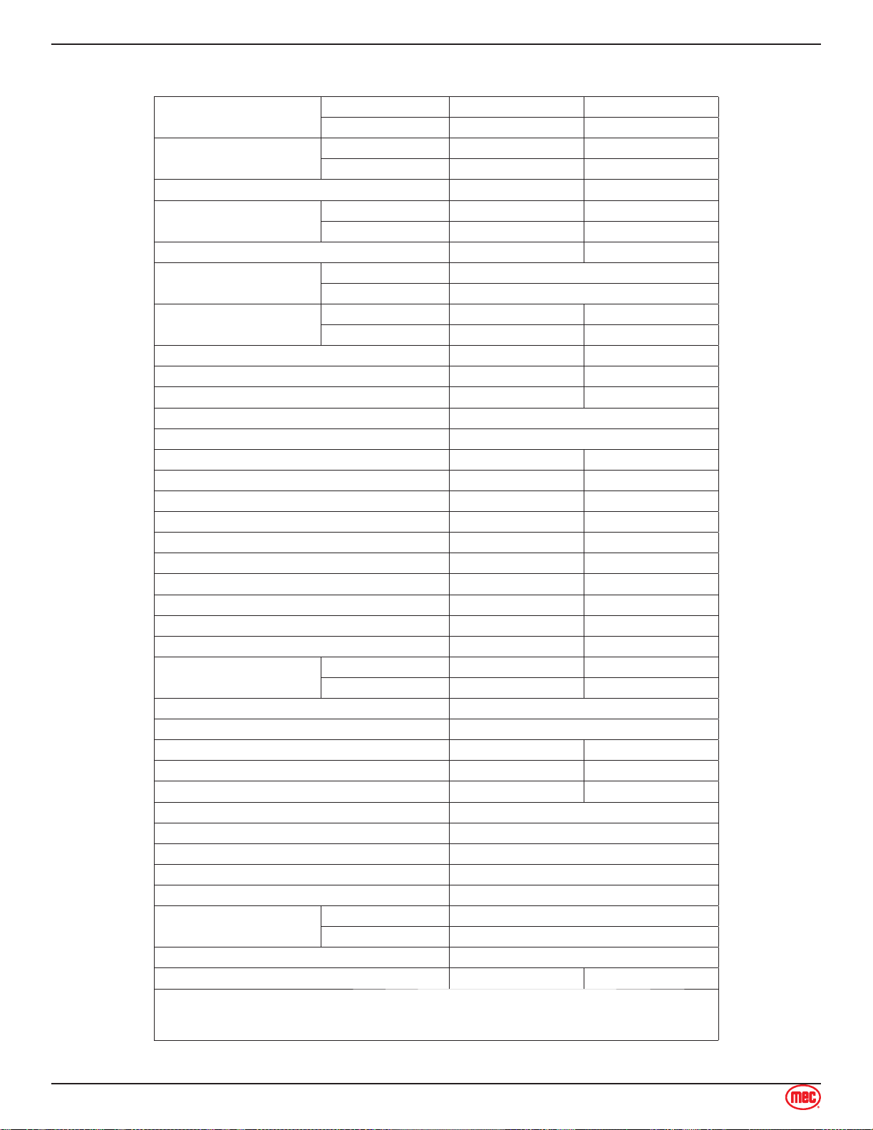
Specifications
Maximum Working Height* Indoor 19 ft 6 m
Outdoor 16 ft 4.9 m
Maximum Platform Height Indoor 13 ft 3.9 m
Outdoor 10 ft 3 M
Maximum Drive Height 13 ft 4 m
Stowed Height Top Guardrail 74 in 1.9 m
Platform Floor 35 in 0.9 m
Guardrail Height 39 in 1 m
Personnel Capacity Indoor 2
Outdoor 1
Manual Force Indoor 90 lbs 400 N
Outdoor 45 lbs 200 N
Toeboard Height 6 in 15 cm
Machine Weight** (Unloaded) 1,980 lbs 900 kg
Maximum Lift Capacity 500 lbs 227 kg
Deck Extension Capacity 1 Person / 250 lb (113 kg)
Maximum Occupants 2
Length-Stowed (Overall) 58 in 1.5 m
Length-Stowed (Ladder Removed) 51 in 1.3 m
Platform Length (Extended) 75 in 1.9 m
Platform Length (Retracted) 51 in 1.3 m
Width (Overall) 30 in 76 cm
Platform Width (Outside) 27.5 in 70 cm
Wheel Base 41 in 1 m
Turning Radius - Inside 18 in 45 cm
Ground Clearance - Stowed 2.5 in 6 cm
Ground Clearance - Elevated 0.6 in 1.5 cm
Drive Speed (Proportional) Stowed 0-2.5 mph 0-4.0 km/h
Raised or Extended 0-0.7 mph 0-1.1 km/h
Gradability 25%/14°
Maximum Side Slope - Stowed 5°
Ground Pressure/Wheel 112 psi 7.9 kg/cm2
Maximum Wheel Load 750 lbs 340 kg
Occupied Floor Pressure 234 psf 1,138 kg/m2
Maximum Operating Wind Speed 28 mph / 12.5 m/sec (45 km/h)
Tire Size 9 x 3 inch / 230 x 80mm
Lug Nut Torque 19 ft-lb / 25.5 Nm, secured with cotter pin
Hydraulic Pressure 2,250 psi / 155 bar
Power System Voltage 24 Volt DC
Battery Charger Input 110-230 V AC, 50-60 Hz
Output 24 Volt DC
Batteries Two 12-Volt deep cycle; 85Ah
Chassis Inclination 1.5 Side 3.0 Inline
Meets requirements of ANSI A92.20-2020 and CSA B354.6-2019.
*Working Height adds 6 feet (2 m) to platform height.
**Weight may increase with certain options.
Section 3 - Specifications Specifications