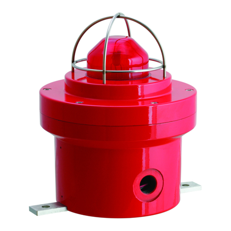
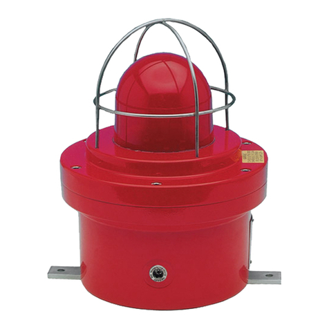
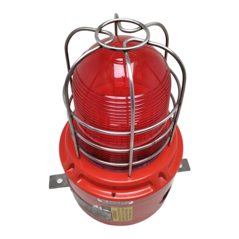
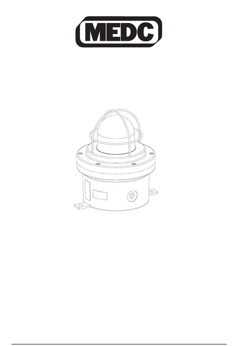
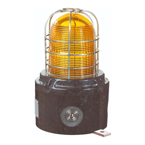
MEDC LD15 UL User manual

© MEDC 2018 01/18
Technical Manual for the LED Strobe LD15 UL/ULC
Please note that every care has been taken to ensure the accuracy of our technical manual. We do not, however,
accept responsibility for damage, loss or expense resulting from any error or omission. We reserve the right to make
alterations in line with technical advances and industry standards.
Veuillez noter que toutes les précautions ont été prises pour assurer l'exactitude de notre manuel technique.
Néanmoins, nous ne pouvons accepter la responsabilité pour les dommages, pertes ou dépenses découlant de toute
erreur ou omission. Nous nous réservons le droit d'apporter des modifications au fil des progrès techniques et des
normes de l'industrie.

01/18 © MEDC 2018

1.0 INTRODUCTION
These certified strobes have been designed for use in potentially explosive atmospheres and harsh environmental conditions.
The enclosures are suitable for use offshore or onshore, where light weight combined with corrosion resistance is required.
The housing is manufactured completely from a U.V. stable, glass reinforced polyester. Stainless steel screws and mounting
bracket are incorporated ensuring a totally corrosion free product.
Units can be painted to customer specification and supplied with identification labels.
2.0 GENERAL SAFETY MESSAGES AND WARNINGS
All instructions and safety messages in this manual must be followed to allow safe installation of the device. The device must
only be installed and maintained by correctly trained site personnel/installers.
i. To reduce the risk of ignition of hazardous atmospheres and shock, do not apply power to the device until
installation has been completed and the device is fully sealed and secured.
ii. To reduce the risk of ignition of hazardous atmospheres and shock, keep device tightly closed when the circuit is
energised.
iii. Before removing the cover for installation or maintenance, ensure that the power to the device is isolated.
iv. Following installation, test the device to ensure correct operation.
v. Following installation ensure a copy of this manual is made available to all operating personnel
vi. When installing the device, requirements for selection, installation and operation should be referred to e.g. IEE
Wiring Regulations and the ‘National Electrical Code’ in North America. Additional national and/or local
requirements may also apply.
vii. Cable termination should be in accordance with specification applying to the required application. MEDC
recommends that all cables and cores should be correctly identified. Please refer to the wiring diagram in this
manual (or separate diagram provided with the unit).
viii. Ensure that only the correct listed or certified cable glands are used and that the assembly is shrouded and
correctly earthed.
ix. Ensure that only the correct listed or certified stopping plugs are used to blank off unused gland entry points and
that the NEMA/IP rating of the unit is maintained.
x. MEDC recommend the use of a sealing compound such as HYLOMAR PL32 on the threads of all glands and
stopping plugs in order to maintain the IP rating of the unit.
xi. The internal earth terminal, where fitted, must be used for the equipment grounding and the external terminal, if
available, is for a supplementary bonding connection where local codes or authorities permit or require such a
connection.
xii. When installing the device, MEDC recommends the use of stainless steel fasteners. Ensure that all nuts, bolts and
fixings are secure.
xiii. To reduce the risk of ignition of hazardous atmospheres, conduit runs must have an appropriate UL or IECEx
certified sealing fitting connected at the conduit opening of the enclosure.
© MEDC 2018 01/18
xiv. AC units are not intended to be powered directly from a Notification Appliance Circuit.
3.0 INSTALLATION
Direct mount version
The device can either be directly mounted using the inserts moulded into the back of the enclosure (standard), or an optional
backstrap can be fixed to the base of the device thus giving an optional mounting position for when direct mounting is
deemed unsuitable.
The 2 off inserts in the base of the enclosure are designed to accept an M5 screw or bolt.
NOTE: For direct mounting, observe the following formula to determine the required fixing screw length:
Length of screw = Thickness of mounting surface + 25/64” (10mm).
The 2 off Ø21/64” (Ø8.5mm) mounting holes in the optional backstrap have been designed to accept an 5/16” (M8)
screw or bolt.
Pole mount version
The unit can be mounted to a ½” or ¾” conduit and may be positioned in any orientation. To mount the unit, thread fully
onto conduit and secure with the set screw provided (2.5mm A/F hexagon key).

Access to terminals & DIL switch
Ensure the cover seal is correctly seated in its groove during re-assembly. There should be a maximum gap of 0.0075”
(0.2mm) between the faces of the cover and enclosure to ensure o-ring compression.
01/18 © MEDC 2018

4.0 OPERATION
The operating voltage of the unit is stated on the unit label. The beacon can be powered directly or initiated by a
24Vdc relay or telephone ringing signal if requested when ordered.
Note: The unit complies with 24Vdc UL/ULC regulated power supplies
WIRING DETAIL – DIRECT MOUNT VERSIONS
WIRING DETAIL – POLE MOUNT VERSIONS
© MEDC 2018 01/18

WIRING DETAIL – RELAY INITIATE VERSIONS
01/18 © MEDC 2018
When installed as a direct switching device, the operating mode can be set by means of a 3 way DIL switch
mounted on the underside of the electronics assembly. The switch settings for the various modes of operation are as
follows:
Mode No. SW1 SW2 SW3 Function
0000Off / Rmote switching
1001120 fpm
201060 fpm (default)
301180 fpm
4100Steady
5101Double flash
Note: The default setting supplied by MEDC is 60 flashes per minute (0,1,0).
For the double flash function, the unit performs 40 double flashes per minute
The device can be configured for remote switching of the operating mode. The three way switch on the electronics
assembly must be set to off (0,0,0), then the operating mode can then be switched by closing one or more of the
control connections to the device. The combinations are as per the table above.
Note: The steady function (1,0,0) is not available on ULC certified units.
The operating voltage of the unit is stated on the label. The unit can be powered directly or initiated by a 24Vdc relay
if requested when ordered.
Note: The DC unit complies with 24Vdc UL/ULC regulated power supplies. The AC unit complies with 120Vac and
240Vac UL/ULC regulated power supplies.
Warning statements:
i. Seal all conduit entries.
ii. To avoid electrostatic build up, clean enclosure exterior with a damp cloth
iii. Do not open while energised
iv. Do not open when an explosive atmosphere may be present
v. A seal shall be installed within 50mm of the enclosure
vi. Flameproof joint between cover and enclosure - Threaded type with a minimum of five full thread engagement
for a minimum length of 10mm
vii. For supply connections, use minimum of 105°C rated wire.
viii. Not to be used as a visual public mode alarm notification appliance (UL version only)
ix. Fire alarm device - Do not paint (ULC version only)

GENERAL ARRANGEMENT
© MEDC 2018 01/18
Typical electrical ratings:
The following table shows the typical operating current range for each nominal voltage available. As the operating
current varies with the flash pattern selected, each unit will be marked with the worst case current.
See the certification label fitted to the enclosure.
NOMINAL
VOLTAGE
TYPICAL CURRENT
RANGE (A)
DC
12V 0.43 - 1.10
24V 0.22 - 0.42
48V 0.12 - 0.22
AC
110V 0.04 - 0.10
120V 0.04 - 0.10
230V 0.03 - 0.06
240V 0.03 - 0.06
254V 0.03 - 0.06

Typical certification label detail:
See below for a typical example of an LD15 UL certification label:
LIGHT OUTPUT RATING (Cd)
NO GUARD CAST GUARD WIRE GUARD
Colour
60, 80,
120fpm
Double
flash
60, 80,
120fpm
Double
flash
60, 80,
120fpm
Double
flash
Clear 48.6 26.6 29.7 15.3 38.7 20.7
Yellow 32.0 17.6 22.5 12.2 25.4 13.7
Red 25.2 13.5 15.8 8.6 20.1 10.5
Amber 18.9 10.8 11.7 5.9 15.1 8.4
Green 14.0 7.7 9.0 5.0 11.1 6.0
Blue 5.0 2.7 2.7 N/A* 3.9 2.1
* Note: The combination of double flash operation on a blue unit with a cast guard is not covered by the ULC listing.
AC Units:
* Note: Model variants with candela ratings below 15Cd are not for Public Mode use.
LIGHT OUTPUT RATING (Cd)
NO GUARD CAST GUARD WIRE GUARD
Colour
60, 80,
120fpm
Double
flash
60, 80,
120fpm
Double
flash
60, 80,
120fpm
Double
flash
Clear 68.0 37.2 38.0 20.3 50.0 25.8
Yellow 37.0 20.4 20.7 11.2 27.2 14.8
Red 12.0 7.0 7.3 3.8 9.6 5.2
Amber 8.0 6.9 6.7 3.7 8.8 4.4
Green 13.0 4.4 4.5 2.4 5.9 3.3
Blue 6.0 3.2 3.4 1.8 4.4 N/A
Light output ratings
DC Units:
01/18 © MEDC 2018

5.0 MAINTENANCE
During the working life of the unit, it should require little or no maintenance. GRP will resist attack by most acids, alkalis and
chemicals and is as resistant to concentrated acids and alkalis as most metal products.
However, if abnormal or unusual environmental conditions occur due to plant damage or accident etc., then visual inspection
is recommended.
If the unit requires cleaning, then only clean exterior with a damp cloth to avoid electro-static charge build up.
If a unit fault should occur, then the unit can be repaired by MEDC. All parts of the unit are replaceable.
If you acquired a significant quantity of units, then it is recommended that spares are also made available. Please discuss
your requirements with the Technical Sales Engineers at MEDC.
If required, replacement of the electronic sub-assembly can be carried out by competent site personnel. See previous page for
details of gaining access to the electronic sub-assembly. Other repairs should be undertaken by returning the unit to MEDC.
During maintenance, if the cover/lens assembly grease needs to be re-applied, a PFPE (Perfluoropolyether) based grease
such as KRYTOX GPL203 by DuPont of Perfluorolube 22/6 by Performance Fluids Ltd should be used, to prevent damage
to the O-ring.
6.0 SPECIAL CONDITIONS FOR SAFE USE
1. Painting and other surface finishes, other than those applied by the manufacturer, are not permitted
2. In order to maintain the dust tight integrity of the enclosures (IP6X), the threads of cable entry devices and stopping
plugs shall be sealed in accordance with the applicable code of practice for flameproof installation.
7.0 CERTIFICATION/APPROVALS
Please refer to the marking on the unit for specific approval details
T-rating (T
G
)T
amb.
T5 -67°F to +158°F (-55°C to +70°C)
T6 -67°F to +131°F (-55°C to +55°C)
UL certified for use in Class I, Div. 2, Groups A, B, C & D
USA (USL) and Canada (CNL) Class II, Div. 2, Groups F & G
Class I, Zone 1, AEx d IIC; Ex db IIC Gb
Standards UL 60079-0 6th Edition
UL 80079-1 6th Edition
UL 1638, 4th Edition
UL 1638a, 1st Edition
ANSI/ISA 12.12.01-2013
CSA-C22.2 No. 205
CSA-C22.2 No. 60079-0:15
CSA-C22.2 No. 60079-1:16
CSA-C22.2 No. 157-92
CAN/ULC-S526-07 Ed. 3
© MEDC 2018 01/18

8.0 FUNCTIONAL SAFETY
Introduction
The LD15 Beacon has been designed for use in potentially explosive atmospheres and harsh environmental conditions. The
glass reinforced polyester enclosures are suitable for use offshore or onshore, where light weight combined with corrosion
resistance is required.
The safety function of the Beacon is to provide an intermittent or permanent spherical visual warning light when the correct
voltage is applied to the unit. The Beacon is designed to operate on a supply voltage of 24vDC with a tolerance of +/- 20%.
01/18 © MEDC 2018
Under No fault (Normal) Operating conditions the LD15 Beacon will provide a spherical visual warning light when required
by the system, with no time delay or other faults.
Under fault conditions the failure mode of the Beacon is a failure to provide a spherical visual warning light. For the failure
rate associated with this failure mode please refer to the table below.
The DC version of the Beacon is designed to operate on a supply voltage of 11-58Vdc,
the AC version of the beacon is designed to operate on a supply voltage of 110-254Vac.
Assessment of Functional Safety
This Beacon is intended for use in a safety system conforming to the requirements of IEC61508.
Sira Test & certification Ltd has conducted a Failure Modes Effect and Diagnostic Analysis (FMEDA) of the LD15
Xenon Beacon against the requirements of IEC 61508-2 using a Proof Test Interval of 8760hrs.
The results are shown below and are based on Route 1H.
The Beacon is classed as a Type B device
Safety Function:
‘To provide an intermittent or permanent spherical visual warning light upon demand’.
Summary of Clauses
2/7.4.2 and 2/7.4.4
LD15 LED Beacon
Single Mode (1oo1)
LD15 LED Beacon
Redundant Mode (1oo2) Verdict
HFT=0 HFT=1 Type B
Architectural constraints
Safe Failure Fraction (SFF) 60% 60% SIL 1
Random hardware
failures: [h-1 ]
DD
DU
0.00E+00
3.44E-08
0.00E+00
3.45E-09
Random hardware
failures: [h-1 ]
SD
SU
0.00E+00
5.16E-08
0.00E+00
5.19E-09
Diagnostic coverage (DC) 0.00% 0.00%
PFD @ PTI = 8760Hrs
MTTR = 8 Hrs 1.51E-04 1.51E-05
Average freq. of dangerous failure
(high demand-PFH)[h-1]3.44E-08 3.45E-09
SIL 3
SIL 3
Hardware safety integrity
compliance[Route 1H
Systematic safety integrity
compliance See report R56A31253B
Systematic Capability
(SC1, SC2, SC3, SC4) SC2 (R56A31253B)
Hardware safety integrity achieved Limited to: SIL 1 (1oo1) & SIL 2 (1oo2) due to SFF value.
- LD15 DC

© MEDC 2018 01/18
Safety Function:
LD15 AC Beacon
Summary of Clauses
2/7.4.2 and 2/7.4.4
LD15 LED Beacon
Single Mode (1oo1)
LD15 LED Beacon
Redundant Mode (1oo2) Verdict
Architectural constraints
Safe Failure Fraction (SFF)
HFT=0 HFT=1 Type B
67% 67% SIL 1 (1oo1)
SIL 2 (1oo2)
Random hardware
failures: [h
-1
]
DD
DU
6.45E-09
6.247E-08
6.45E-10
6.247E-09
Random hardware
failures: [h
-1
]
SD
SU
0.00E+00
1.21E-07
0.00E+00
1.21E-08
Diagnostic coverage (DC) 0.00% 0.00%
PFD @ PTI = 8760Hrs, MTTR = 8 Hrs 2.74E-04 2.742E-05 SIL 3 (1oo1)
Average freq. of dangerous failure
(high demand-PFH)[h
-1
] 6.247E-08 6.247E-09 SIL 4 (1oo1)
Hardware safety integrity compliance Route 1
H
Systematic safety integrity compliance Route 1
S
Systematic Capability
(SC1, SC2, SC3, SC4)
SC2
Hardware safety integrity achieved Limited to: SIL 1 (1oo1) & SIL 2 (1oo2) due to SFF value.
Assessment of Functional Safety - LD15 AC
This Beacon is intended for use in a safety system conforming to the requirements of IEC61508.
UL has conducted a Failure Modes Effect and Diagnostic Analysis (FMEDA) of the LD15 LED Beacon against the
requirements of IEC 61508-2 using a Proof Test interval of 8760hrs.
The results are shown below and are based on Route 1H.
The Beacon is classed as a Type B device.

Conditions of Safe use
The following conditions apply to the installation, operation and maintenance of the LD15. Failure to observe these
may compromise the safety integrity of the Beacon
1. The user shall comply with the requirements given in this Safety manual in regard to all relevant functional
safety aspects such as application of use, installation, operation, maintenance, proof tests,maximum
ratings, environmental conditions, repair, etc.
2. If the Beacon is to be used on a Fire Alarm system it is recommended as per BS 5839 part 1 (eq. EN 54),
that the product is tested at least once a week. In all other applications it is strongly recommended to test
the product at least once a year.
3. Selection of this equipment for use in safety functions and the installation, configuration, overall validation,
maintenance and repair shall only be carried out by competent personnel, observing all the manufacturer’s
conditions and recommendations in the user documentation.
4. All information associated with any field failures of this product should be collected under a dependability
management process (e.g., IEC 60300-3-2) and reported to the manufacturer.
01/18 © MEDC 2018

1.0 INTRODUCTION
Ces feux à éclats certifiés ont été conçus pour une utilisation dans des atmosphères potentiellement explosives et des
conditions environnementales difficiles. Les boîtiers sont adaptés pour une utilisation marine ou terrestre, où le poids
léger combiné avec la résistance à la corrosion sont requis.
Le boîtier est fabriqué entièrement à partir d'un polyester stable aux UV, renforcé de verre. Des vis et le support de
montage tous deux en acier inoxydable sont incorporés assurant un produit totalement sans corrosion.
Les unités peuvent être peintes aux spécifications du client et fournies avec des étiquettes d'identification.
2.0 MESSAGES ET MISES EN GARDE GÉNÉRALES DE SÉCURITÉ
Toutes les instructions et les messages de sécurité dans ce manuel doivent être suivies pour permettre l'installation
sécuritaire de l'appareil. L'appareil ne doit être installé et entretenu que par du personnel correctement formé sur site /
des installateurs.
Pour réduire le risque d'inflammation d'atmosphères dangereuses et les chocs, ne pas brancher l'appareil jusqu'à ce que
l'installation ait été achevée et que le dispositif soit entièrement étanche et sécurisé.
Pour réduire le risque d'inflammation d'atmosphères dangereuses et les chocs, conserver l'appareil hermétiquement fermé
lorsque le circuit est sous tension.
Avant de retirer le couvercle pour l'installation ou l'entretien, veiller à ce que l'appareil soit débranché.
Après l'installation, tester le dispositif pour assurer un fonctionnement correct.
Après l'installation, s'assurer qu'une copie de ce manuel est mise à la disposition de tout le personnel d'exploitation.
Lors de l'installation de l'appareil, les exigences pour la sélection, l'installation et le fonctionnement doivent se faire
conformément aux règlements IEE et du "National Electrical Code" en Amérique du Nord. Des exigences nationales et / ou
locales supplémentaires peuvent s'appliquer.
La connexion des câbles doit être conforme aux spécifications s'appliquant à l'application requise. MEDC recommande
que tous les câbles et fils doivent être correctement identifiés. Veuillez consulter le schéma de câblage dans le manuel (ou
diagramme séparé fourni avec l'unité).
Veiller à ce que seuls les presse-étoupes certifiés ou répertoriés corrects sont utilisées et que l'ensemble est protégé et
correctement mis à la terre.
S'assurer que seuls les bouchons répertoriés corrects ou certifiés sont utilisés pour obturer les points d'entrée des presse-
étoupes inutilisés et que l'indice IP NEMA de l'unité est maintenu.
MEDC recommande l'utilisation d'un produit d'étanchéité type HYLOMAR PL32 sur les filets de tous les presse-étoupes et
bouchons afin de maintenir l'indice IP NEMA de l'unité.
La borne interne de mise à la terre, lorsque l'appareil en est équipé, doit être utilisée pour la mise à la terre de
l'équipement et le terminal externe, si disponible, est prévu pour une connexion supplémentaire si les codes locaux ou les
autorités compétentes autorisent ou exigent une telle connexion.
Lors de l'installation de l'appareil, MEDC recommande l'utilisation d'éléments de fixation en acier inoxydable. S'assurer
que tous les écrous, boulons et fixations sont sécurisés.
Pour réduire le risque d'inflammation des atmosphères dangereuses, les courses de conduite doivent posséder un raccord
d'étanchéité certifié UL ou IECEx connecté à l'orifice du conduit du boîtier.
i.
ii.
iii.
iv.
v.
vi.
vii.
viii.
ix.
x.
xi.
xii.
xiii.
FRANÇAIS
© MEDC 2018 01/18
xiv. Les unités à courant alternatif (C.A.) ne sont pas destinées à être alimentées directement par un circuit d'appareil
de notification.
Version montage direct
Le dispositif peut être directement monté en utilisant les inserts moulés à l'arrière de l'enceinte (standard), ou une bride
arrière optionnelle peut être fixée à la base de l'appareil donnant ainsi une position de montage en option lorsque le
montage direct est jugé inadapté.
Les 2 inserts dans la base de l'enceinte sont conçus pour accepter une vis ou un boulon M5.
REMARQUE : Pour le montage direct, respecter la formule suivante pour déterminer la longueur de la vis de fixation
nécessaire :
Longueur de vis = épaisseur de la surface de montage + 25/64" (10 mm).
Les deux trous de montage Ø21/64" (Ø8,5 mm) dans la bride arrière optionnelle ont été conçus pour accepter une vis
ou un boulon 5/16" (M8).
Version montage sur poteau
L'unité peut être montée sur un poteau de ½" ou ¾" et peut être placée dans n'importe quelle orientation. Pour monter
l'appareil, visser à fond sur le conduit et le fixer avec la vis de fixation fournie (2,5 mm clé hexagonale A/F).
3.0 INSTALLATION

Accès aux bornes & commutateur DIL.
Vérifier que le joint du couvercle est correctement inséré dans son logement lors du remontage. Il devrait y avoir un
écart maximum de 0,0075 "(0,2 mm) entre les faces de la couverture et de l'enceinte pour assurer la compression du
joint torique.
01/18 © MEDC 2018

4.0 FONCTIONNEMENT
La tension de fonctionnemen
t
o
sur commande au m
o
y
en d'
u
Remarque
c
: L'unité est
o
o
nfor
T
DÉ
TA
A
de l'unité est indiquée sur l'étiquette d'un
u
nrelais24VCC
me aux alimentations régulées UL/ULC e
n
L
A
ILS DU CÂB
A
A
GE - VERSIO
N
T
ité. L'équipement peut être alimenté direc
t
n
24 V c.c.
N
SMON
TA
AG
EDIRECT
t
ement ou
T
MON
TA
A
GE SUR POTEAU
L
T
DÉ
TA
A
ILS DU CÂB
LA
A
GE
-
VERSIONS M
L
T
DÉ
TA
A
ILS DU CÂB
LA
A
GE
VERSIONS M
T
MON
TA
A
GE
SUR
POTEAU
© MEDC 2018 01/18

DÉTAILS DU CÂBLAGE - VERSIONS AVEC RELAIS LANCER OPTION
Lorsqu'il est installé comme un dispositif de commutation directe, le mode de fonctionnement peut être défini au moyen d'un
commutateur DIL 3 voies monté sur la face inférieure de l'assemblage électronique. La position des interrupteurs pour les
différents modes de fonctionnement sont les suivantes :
01/18 © MEDC 2018
L'unité à C.A. est conforme aux alimentations électriques régulées UL/ULC en 120 V c.a. et en 240 V c.a.
Déclarations d'avertissement:
i. Scellez toutes les entrées de conduits
ii. Pour éviter l’accumulation électrostatique, nettoyez l’extérieur du boîtier avec un chiffon humide
iii. Ne pas ouvrir lorsque sous tension
iv. Ne pas ouvrir quand une atmosphère explosive peut être présente
v. Un joint doit être installé à l'intérieur de 50 mm du boîtier
vi. Joint antidéflagrant entre le couvercle et le boîtier - Type fileté avec un minimum de cinq filets complets en prise
pour une longueur minimale de 10 mm
vii. Pour les connexions d'alimentation, utilisez un fil avec une valeur nominale minimum de 105 °C.
viii. Ne doivent pas être utilisées comme un appareil de notification d'alarme en mode public visuel (version UL
seulement)
ix. Dispositif d'alarme incendie - Ne pas peindre (version ULC seulement)
Mode N° SW1 SW2 SW3 Fonction
0000Off / commutation
distante
1001120 fpm
201060 fpm (par défaut)
301180 fpm
4100Fixe
5101Double flash
Remarque : Le paramètre par défaut fourni par MEDC est 60 clignotements par minute (0,1,0).
Pour la fonction double flash, l'unité effectue 40 double flash par minute
L'appareil peut être configuré pour la commutation distante du mode de fonctionnement. Le commutateur trois voies sur le
bloc électronique doit être défini à off (0,0,0), puis le mode de fonctionnement peut être commuté en en fermant une ou
plusieurs des connexions de contrôle de l'appareil. Les combinaisons sont conformément au tableau ci-dessus.
Remarque: La fonction fixe (1,0,0) n'est pas disponible sur les appareils certifiés ULC

DISPOSITION GÉNÉRALE
© MEDC 2018 01/18
Caractéristiques électriques typiques:
Le tableau suivant montre la plage réelle de fonctionnement typique pour chaque tension nominale disponible. Comme le
courant de fonctionnement varie avec la séquence de clignotement sélectionnée, chaque unité sera marquée avec le
courant de pire cas.
Reportez-vous à l'étiquette de certification montée sur le boîtier.
EKD/E>
'DDKhZEd
ϭϮs ϬϰϯͲϭϭϬ
Ϯϰs ϬϮϮͲϬϰϮ
ϰϴs ϬϭϮͲϬϮϮ
ϭϭϬs ϬϬϰͲϬϭϬ
ϭϮϬs ϬϬϰͲϬϭϬ
ϮϯϬs ϬϬϯͲϬϬϲ
ϮϰϬs ϬϬϯͲϬϬϲ
Ϯϱϰs ϬϬϯͲϬϬϲ

Valeurs nominales de lumière de sortie
LUMIÈRE DE SORTIE NOMINALE (Cd)
PAS DE PROTECTION PROTECTION MOULÉE DISPOSITIF DE
PROTECTION
Couleur
60, 80,
120 fpm
Double
flash
60, 80,
120 fpm
Double
flash
60, 80,
120 fpm Double flash
Clair 48,6 26,6 29,7 15,3 38,7 20,7
Jaune 32,0 17,6 22,5 12,2 25,4 13,7
Rouge 25,2 13,5 15,8 8,6 20,1 10,5
Ambre 18,9 10,8 11,7 5,9 15,1 8,4
Vert 14,0 7,7 9,0 5,0 11,1 6,0
Bleu 5,0 2,7 2,7 S/O 3,9 2,1
* Remarque: La combinaison du fonctionnement double flash sur une unité bleu avec une protection moulée n'est pas
couverte par ULC.
Détail de l'étiquette de certification typique:
Voir ci-dessous un exemple typique d'une étiquette de certification LD15 UL:
Unités à C.A.:
* Remarque: Les variantes de modèle avec des valeurs nominales en candela en dessous de 15 cd ne sont pas pour
l'utilisation en mode public.
SORTIE DE LUMIERE NOMINALE (Cd)
PAS DE PROTECTION PROTECTION MOULEE CAGE DE PROTECTION
Couleur 60, 80,
120fpm
Double
flash
60, 80,
120fpm
Double
flash
60, 80,
120fpm
Double
flash
Transparente
68.0 37.2 38.0 20.3 50.0 25.8
Jaune 37.0 20.4 20.7 11.2 27.2 14.8
Rouge 12.0 7.0 7.3 3.8 9.6 5.2
Ambre 8.0 6.9 6.7 3.7 8.8 4.4
Verte 13.0 4.4 4.5 2.4 5.9 3.3
Bleue 6.0 3.2 3.4 1.8 4.4 S.O.
01/18 © MEDC 2018
Unités à C.C.:

5.0 ENTRETIEN
Pendant la durée de vie de l'unité, celle-ci devrait exiger peu ou pas d'entretien. GRP résistera à l'attaque de la plupart
des acides, des alcalis et des produits chimiques et est aussi résistant aux acides et aux alcalis concentrés comme la
plupart des produits métalliques.
Toutefois, si des conditions environnementales anormales ou inhabituelles se produisent en raison de dommages à
l'installation ou d'accident, etc., alors un contrôle visuel est recommandé.
Si l'unité nécessite un nettoyage, alors nettoyer seulement l'extérieur avec un chiffon humide pour éviter l'accumulation
de charges électrostatiques.
En cas de panne, l'unité peut être réparée par MEDC. Toutes les parties de l'unité sont remplaçables.
Si vous avez acquis une importante quantité d'unités, il est alors recommandé de prévoir des pièces de rechange
disponibles. Veuillez discuter de vos besoins avec les ingénieurs technico-commerciaux de MEDC.
Si nécessaire, le remplacement du sous-ensemble électronique peut être effectué par un personnel compétent du site. Voir
la page précédente pour plus de détails sur l'accès au sous-ensemble électronique. Les autres réparations devront être
effectuées via un retour de l'unité à MEDC.
Pendant la maintenance, si de la graisse doit être de nouveau appliquée sur l'ensemble capot/lentille, une graisse à base
de PFPE (perfluoropolyéther) comme du KRYTOX GPL203 par Dupont ou de perfluorolube 22/6 par Performance Fluids
Ltd doit être utilisée, pour éviter d'endommager le joint torique..
Certifié UL pour utilisation dans Classe I, Div. 2, Groupes A, B, C et D
USA (USL) et Canada (CNL) Classe II, Div. 2, Groupes F et G
Classe I, Zone 1, AEx d IIC; Ex db IIC Gb
Normes UL 60079-0 6ème édition
UL 80079-1 6ème édition
UL 1638, 4ème édition
UL 1638a, 1ère édition
ANSI/ISA 12.12.01-2013
CSA-C22.2 N° 205
CSA-C22.2 N° 60079-0:15
CSA-C22.2 N° 60079-1:16
CSA-C22.2 N° 157-92
CAN/ULC-S526-07 Éd. 3
CONDITIONS SPÉCIALES POUR UNE UTILISATION SÛRE
La peinture ou autres finitions de surface, différentes de celles qui sont appliquées par le fabricant, ne sont pas
autorisées
Afin de maintenir l'intégrité de l'étanchéité à la poussière des boîtiers (IP6X), le filetage du câble entrée appareil
et celui des bouchons d'arrêt doivent être scellés conformément aux dispositions du code de bonne pratique
applicable à une installation antidéflagrante.
7.0 CERTIFICATION/APPROBATIONS
Veuillez vous référer au marquage sur l'unité pour plus de détails des approbations spécifiques
6.0
1.
2.
T-nominale
(TG)Tamb.
T5 -67 °F à +158 °F (-55 °C à +70 °C)
T6 -67 °F à +131°F (-55 °C à +55°C)
© MEDC 2018 01/18

8.0 SÉCURITÉ FONCTIONNELLE
Introduction
Le balise stroboscopique LD15 a été conçu pour une utilisation dans des atmosphères potentiellement explosives et des
conditions environnementales difficiles. Les boîtiers en polyester renforcé de fibre de verre sont adaptés pour une
utilisation marine ou terrestre, où un poids léger combiné avec une résistance à la corrosion sont requis.
La fonction de sécurité du balise stroboscopique est de fournir un avertissement visuel sphérique en lumière intermittente
lorsque la tension correcte est appliquée à l'unité. La balise stroboscopique est conçue pour fonctionner avec une tension
d'alimentation de 24 V c.c. avec une tolérance de + /- 20 %.
En conditions d'exploitation sans défaut (Normal), le balise stroboscopique LD15 fournira un avertissement visuel
sphérique lorsque requis par le système, sans délai ou autres fautes.
01/18 © MEDC 2018
Et la version à C.A. de la balise est conçue pour
fonctionner sur une tension d'alimentation de 110 à 254 V c.a.
En conditions d'exploitation défaillantes, le mode échec du balise stroboscopique est l'échec de la fourniture de
l'avertissement visuel sphérique. Pour le taux d'échec associé à ce mode de défaillance, veuillez consulter le tableau ci-
dessous.
Évaluation de la sécurité fonctionnelle
Ce balise stroboscopique est destiné à une utilisation dans un système de sécurité conforme aux exigences IEC61508.
Sira Test & certification Ltd a mené une étude FMEDA (Failure Modes Effect and Diagnostic Analysis) (Analyse et
diagnostic de modes de défaillance et de leurs effets) de la version c.c. du balise stroboscopique au xénon LD15 vis-à-
vis des exigences de la norme IEC 61508-2, en utilisant un intervalle d'épreuve de 8760 h.
Les résultats sont indiqués ci-dessous et sont basés sur la Route 1 H.
Le balise stroboscopique est classé comme un appareil de type B
Fonction de sécurité :
"De fournir un témoin visuel sphérique d'avertissement intermittent ou permanent à la demande".
Récapitulatif des Clauses
2/7.4,2 et 2/7 4,4
Balise stroboscopique à
LED LD15
Mode simple (1oo1)
Balise stroboscopique à
LED LD15
Mode redondant (1oo2)
Verdict
HFT=0 HFT=1 Type B
Contraintes d'architecture
Safe Failure Fraction (SFF) (Fraction
d'échec de sécurité) 60 % 60% SIL 1
Défaillances aléatoires du
matériel : [h-1 ]
DD
DU
0.00E+00
3.44E-08
0.00E+00
3.45E-09
Défaillances aléatoires du
matériel : [h-1 ]
SD
SU
0.00E+00
5.16E-08
0.00E+00
5.19E-09
Couverture de Diagnostic (DC) 0,00 % 0,00 %
PFD @ PTI = 8760 h
MTTR = 8 h 1.51E-04 1.51E-05
Fréquence moyenne de défaillance
dangereuse (forte demande de PFH)
[h-1]
3.44E-08 3.45E-09
SIL 3
SIL 3
Conformité de la sécurité intégrité
du matériel[Route 1H
Conformité de la sécurité intégrité
systématique Voir rapport R56A31253B
Capacité systématique
(SC1, SC2, SC3, SC4) SC2 (R56A31253B)
Intégrité de sécurité du matériel
atteinte limitée à: SIL 1 (1oo1) & SIL 2 (1oo2) dû à la valeur SFF.
- LD15 C.C.
This manual suits for next models
1
Table of contents
Languages:
Other MEDC Security System manuals
Popular Security System manuals by other brands

Seal One
Seal One 3200K user manual

Sirena
Sirena FieldServer FS-X20 Series Startup guide

AJAX Systems
AJAX Systems HomeSiren user manual

Swann
Swann Fourtify quick start guide

Tecnoalarm
Tecnoalarm TP8-64 user manual

Federal Signal Corporation
Federal Signal Corporation Commander 371ST-250 Installation and maintenance manual