Medem SafeAir User manual

1
04/06/2018
SafeAir (GP)
Installation Instructions
The SafeAir (GP) is a ventilation interlock and gas ressure roving system with gas detection.
The system will ensure that any mechanical ventilation connected (su ly and/or extract) is running before
the gas can be used, when installed with gas sensors it will also monitor the atmos here for CO and/or CO2.
It will then continually monitor for fan o eration.
The system will also ensure there are no gas leaks downstream of the control valve at switch on by way of a
downstream integrity check, It continually checks that the incoming gas ressure is sufficient.
Before commencing installation lease familiarise yourself to the equi ment by reading the com rehensive
installation instructions. If in doubt then lease call 0161 233 0600. Out of hours lease call 07894 684080 or
07843 355163.
It is a statutory requirement that this safety system is installed and commissioned
to the satisfaction of the manufacturer.
A commissioning certificate must be issued to the end user along with instructions for the o eration of the
equi ment.
As the Manufacturer Medem UK should commission this safety system whereu on a commissioning re ort
will be forwarded to the installing agent who should rovide a co y to the end user.
At the oint of our commissioning an individual serial number will be attached to the system along with a 24
hel line number. Photos and all relevant information for the installation will then be stored on the Medem
site database to be accessed in the event of a call on the 24 hour hel line. The warranty eriod for the
anel and sender unit will then be extended to Ten years.
• Gas Pressure roving.
• Gas Detection .(u to 4 detectors )
• Fan interlock.
• 5 year warranty - 10 years when commissioned
SafeAir (GP) features

2
04/06/2018
System descri tion
SafeAir (GP)
System On/Off enables gas detection and use of
each service button
Multi gas detection, air quality monitor and gas ressure roving system
The SafeAir (GP) is a Ventilation Interlock and Gas Pressure Proving system. The system will ensure that any mechanical
ventilation connected (su ly or extract) is running before the gas can be used, when installed with gas sensors it will also
monitor the atmos here for CO and/or CO2. It will then continually monitor for fan o eration.
The system will also ensure there are no gas leaks downstream of the control valve at switch on by way of a downstream
integrity check, It continually checks that the incoming gas ressure is sufficient.
The system com rises of a mains owered anel ca able of o erating u to four sensors and a ressure sender unit. The
sensors are re-calibrated by Medem (UK) Ltd such that they only require to be addressed then connected to the anel and
functionally tested. The ventilation is interlocked via a MEDEM current monitor model CM2M-K (se arate) or mechanical air flow
switches.
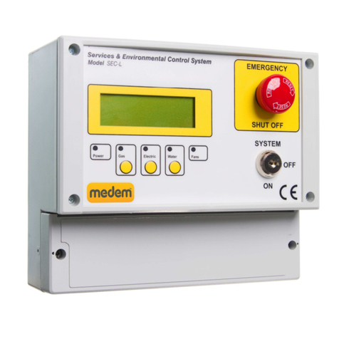
Control Panel
The front of the anel has the following controls and indications:
Emergency sto button.
System On/Off switch.
LCD dis lay:
For dis laying system status during both installation and normal use, also for dis laying diagnostics
Pressure sender unit transmits ressure information back to the main anel in order for it to reform its integrity test. Its is not
o tional and must be connected, the system will not work without it.
It is mounted to the gas solenoid valve inlet and outlet test orts using 8mm OD co er i e. Use the a ro riate Medem fitting
kit to fit the control valve size (see age 7,8).
The ressure sender is connected to the control anel with low voltage two core cable using the terminal marked A & B.
NO E: his is low voltage and should be segregated from mains wiring.
Pressure Sender Unit

3
04/06/2018
Main features
SafeAir (GP)
1 2
12 11
16
17
13
14
3 4 5 6 7 8 9 10
18
19
15
20
Connections to anel: marked on board.
1. Live & Neutral 230 volts su ly from 3am switched fuse s ur
2. 230 volts out to gas solenoid valve
3. Earth connection terminals
4. BMS to indicate, high alarm, gas on, EM sto , low alarm. (Using No13 AX1 & 2 )
00 = Gas On
10 = Fan Fault
01 = EM Sto & High Alarm
11 = Unused
5. Remote emergency sto buttons SELV, connect in series multi le buttons (requires a N/C circuit)
6. Power connections for detectors, Methane, LPG, CO, CO2, Oxygen, Tem erature
7. Comms connections for detectors, Methane, LPG, CO, CO2, Oxygen, Tem erature
8. 12 volt ower for current monitor (CM2M-K)
9. Fan A interlock for current monitor (CM2M-K) or PD switches.
10.Fan B interlock for current monitor (CM2M-K) or PD switches.
11. Switch to disable audible alarm sounder.
12. Header socket for front anel key switch.
13. Fill & rove time for gas ressure roving & AUX relay settings (see No4).
14. Header socket for front anel Emergency sto button.
15. Fan comm button, enables commissioning of the gas su ly without fans running.
16. Learn detectors button, ress once only when all detectors are connected and owered
17. View detectors
18. Dis lay gas ressures on the LCD screen
19. Lift valve button, o ens the gas valve only whilst the button is continuously ressed, for commissioning ur oses.
20.Pressure sender unit SELV and comm’s both through “A” & “B” terminals (2 wire) MUST BE FITTED

4
04/06/2018
Gas Detection
Gas Detectors
IMPORTANT - Gas Detectors should not be installed until all building, construction or ainting work etc.. Is com leted, as these
works can effect the sensitivity and longevity of the detectors.
Ensure that the rotective cover labels (RED) are removed only
after the com letion of all building work and the system has
been commissioned by the Medem engineer.
The labels are required to be removed for the detectors to
o erate, but removal before the com letion of works risks
contaminating the sensor element.
The system is ca able of o erating a mix of u to 4 detectors of different ty es.
The detector ty es are:
• Carbon Dioxide.
• Carbon Monoxide.
• Combustible gases (Methane, Pro ane).
Detector location will vary de endant on the individual characteristics of the target gas that is being monitored for. See the gas
detectors own instructions for more guidance.
Detector Information
+VE su ly & Comm’s
From either the main anel or an
extender.
Detectors are wired in arallel and can be
connected to one another daisy chain
Address Selector
Each detector must be set to its own
address and then “learnt” using button
16 (see age 3)
Connection and addressing
Status LED
SafeAir (GP)
All current wiring regulations must be followed with reference to running low and mains voltage cables together.
The maximum cable length between a detector and the control anel should not exceed 100 metres, if the distance between
the main anel and the detectors is greater than 20metres a 1mm screened cable must be used on the +VE, 0v terminals
Gas detectors, require a four core screened Belden ty e security cable or 600v rated BMS cable (max cable length of
100meters.)
Pressure sender unit, remote emergency sto s, require a two core screened cable.
Warranty will be void if Fire Protection Cable or cable over 1mm dia. is used on the SELV side.

5
04/06/2018
Detector Information
Detector location will vary de endant on the individual characteristics of the target gas that is being monitored for.
The descri tions below describe the osition for each detector after considering these characteristics.
For ro er function care must be taken not to site a detector in a “dead s ace” or in the flow of any ventilation.
Natural Gas/Methane
Natural gas detectors should be mounted at high level on a wall a roximately 150mm from the ceiling height and avoiding
corners and otential dead air areas.
Natural gas detectors should not be mounted below the height of the to of a doorway for exam le. This is because as the gas
is slightly lighter than air it will rise filling the room from the ceiling down and will s ill through the to of a door o ening into the
next room. If the detectors are mounted below this height then it will take longer the gas to reach the detector.
LPG /Propane
LPG gas is heavier than air so detectors need to be mounted at low level 100mm from the floor, consideration should be given
to any otential mo ing or wet floor height.
Carbon Monoxide
Carbon Monoxide is similarly weighted to air so detectors should be mounted between 1 to 2 meters from the floor.
Carbon Dioxide
Carbon Dioxide detectors should be installed so they monitor the general level of CO2 within the area. They should be mounted
above standing head height and between 1m and 3m from the otential source. Care should be taken so they are not located
close to the edge of a cano y or in direct flow of the su ly or extract ventilation.
For additional information or guidance on site s ecific requirements lease don’t hesitate to contact us.
Each detector has its own Bi-Colour LED which is used to indicate the status of that detector.
Not Lit: No ower/comm’s. These a four wire units and all connections are required, check the olarity of both the
ower and the comm’s (MA/MB) terminals are correct.
Flashing Green: Detector is warming u , the detectors will flash green on ower u for 90 seconds while the sensor
elements stabilize. The system will ignore any detectors while flashing.
Solid Green: Detector is owered and active. Note: The detectors will still require correctly addressing (using the address
selector ot) and learning by the system using button 16 (see age 3).
Flashing Red: Low level alarm. All detectors have both a low and high level alarm, low level alarms serve as a warning
that an unsafe condition maybe building and gives chance to intervene before loss of gas service.
Solid Red High level alarm. An unsafe level of the target gas have been reached and the system will isolate the
gas su ly. The cause of the alarm will require identifying and resolving before the gas su ly can be re-
established.
After installation a sim le bum test can be erformed by using an a ro riate level test gas in order to check o eration. Full
testing and calibration checking takes lace during a Medem commissioning.
Detector Location
Detector Indications
SafeAir (GP)

6
04/06/2018
230v Su ly
3Am Fused S ur
Basic Connections
EM Sto Buttons,
Thermal links
(Normally closed)
For multi le, connect in
series.
Pressure Sender unit
mounts on to the body of the gas
valve
(Required)
Gas Solenoid
Medem
Gas detectors
Multi le,
connect in
arrallel
Live feed through the
Medem CM2M-K2 channel
current Monitor
fans Fan s eed
controls Fan live
Su ly
Where using 3 hase fans
interlock on a single hase
See age nine
Earth Connections not shown
Two core low voltage connection
6 core low voltage
+/- 12v Power
S1 = Su ly Fan N/C contact
E1 = Extract Fan N/C contact
Fan Interlock Connections
SafeAir (GP)

7
04/06/2018
Pressure Sender & Valve connection
Incorrect
Ensure that the valve is correctly installed with regard to the direction of the flow of gas and that the Sender Unit is fitted the
correct way round. (Note: there is no flow “through” the ressure sender unit, it is urely reading the ressures either side of the
valve.
Correct
Pressur
e
Solenoid
Never mount the valve such that the Solenoid or Sender Unit are below the horizontal.
Inlet Side/U stream Outlet Side/Downstream
Direction of flow
Gas Solenoid and Sender Unit Mounting
Pressure sender unit
SafeAir (GP)

8
04/06/2018
Fitting Kit
OUTLET PORT
Note: If this ort is blanked off,
use ort on base of valve.
WALL MOUNTING STRAP
NOTES:
Solenoid coil of the valve should never be mounted below the horizontal.
Pressure sender unit should never be mounted u side down (to rotect from water ingress)
A rox 400mm length
INLET PORT & OUTLET PORT
Note: These orts could be
side by side
Mounting details - Fitting kit
PRESSURE SENDER UNIT
INLET PORT
Fitting kit - Contents
SafeAir (GP)

9
04/06/2018
Remote sto buttons
To EM Sto connections in the
anel
Use terminals TB2 A & C Use terminals TB2 A & C
Remote sto buttons can be connected to the anel terminal
marked as “EM STOP” (number 6 ).
The remote buttons must be wired as shown in order to rovide a
“closed contact” for the control anel.
If thermal links are to be installed these should be wired
in series with the EM stop buttons
To EM Sto connections in the
anel
Indicator bar shows when
ressed
Normal EM-Sto Activated
Multiple Stop Buttons
Single Stop Buttons
Resetting (indicator bar)
The sto buttons su lied by Medem are of a “Push Glass, key resettable” style, when activated a yellow indicator bar will
show and the unit will require resetting using the key rovided.
Multi le sto buttons are wired in series.
If thermal links are to be installed these too should
be wired in series with the EM sto buttons
Use terminal TB2 A & C
SafeAir (GP)

10
04/06/2018
Warranty
Medem (UK) Limited
Project House
19 Dallimore Road
Manchester
M23 9NX
Tel: (0) 161 233 0600
Fax: (0) 161 233 0601
Web: www.medem.co.uk
E-mail: sales@medem.co.uk
Medem UK Warranty
Terms & Conditions
1. The warranty is a arts warranty and Medem UK Ltd will not cover or acce t any labour or
other ex enses that may be incurred in the rocess of changing faulty roduct.
2. All anels and sender units are covered by a five year warranty.
3. Gas detector units and other remote detectors carry a two year warranty. Installation of the
detectors should not be undertaken until all building and construction work is com leted.
4. Gas solenoid valves carry the original manufacturers warranty, though as the su lier
Medem UK will exchange faulty valves for return to the manufacturer.
5. Where a Medem UK engineer (or another com any a ointed by Medem UK) commission
and installed system then that system will carry a ten year warranty. This a lies to the
main anel and the sender unit. At the time of commissioning a security label with a serial
number will be attached to the main anel box. hotogra hs and a com rehensive record
of the installation will be held by Medem UK.
6. Where a warranty claim is made then, where a ro riate, a written order to attend site
must be rovided to Medem UK A cost for labour and travel to site will be re ared as a
quote. The cost must be included in the order.
7. Where it is found that the installation and/or the quality of workmanshi has contributed to
or wholly caused the failure of the roduct then we reserve the right to charge the whole or
a ro ortion of the cost of the faulty item.
SafeAir (GP)

11
04/06/2018
messages
est fail check all appliances are off and retest:
The system has found an esca e of gas, the most common cause is an o en a liance. Check all a liances are off and restart
the ressure test. If the system still re orts test fail then a leak will be on the i e work. Using “Blind button A” (see age 2) you
can view the gas ressures at the valve, the outlet ressure must remain at least 90% of the value of the inlet ressure or a leak
will be declared.
Sender error, call engineer
System is not receiving data from the sender unit. The ressure sender is a required art of the system and cannot be “linked
out”. Verify the sender is correctly wired and that you have a green flashing LED on the sender unit.
Detector fault, DXX lost comms
The system believes it has lost connection to a detector on address XX, verify detector addresses and ress the “learn
button” (16). Verify all connected detectors are being registered by ressing “blind button B” (see age 2). If you have no
detectors connected to the system ressing the learn button will clear the error message.
Gas Off, Switch On Fan X.
The system can monitor the fan status via a current monitor or air ressure switches. These rovide a closed contact to
terminals Fan A and Fan B, it is a requirement when using fan interlocking that the fans be running (and therefore the A and B1
receiving a closed contact) before the system can begin a gas ressure test. If at any oint the fans sto running (o ening the A
or B contact) the system will isolate the gas and re ort fans not running. Check that the fans are not only switched on, but
actually running and moving air.
Prs X.XMbar, Check Inlet Gas
The system requires a minimum of 13 mBar of ressure at the inlet side of the gas valve, this is to ensure a correct strength
flame. If at any time the incoming ressure dro s below 13mBar for more than 10 seconds the system will isolate the gas and
re ort “low incoming gas ressure”
Note: if this occurs during installation check the sender unit direction of flow, if the sender is installed backwards the system will
believe the “outlet” to be the “inlet” and therefore see an o en end as being low incoming gas ressure.
Gas Off, Reset Em Stops & Switch On/Off
The system has an anel mounted emergency sto and connection inside for remote buttons. First check the anel button (once
ressed some require resetting by twisting and releasing). Clear the message by turning the main system switch off and then
back on, if the message remains check any remote buttons and their connections. The terminal for the remote buttons requires
a volt free normally closed contact, ensure all remote sto buttons, thermal links any another connected systems (BMS/Fire
anels) are reset and the contacts are closed.
In the event of any alert the system will always give a reason on screen as to the cause.
Common messages you may receive are shown below with further ex lanation.
If you require any hel or if anything is unclear then lease contact technical su ort on 0161 233 0600
SafeAir (GP)
Other manuals for SafeAir
2
This manual suits for next models
1
Other Medem Gas Detector manuals
Medem
Medem AGDS-2em User manual
Medem
Medem AGDS-2 User manual
Medem
Medem AGDS-MCM v2 User manual

Medem
Medem SafeAir CM User manual

Medem
Medem SafeAir User manual

Medem
Medem AGDS-MC v2 User manual

Medem
Medem SEC-B User manual

Medem
Medem AGDS-2em User manual

Medem
Medem SEC-K V4 User manual
Medem
Medem AGDS-4 User manual
