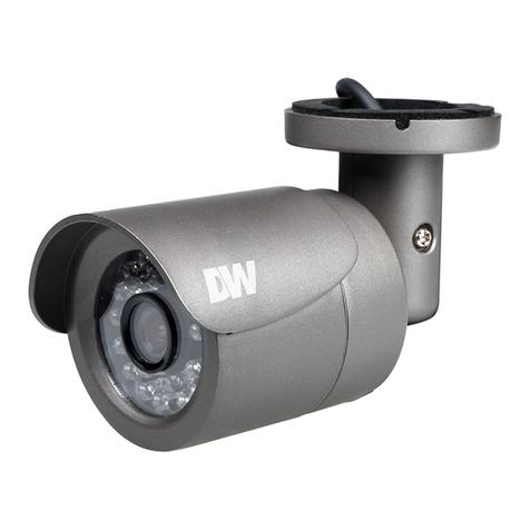
Megapix DWC-MB45DIA User manual

User’s Manual7FS
#FGPSFJOTUBMMJOHBOEVTJOHUIFDBNFSBQMFBTFSFBEUIJTNBOVBMDBSFGVMMZ
#FTVSFUPLFFQJUIBOEZGPSGVUVSFSFGFSFODF
.&("QJY¥.FHBQJYFM*OEPPS
0VUEPPS#VMMFU$BNFSB
%8$.#5DJ"

4BGFUZ*OGPSNBUJPO
5IJTTZNCPMJOEJDBUFTUIBUEBOHFSPVTWPMUBHF
DPOTJTUJOHBSJTLPGFMFDUSJDTIPDLJTQSFTFOUXJUIJO
UIJTVOJU
8BSOJOH 1SFDBVUJPO
5IJTFYDMBNBUJPOQPJOUTZNCPMJTJOUFOEFEUPBMFSUUIF
VTFSUPUIFQSFTFODFPGJNQPSUBOUPQFSBUJOHBOE
NBJOUFOBODFTFSWJDJOHJOTUSVDUJPOTJOUIFMJUFSBUVSF
BDDPNQBOZJOHUIFBQQMJBODF
503&%6$&5)&3*4,0'&-&$53*$4)0$,%0/053&.07&$07&303#"$,/064&34&37*$&"#-&
1"354*/4*%&3&'&34&37*$*/(5026"-*'*&%4&37*$&1&340//&-
$"65*0/
$"65*0/
3*4,0'&-&$53*$4)0$,
%0/0501&/
5PQSFWFOUEBNBHFXIJDINBZSFTVMUJOGJSFPSFMFDUSJDTIPD
IB[BSEEPOPUFYQPTFUIJTBQQMJBODFUPSBJOPSNPJTUVSF
8"3/*/(
#FTVSFUPVTFPOMZUIFTUBOEBSEBEBQUFSUIBUJTTQFDJGJFEJ
UIFTQFDJGJDBUJPOTIFFU6TJOHBOZPUIFSBEBQUFSDPVMEDBVT
GJSFFMFDUSJDBMTIPDLPSEBNBHFUPUIFQSPEVDU
*ODPSSFDUMZDPOOFDUJOHUIFQPXFSTVQQMZPSSFQMBDJOHCBUUFSZ
NBZDBVTFFYQMPTJPOGJSFFMFDUSJDTIPDLPSEBNBHFUPUI
QSPEVDU
%POPUDPOOFDUNVMUJQMFDBNFSBTUPBTJOHMFBEBQUFS
&YDFFEJOHUIFDBQBDJUZNBZDBVTFFYDFTTJWFIFBUHFOFSBUJPO
PSGJSF
4FDVSFMZQMVHUIFQPXFSDPSEJOUPUIFQPXFSSFDFQUBDMF
*OTFDVSFDPOOFDUJPONBZDBVTFGJSF
8IFOJOTUBMMJOHUIFDBNFSBGBTUFOJUTFDVSFMZBOEGJSNMZ
"GBMMJOHDBNFSBNBZDBVTFQFSTPOBMJOKVSZ
%POPUQMBDFDPOEVDUJWFPCKFDUTFHTDSFXESJWFSTDPJOT
NFUBMJUFNTFUDPSDPOUBJOFSTGJMMFEXJUIXBUFSPOUPQP
UIFDBNFSB%PJOHTPNBZDBVTFQFSTPOBMJOKVSZEVFUPGJSF
FMFDUSJDTIPDLPSGBMMJOHPCKFDUT
%POPUJOTUBMMUIFVOJUJOIVNJEEVTUZPSTPPUZMPDBUJPOT
%PJOHTPNBZDBVTFGJSFPSFMFDUSJDTIPDL
*GBOZVOVTVBMTNFMMTPSTNPLFDPNFGSPNUIFVOJUTUPQ
VTJOHUIFQSPEVDU*NNFEJBUFMZEJTDPOOFDUUIFQPXFSTPSDF
BOEDPOUBDUUIFTFSWJDFDFOUFS$POUJOVFEVTFJOTVDIB
DPOEJUJPONBZDBVTFGJSFPSFMFDUSJDTIPDL
*GUIJTQSPEVDUGBJMTUPPQFSBUFOPSNBMMZDPOUBDUUIFOFBSFTU
TFSWJDFDFOUFS/FWFSEJTBTTFNCMFPSNPEJGZUIJTQSPEVDUJO
BOZXBZ
8IFODMFBOJOHEPOPUTQSBZXBUFSEJSFDUMZPOUPQBSUTPGUIF
QSPEVDU%PJOHTPNBZDBVTFGJSFPSFMFDUSJDTIPDL
8"3/*/(
1.
2.
3.
4.
5.
6.
7.
8.
9.
10.
1SFDBVUJPO
0QFSBUJOH
t#FGPSFVTJOHNBLFTVSFQPXFSTVQQMZBOEBMMPUIFSQBSUTBSF
QSPQFSMZDPOOFDUFE
t8IJMFPQFSBUJOHJGBOZBCOPSNBMDPOEJUJPOPSNBMGVODUJPO
JTPCTFSWFETUPQVTJOHUIFDBNFSBJNNFEJBUFMZBOEDPOUBDU
ZPVSEFBMFS
)BOEMJOH
t%POPUEJTBTTFNCMFPSUBNQFSXJUIQBSUTJOTJEFUIFDBNFSB
t%POPUESPQUIFDBNFSBPSTVCKFDUJUUPTIPDLPSWJCSBUJPOBT
UIJTDBOEBNBHFUIFDBNFSB
t$MFBOUIFDMFBSEPNFDPWFSXJUIFYUSBDBSF4DSBUDIFTBOE
EVTUDBOSVJOUIFRVBMJUZPGUIFDBNFSBJNBHF
*OTUBMMBUJPOBOE4UPSBHF
t%POPUJOTUBMMUIFDBNFSBJOBSFBTPGFYUSFNFUFNQFSBUVSF
FYDFFEJOHUIFBMMPXFESBOHF
t"WPJEJOTUBMMJOHJOIVNJEPSEVTUZFOWJSPONFOUT
t"WPJEJOTUBMMJOHJOQMBDFTXIFSFSBEJBUJPOJTQSFTFOU
t"WPJEJOTUBMMJOHJOQMBDFTXIFSFUIFSFBSFTUSPOHNBHOFUJD
ãFMETBOEFMFDUSJDTJHOBMT
t"WPJEJOTUBMMJOHJOQMBDFTXIFSFUIFDBNFSBXPVMECFTVCKFDU
UPTUSPOHWJCSBUJPOT
t/FWFSFYQPTFUIFDBNFSBUPSBJOPSXBUFS

*NQPSUBOU4BGFUZ*OTUSVDUJPOT
%JTQPTBMPG0ME"QQMJBODFT
8IFOUIJTDSPTTFEPVUXIFFMCJOTZNCPMJTBUUBDIFEUPBQSPEVDUJUNFBOTUIFQSPEVDUJTDPWFSFECZUIF
&VSPQFBO%JSFDUJWF&$
"MMFMFDUSJDBMBOEFMFDUSPOJDQSPEVDUTTIPVMECFEJTQPTFEPGTFQBSBUFMZGPSNUIFNVOJDJQBMXBTUFTUSFBN
TUSFBNJOBDDPSEBODFUPMBXTEFTJHOBUFECZUIFHPWFSONFOUPSUIFMPDBMBVUIPSJUJFT
5IFDPSSFDUEJTQPTBMPGZPVSPMEBQQMJBODFXJMMIFMQQSFWFOUQPUFOUJBMOFHBUJWFDPOTFRVFODFTGPSUIF
FOWJSPONFOUBOEIVNBOIFBMUI
'PSNPSFEFUBJMFEJOGPSNBUJPOBCPVUEJTQPTBMPGZPVSPMEBQQMJBODFQMFBTFDPOUBDUZPVSDJUZPGGJDF
XBTUFEJTQPTBMTFSWJDFPSUIFTIPQXIFSFZPVQVSDIBTFEUIFQSPEVDU
5IJTFRVJQNFOUIBTCFFOUFTUFEBOEGPVOEUPDPNQMZXJUIUIFMJNJUTGPSB$MBTT"EJHJUBMEFWJDFQVSTVBOUUPQBSUPGUIF'$$3VMFT
5IFTFMJNJUTBSFEFTJHOFEUPQSPWJEFSFBTPOBCMFQSPUFDUJPOBHBJOTUIBSNGVMJOUFSGFSFODFXIFOUIFFRVJQNFOUJTPQFSBUFEJOBDPNNFSDJBMFOWJSPONFOU
5IJTFRVJQNFOUHFOFSBUFTVTFTBOEDBOSBEJBUFSBEJPGSFRVFODZFOFSHZBOEJGOPUJOTUBMMFEBOEVTFEJOBDDPSEBODFXJUIUIFJOTUSVDUJPONBOVBMNBZDBVTF
IBSNGVMJOUFSGFSFODFUPSBEJPDPNNVOJDBUJPOT0QFSBUJPOPGUIJTFRVJQNFOUJOBSFTJEFOUJBMBSFBJTMJLFMZUPDBVTFIBSNGVMJOUFSGFSFODFJOXIJDIDBTFUIFVTFS
XJMMCFSFRVJSFEUPDPSSFDUUIFJOUFSGFSFOFDFBUIJTPXOFYQFOTF
3FBEUIFTFJOTUSVDUJPOT"MMTBGFUZBOEPQFSBUJOHJOTUSVDUJPOTTIPVMECFSFBECFGPSFJOTUBMMBUJPOPSPQFSBUJPO
,FFQUIFTFJOTUSVDUJPOT5IFTBGFUZPQFSBUJOHBOEVTFJOTUSVDUJPOTTIPVMECFSFUBJOFEGPSGVUVSFSFGFSFODF
)FFEBMMXBSOJOHT"MMXBSOJOHTPOUIFQSPEVDUBOEJOUIFPQFSBUJOHJOTUSVDUJPOTTIPVMECFBEIFSFEUP
'PMMPXBMMJOTUSVDUJPOT"MMPQFSBUJOHBOEVTFJOTUSVDUJPOTTIPVMECFGPMMPXFE
%POPUVTFUIJTEFWJDFOFBSXBUFS'PSFYBNQMFOFBSBCBUIUVCXBTICPXMLJUDIFOTJOLMBVOESZUVCJOBXFU
CBTFNFOUOFBSBTXJNNJOHQPPMFUD
$MFBOPOMZXJUIESZDMPUI6OQMVHUIJTQSPEVDUGSPNUIFXBMMPVUMFUCFGPSFDMFBOJOH%POPUVTFMJRVJEDMFBOFST
%POPUCMPDLBOZWFOUJMBUJPOPQFOJOHT*OTUBMMJOBDDPSEBODFXJUIUIFNBOVGBDUVSFSTJOTUSVDUJPOT4MPUTBOE
PQFOJOHTJOUIFDBCJOFUBSFQSPWJEFEGPSWFOUJMBUJPOUPFOTVSFSFMJBCMFPQFSBUJPOPGUIFQSPEVDUBOEUPQSPUFDUJU
GSPNPWFSIFBUJOH5IFPQFOJOHTTIPVMEOFWFSCFCMPDLFECZQMBDJOHUIFQSPEVDUPOCFETPGBSVHPSPUIFSTJNJMBS
TVSGBDFT5IJTQSPEVDUTIPVMEOPUCFQMBDFEJOBCVJMUJOJOTUBMMBUJPOTVDIBTBCPPLDBTFPSSBDLVOMFTTQSPQFS
WFOUJMBUJPOJTQSPWJEFEBOEUIFNBOVGBDUVSFSTJOTUSVDUJPOTIBWFCFFOBEIFSFUP
%POPUJOTUBMMOFBSBOZIFBUTPVSDFTTVDIBTSBEJBUPSTIFBUSFHJTUFSTPSPUIFSBQQBSBUVTJODMVEJOHBNQMJGJFST
UIBUQSPEVDFIFBU
%POPUEFGFBUUIFTBGFUZQVSQPTFPGUIFQPMBSJ[FEPSHSPVOEJOHUZQFQMVH"QPMBSJ[FEQMVHIBTUXPCMBEFTXJUI
POFXJEFSUIBOUIFPUIFS"HSPVOEJOHUZQFQMVHIBTUXPCMBEFTBOEBUIJSEHSPVOEJOHQSPOH5IFXJEFCMBEF
PSUIFUIJSEQSPOHBSFQSPWJEFEGPSZPVSTBGFUZ*GUIFQSPWJEFEQMVHEPFTOPUGJUJOUPZPVSPVUMFUDPOTVMUBO
FMFDUSJDJBOGPSSFQMBDFNFOU
1SPUFDUUIFQPXFSDPSEGSPNCFJOHXBMLFEPOPSQJODIFEQBSUJDVMBSMZBUQMVHTDPOWFOJFODFSFDFQUBDMFTBOE
UIFQPJOUXIFSFUIFZFYJUGSPNUIFBQQBSBUVT
0OMZVTFBUUBDINFOUTBDDFTTPSJFTTQFDJGJFECZUIFNBOVGBDUVSFS
6TFPOMZXJUIDBSUTUBOEUSJQPECSBDLFUPSUBCMFTQFDJGJFECZUIFNBOVGBDUVSFS
PSTPMEXJUIUIFBQQBSBUVT8IFOBDBSUJTVTFEVTFDBVUJPOXIFONPWJOHUIFDBSUBQQBSBUVT
DPNCJOBUJPOUPBWPJEJOKVSZGSPNUJQPWFS
6OQMVHUIFBQQBSBUVTEVSJOHMJHIUOJOHTUPSNTPSXIFOVOVTFEGPSMPOHQFSJPETPGUJNF
3FGFSBMMTFSWJDJOHUPRVBMJGJFETFSWJDFQFSTPOOFM4FSWJDJOHJTSFRVJSFEXIFOUIFBQQBSBUVTIBTCFFOEBNBHFE
JOBOZXBZTVDIBTQPXFSTVQQMZDPSEPSQMVHJTEBNBHFEMJRVJEIBTCFFOTQJMMFEPSPCKFDUTIBWFGBMMFOJOUPUIF
BQQBSBUVTUIFBQQBSBUVTIBTCFFOFYQPTFEUPSBJOPSNPJTUVSFEPFTOPUPQFSBUFOPSNBMMZPSIBTCFFO
ESPQQFE

5BCMFPG$POUFOUT
*OUSPEVDUJPO
1SPEVDU"DDFTTPSJFT
1BSUT/BNF
*OTUBMMBUJPO
'BDUPSZ3FTFU
*OTUBMMBUJPO
$BCMJOH
.FNPSZ4%$BSE
/FUXPSL4FUVQ
%8*1'JOEFS
/FUXPSL$POOFDUJPO0QUJPOT
%%/43FHJTUSBUJPO
/FUXPSL&OWJSPONFOUT
1PSU'PSXBSEJOH
4UBSUJOHUIF*1$BNFSB
8FC7JFXFS
(6*0WFSWJFX
$BNFSB4FUUJOHT
4FUVQ4UBUVT
4FUVQ/FUXPSL
4FUVQ7JEFP4PVSDF
4FUVQ$BNFSB4FUVQ
4FUVQ.PUJPO%FUFDU
4FUVQ30*&ODPEJOH
4FUVQ04%
4FUVQ7JEFP1SPGJMF
4FUVQ"VEJP1SPGJMF
4FUVQ4USFBNJOH4FUUJOH
4FUVQ&WFOUT
4FUVQ-PDBM4UPSBHF
4FUVQ%BUF5JNF
4FUVQ61O1
4FUVQ#POKPVS
4FUVQ4ZTMPHE
4FUVQ4/.1
4FUVQ1PSU
4FUVQ4FDVSJUZ
4FUVQ%%/4
4FUVQ"DDPVOU
4FUVQ'JSNXBSF6QEBUF
4FUVQ'BDUPSZ%FGBVMU
4FUVQ3FQPSU
4FUVQ0QFO4PVSDF*OGP
4FUVQ3FCPPU
4FUVQ-PHPVU
%JNFOTJPOT
8BSSBOUZ
-JNJUT&YDMVTJPOT

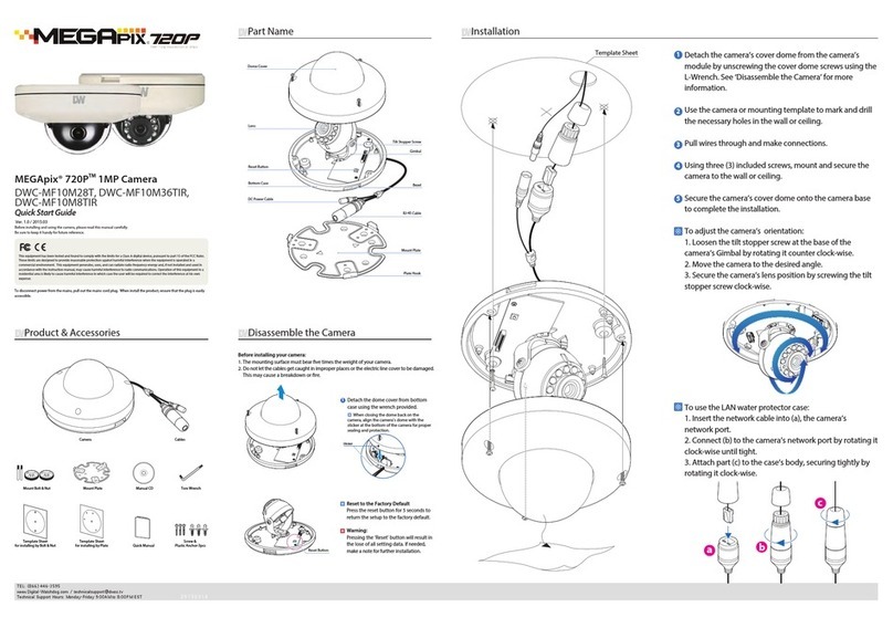
Product & Accessories
Introduction -
Camera
Cables
Screw & Plastic Anchor-4pcs
Test Monitor Cable Quick ManualTemplate Sheet
Please check if all the camera and accessories are included in the package.
Torx Wrench
Manual CD Waterproof cap & Gasket
5

Part Name
Introduction -
Bracket
Pan/Tilt Stoper Screw
Lens
Control Board
Con Cap
Sunshield
6

Installation
Installation -
Before installing your camera, you have to read the following cautions.
1. You have to check whether the location can bear ve times of the weight of your camera.
2. Don’t let the cable to be caught in improper place or the electric line cover to be damaged. Otherwise
it may cause a breakdown or re.
3. When installing your camera, don’t allow any person to approach the installation site. If you have any
valuable things under the place, move them away.
Zoom Out
Zoom In
WIDE
TELE
Reset to the Factory Default
Press the reset button for 5 seconds to return the setup
to the factory default.
Warning
If you press the ‘Reset’ button, you will lose all setting
data. If needed, please, make a note for further
installation.
1
2
3
4
To pass cables through the wall/ceiling, drill holes on
the wall/ceiling.
Connect the network cable, power cable respectively.
See the section ‘Installation - Cabling’ for details.
Fix the camera on the wall/ceiling by screw provided.
Loosen the Pan/Tilt stoper screw a litte before xing the camera.
By using the video test cable, check the screen during
installation. You can adjust the zoom ratio using the
T-W jog button.
SD Card Slot
Reset
T-W Jog Button
Test Video Output
7

Cabling
Installation -
Power
Two Options
Use a PoE-enabled switch to connect data and power through a single cable and begin viewing and recording images instantly.
A non-PoE switch will require an adaptor for power transmission.
Ethernet cableEthernet cable
2. Using a Non-PoE Switch
If a PoE-enabled switch is not used, use a power adaptor
for power transmission and non-PoE switch for data
transmission.
Follow the illustrations below to connect the camera
without a PoE-enabled Switch.
1. Using a PoE-Enabled Switch
The Camera is PoE-compliant, allowing transmission of
power and data via a single Ethernet cable.
PoE eliminates the need for the dierent cables used to
power, record, or control the camera. Follow the illustration
below to connect the camera to a PoE-enabled switch using
an Ethernet cable.
8

N.C
Activation
Activation
N.O ,Q
&20
,Q
&20
,Q
&20
,Q
&20
Cabling
Installation -
1
4Alarm In
1Audio In 2Audio Out
3
4
2
Red : ALARM_OUT+
Black : ALARM_OUT-
Yellow : GND
White : ALARM_IN+
Alarm Out
It connects to the alarm lights, siren or lamps and the sensor
types are normal open and normal close.
Alarm & light bar + need to be connected with
power + or adaptor +.
Alarm out+ need to be connected with Alarm - or light bar -.
Alarm out- need to be connected with power - or adaptor -.
Alarm In
Cable of the sensor/alarm input device should connect to
white and yellow line of the Alam cable.
Audio In
Cable of the sensor/alarm input device should connect to
alarm in+ and alarm in- of the cable slot.
Audio Out
It connects to the alarm lights, siren or lamps and the sensor
types are normal open and normal close.
Cable of the alarm output device should connect to alarm
out+ and alarm out- of the cable slot.
3Alarm Out
If the speaker without the amplier is connected to Audio Out port, it
Out port, it doesn’t work properly. Therefore, the speaker with the
amplier or the separate amplier is needed.
9

Inserting/Removing SD Memory Card
Installation -
1Inserting an SD Memory Card
Insert the SD card in the arrow direction.
Don’t insert the SD memory card while it’s upside down by force.
Otherwise, it may damage the SD memory card.
Use the tweezers when inserting or picking out the SD card.
2Removing an SD Memory Card
Removing an SD Memory Card Gently press down on the
exposed end of the memory card as shown in the diagram
to eject the memory card from the slot.
Pressing too hard on the SD memory card can cause the card to
shoot out uncontrollably from the slot when released.
If you have saved data in the SD memory card, removing the SD
memory card prior to setting record to OFF will cause damage to
the data stored in the card.
Micro
The memory card is an external data storage device
that has
to record and share video, audio, and text data using
digital devices.
Recommended SD Card Specication (Not Included)
- Type: Micro SD (SD/SDHC/SDXC)
- Manufacturer: Transcend, Kingston, Toshiba, SanDisk
- Capacity: 4GB~128GB
- Class: over UHS-I U3 Class 10
10

/FUXPSL4FUVQ
%8*1'JOEFS
5PTBWFUIFDIBOHFTNBEFUPUIFDBNFSBhTTFUUJOHTJOQVU*%BOE
18PGUIFDBNFSBGPSBVUIFOUJDBUJPO
*GUIFDBNFSBOFFETUPCFSFCPPUFEBGUFSUIFTFUUJOHTXFSFDIBOHFE
QSFTTUIFh3FCPPUhCVUUPO5IFDBNFSBXJMMQPXFSDZDMFBOEXJMM
BQQFBSCBDLJOUIFTFBSDISFTVMUTPODFUIFSFCPPUJTDPNQMFUF
$MJDLA4BWFUPTBWFDIBOHFEWBMVFT
5PVQEBUFUIFDBNFSBhTGJSNXBSFGSPNUIF%8*1'JOEFS
DMJDLPOUIFGJSNXBSFUBCVQMPBEUIFGJSNXBSFGJMFBOE
TFMFDUUIFDBNFSBTUPVQEBUF:PVDBOVQEBUFNVMUJQMF
DBNFSBTBUUIFTBNFUJNF
(PUPIUUQXXXEJHJUBMXBUDIEPHDPNBOETFBSDIGPSA*1
'JOEFSPOUIFRVJDLTFBSDICBSBUUIFUPQPGUIFQBHF
5IFMBUFTU*1'JOEFSTPGUXBSFXJMMBQQFBSJOUIFTFBSDI
SFTVMUT$MJDLPOUIFMJOLUPEPXOMPBEUIFGJMFUPZPVS
DPNQVUFS
5IFTPGUXBSFXJMMTDBOZPVSOFUXPSLGPSBMMTVQQPSUFE
DBNFSBTBOEEJTQMBZUIFSFTVMUTJOUIFUBCMF"MMPXVQUP
TFDPOETGPSUIF*1*OTUBMMFSUPGJOEUIFDBNFSBPOUIF
OFUXPSL
ZPVDBOQSFTTUIFh3FGSFTI-JTUhUPTFBSDIUIFOFUXPSL
BHBJOPSGJMUFSUIFTFBSDISFTVMUTCZFOUFSJOHBWBMVFJOUIF
GJMUFSCPYBUUIFCPUUPNPGUIFQBHF
$IFDLUIFCPYOFYUUPh%JTQMBZ$BNFSB5IVNCOBJMhUPWJFX
B+1&(JNBHFPGUIFDBNFSBhTWJFXOFYUUPUIFDBNFSB
OBNFPOTVQQPSUFENPEFMT
4FMFDUBDBNFSBGSPNUIFMJTUCZEPVCMFDMJDLJOHPOJU5IF
DBNFSBhTOFUXPSLJOGPSNBUJPOXJMMBQQFBS*GOFDFTTBSZZPV
DBOBEKVTUUIFDBNFSBTOFUXPSLUZQF
5IFDBNFSBhTEFGBVMUOFUXPSLJOGPSNBUJPOJT
4FMFDU%)$1JGUIFJOUFSOFUTFSWJDFJTEZOBNJD*15IJTXJMMBMMPXUIF
DBNFSBUPSFDFJWFJUT*1BEESFTTGSPNUIF%)$1TFSWFS
4FMFDU45"5*$UPNBOVBMMZFOUFSUIFDBNFSBT*1BEESFTTTVCOFU
NBTL(BUFXBZBOE%/4JOGPSNBUJPO
$POUBDUZPVSOFUXPSLBENJOJTUSBUPSGPSNPSFJOGPSNBUJPO
%FGBVMU5$1*1JOGPSNBUJPO
*1
4VCOFU.BTL
(BUFXBZ
%/4
5PWJFXUIFDBNFSBhTXFCDMJFOUDMJDLPOh7JFX$BNFSB8FCTJUFh
"A1PSU'PSXBSEJOHIBTUPCFTFUJOZPVSOFUXPSLTSPVUFSGPS
FYUFSOBMBDDFTTUPUIFDBNFSB
%FGBVMU*%18BENJOBENJO

Quick Start of Network Connection
Network Setup -
Please follow the steps below to complete
the initial setup of the network function.
1.
Open the IP Installer on a PC, then search for the IP camera.
If multiple numbers of camera are connected it should be
distinguished by the mac address of the Camera.
Click the Camera IP, and connect to the WEB PAGE.
2.
3.
4.
Default ID/Password to access IP Camera are both the
word: admin.
5.
Familiarize yourself with the Viewer Interface Screen.6.
please install VLC to display live video.7.
The IP setting can be set to ‘STATIC’ at IP Installer or web
viewer followed by Setup -> Network -> Network Settings.
8.
If you have a DHCP server, it will automatically set the Camera IP.
If you do not have a DHCP server, Camera IP is set to 192.168.1.80
after one minute. In this case, PC IP must be changed to the IP to
be able to access the 192.168.1.80.
Please do not power on the IP Camera until instructed.
Explorer.
If connecting the IP Camera directly to a modem, power down
and reset the modem. Leave the modem powered down until
con tions ar nalized with the IP Camera and the IP Camera
has been correctly connected to the modem.
If the IP Camera is connected to a network which utilizes a
router, you must have Port Forwarding co ured on your
personal router to forward all ports to the IP address you
have assigned the IP Camera.
(if necessary), you may access your IP Camera on your local
network by opening Internet Explorer and specifying the IP
address and Web Port that you have assigned to the IP
Camera.
9.
10.
Example: http://192.168.0.200:8888
If you leave your Web Port set to 80, you don’t need to specify
the port in the Address Bar to access to your IP Camera.
Access your IP Camera via the Internet :
If you use a static IP address assigned by your ISP
1) Open Internet Explorer.
2) Type the IP of the IP Camera.
3) If you use a router, type the routers’ static IP and the web port
number of the IP Camera.
If you have a dynamic address provided by your ISP
1) Open Internet Explorer and visit the DDNS website.
2) Register the IP Camera.
3) Reboot the IP Camera.
4) Give the DDNS server 10 minutes to locate your IP Camera’s
IP information.
5) Click the refresh button in the Internet Explore.
6) After your camera is connected, select your camera.
11.

DDNS Registration
Network Setup -
If you have DYNAMIC IP service from your
Internet Service Provider (ISP), you can’t tell
the current IP address of the IP Camera.
To solve this problem, you have to register to
our DDNS service.
At, you have to check if you are using
dynamic addressing. If so, register your IP
Video Server on our DDNS website before you
cre, setup, or install the IP Camera.
Even though your IP is not dynamic, you will
just remember ‘hostname.dyndns.com/gate1’
instead of complicated series of numbers like
http://201.23.4.76:8078.
For more details, contact our Support Center.
To use a public DDNS called ‘dyndns’ or ‘no-ip’, refer to the detail
information on how to use the service.
(Visit the web site : http://www.dyndns.com or
http://www.no-ip.com)

Guide to Network Environment
Network Setup -
Please congure the IP Camera at the
installation site. You must determine your
network scenario in order to congure the IP
Camera with the proper TCP/IP settings.
This tutorial will guide you through the
process. Before actually conguring the IP
Camera, determine settings to be applied.
Record those settings to be used to congure
your IP Camera for reference.
When conguring your IP Camera, treat the
IP Camera as another PC on your network.
You will assign it several addresses and other
TCP/IP properties to match your current
network.
This step-by-step tutorial will teach what IP
addresses and network congurations should
be assigned based on the network scenario.
If you were not given any IP addresses or the ISP was responsible
for the setup and installation of your Internet connection, go to
step 2.
If you are not using a router on your network, your ‘Current TCP/IP
Settings’(from the previous section) and ‘Assigned IP Addresses
from My ISP’ will be exactly the same.
Before you begin, locate any information and settings
received from your Internet Service Provider (ISP). You may
need to refer to these IP addresses at a later time during the
conguration.
1.
You must determine whether the IP address is STATIC or
DYNAMIC. At this moment, you are only concerned about the
ISP. Did they provide you with a STATIC or DYNAMIC address?
If you are unsure, contact your ISP.
Congure your IP Camera’s TCP/IP settings for network
connectivity by selecting Setup from the main interface and
selecting TCP/IP located on the left of the Setup screen.
If prompted for ID and Password, use ‘admin’ for both entries.
The default web port number is 80. If port 80 is blocked by
the ISP, a value between 1025 ~ 60000 should be used. If TCP
port 80 is blocked, consult the ISP
2.
3.
4.
Current TCP/IP Settings
IP Address
Subnet Mask
Default Gateway
Primary DNS Server
Secondary DNS Server (Option)
Static Dynamic
5. The following descriptions are several basic network
scenarios. Determine which scenario describes your network.
If your network does not match one of the scenarios below
and you are unsure how to setup your IP Camera, contact
your network administrator and then call our Support Center.
You cannot control the rectangular gray areas and only the ISP
has access to the devices.

Setup Case A, B
Network Setup -
Case A:
Dynamic IP +
Personal Router [Most SOHO]
Personal Router
W/Intergrated Switch
Cable/xDSL Modem
(ISP Provided)
Phone Line
or CATV
PC
Internet
Case B:
Static(Fixed) IP +
PC
Personal Router
W/Intergrated Switch
Gateway or Router
at ISP
Public Line
Internet
as follows :
STATIC (even though you have Dynamic IP from
your ISP, use STATIC on the IP Camera)
Network Type :1.
A private IP address such as
192.168.0.200 (Example)
Internet Address :2.
You need to assign an IP address to the IP Camera just as you do
with PC.
The IP address you assign must be unique to your network and
match your network as well. For information on how to choose
a unique IP and match your network, read the FAQ.
The IP address you assign must be a private IP. For information
on how to choose a private IP please, read the FAQ.
255.255.255.0 (Example)
192.168.0.1 (Example)
Subnet Mask :3.
You must use the same subnet mask as the one you noted under
‘Current TCP/IP Settings’.
Default Gateway :4.
This IP address must be the IP address of your router.
(private or LAN side)
Use the same Default Gateway you noted under ‘Current TCP/IP
Settings’.
Use the 1st DNS Server from ‘Assigned IP
Address from My ISP’.
Preferred DNS Server :5.
Use the DDNS server.
DDNS Server :6.
This is the same site you will register later to accommodate
dynamic IP from your ISP.
8888Web Port :7.
Do not use the default port 80 as this number must be changed.
You may select any number between 1025 ~ 60000.
If you did not receive any IP addresses from your ISP, contact
the ISP and acquire the IP address of their DNS server.
Camera
Camera

Setup Case C, D
Network Setup -
To connect the IP Camera directly to a modem, power down
and reset the modem. Leave the modem powered down until
Camera has been connected correctly to the modem. Then
power on the modem, followed by the IP Camera.
Cable/xDSL Modem
(ISP Provided)
Phone Line
or CATV
Internet
Internet
Public Line Gateway or
Router at ISP
STATICNetwork Type :1.
A static IP address received from your ISP such
as 24.107.88.125 (Example)
Internet Address :2.
You need to assign an IP address to the IP Camera just as you do
with PC.
Subnet mask assigned from your ISP such as
255.255.255.240 (Example)
24.107.88.113 (Example)
Subnet Mask :3.
Default Gateway :4.
Use the assigned default gateway from your ISP
Use the 1st DNS Server from ‘Assigned IP
Address from My ISP’
Preferred DNS Server :5.
Use the DDNS server
DDNS Server :6.
This is the same site you will register later to utilize our DDNS
service.
80Web Port :7.
You may select any number between 1025 ~ 60000.
If you have not received any IP addresses from your ISP, contact
them to acquire the IP address of their DNS server.
DYNAMICNetwork Type :1.
Use the DDNS serverDDNS Server :2.
This is the same site you will register later to accommodate
dynamic IP from your ISP.
80Web Port :3.
You may select any number between 1025 ~ 60000.
as follows :
as follows :
Case C:
Static(Fixed) IP [Dedicated line directly
to the IP Camera]
Case D:
Dynamic IP + DSL/Cable Modem [Connected
directly to the IP Camera]
Camera
Camera

Port Forwarding
Network Setup -
After entering the correct TCP/IP settings, you
are ready for ‘Port Forwarding’(Cases A, B).
Please record the TCP/IP settings of your IP Camera for future
reference. You may need this information to access your IP
1.
After clicking ‘Apply’, the system will prompt for a reboot.
Please allow the system 50 seconds to reboot and accept the
changes. After 50 seconds, close the con ration screen.
The view will display‘Trying to Reconnect’. If the ACTIVE light
, the IP Camera has rebooted. After the system
reboots completely, remove the power supply from the
unit and close Internet Explorer.
Return your PC/Laptop TCP/IP properties to their original
settings.
Before installing the IP Camera, you must use‘Port
Forwarding’ on your personal router (Cases A, B).
You will need to forward 1 ports:
t Web Port
All the ports will be forwarded to the IP address you
assigned to the IP Camera.
In the example above, you would forward:
t
2.
3.
4.
IP Camera TCP/IP Settings
IP Address
Subnet Mask
Default Gateway
Preferred DNS Server
DDNS Server
Web Port
For information on how to use ‘Port Forwarding’, please read
Appendix C.

Starting IP Camera
Network Setup -
After forwarding correctly the Web Port,
through your router (if applicable), install the
IP Camera in a proper location.
Locate the serial number located on the label attached to the
bottom of the IP Camera, you will need this for DDNS
registration.
Connect the IP Camera to your router or cable/DSL modem
(per your network scenario) via a Cat5/5e UTP Ethernet
network cable.
Supply power to the IP Camera.
After 1 minute, verify the IP Camera indicators:
t-*/,Flickering/Solid
(if necessary), access your IP Camera on your local network
by opening Internet Explorer and specifying the IP address
and Web Port assigned to the IP Camera.
1.
2.
3.
4.
5.
Access your IP Camera via the Internet :6.
Examples: http://192.168.0.200:8888 or http://24.106.88.123
If you left your Web Port set to 80, do not need to specify the
port in the Address Bar to access the IP Camera.
If you use Case B, C
1) Open Internet Explorer.
2) Type the IP of the IP Camera.
If you use Case A, D
1) Open Internet Explorer.
2) Visit the DDNS website.
3) Register the IP Camera.
4) Give the DDNS server 10 minutes (MAX) to locate your IP
Camera’s IP information. You may reboot the server to send an
immediate request to our DDNS server.
5) After your camera is connected, select your camera.
The di ence between B and C is that B needs to set the port
forwarding.
Since the type of DDNS s from the service type, refer to
the related service site.

Web Viewer Screen-
Camera Web Server
- The web server of a camera consists of two parts. The parts are Web Monitoring Page and Web Setting Page.
- Internet Explorer version 8.0 or higher are recommended as the Internet browser to be used.
- Type the IP address that is assigned to a camera on the address window of a web browser and press“Enter”.
(The default IP address is 192.168.1.2.)
- Checkpoints before access
1) The range of the camera IP address should be same as the range of IP address of the monitoring PC.
2) The camera IP address should be unique on the local network that are connected to the monitoring PC.
Administrator connection (on the initial page)
[ID] root (Unchangeable)
[Password] pass (the default password, it can be changed on the web setting page)
- Type the ID and password and click the button “Login’, the web monitoring page shows up.
(Type the ID and password and click the button“Login after checking the box “Setting”’, the web setting page
shows up.)
Guest connection (on the initial page)
[Guest Login] click the text“Guest Login” below the button “Login” without an ID and a password.
- On the guest connection, it is available to use only the functions that are allowed restrictively on the web
monitoring page and it is not allowed to access to the web setting page.
ڼThe initial page of the web server

ڼWeb monitoring page 1 (Guest connection)
ڼWeb monitoring page 2 (Administrator connection)
NOTE: All information provided in the following pages display options available to the administrator user.
Table of contents
Other Megapix Security Camera manuals
Popular Security Camera manuals by other brands
VADDIO
VADDIO RoboSHOT 12 Series Complete manual
Eneo
Eneo HDD-2080Z03IR D Quick installation guide

Swann
Swann MicroCam HD Security Camera instruction manual
American Dynamics
American Dynamics SpeedDome Ultra VII RAS917LS Configuration
Axis
Axis M2025-LE user manual
Concept Pro
Concept Pro AHD Series user manual
