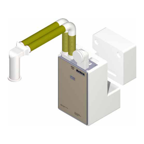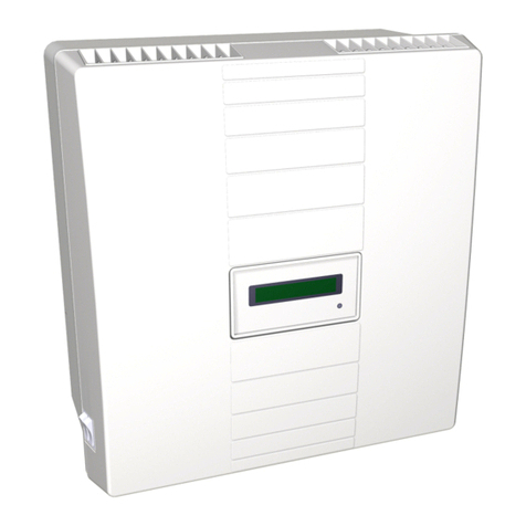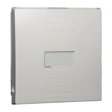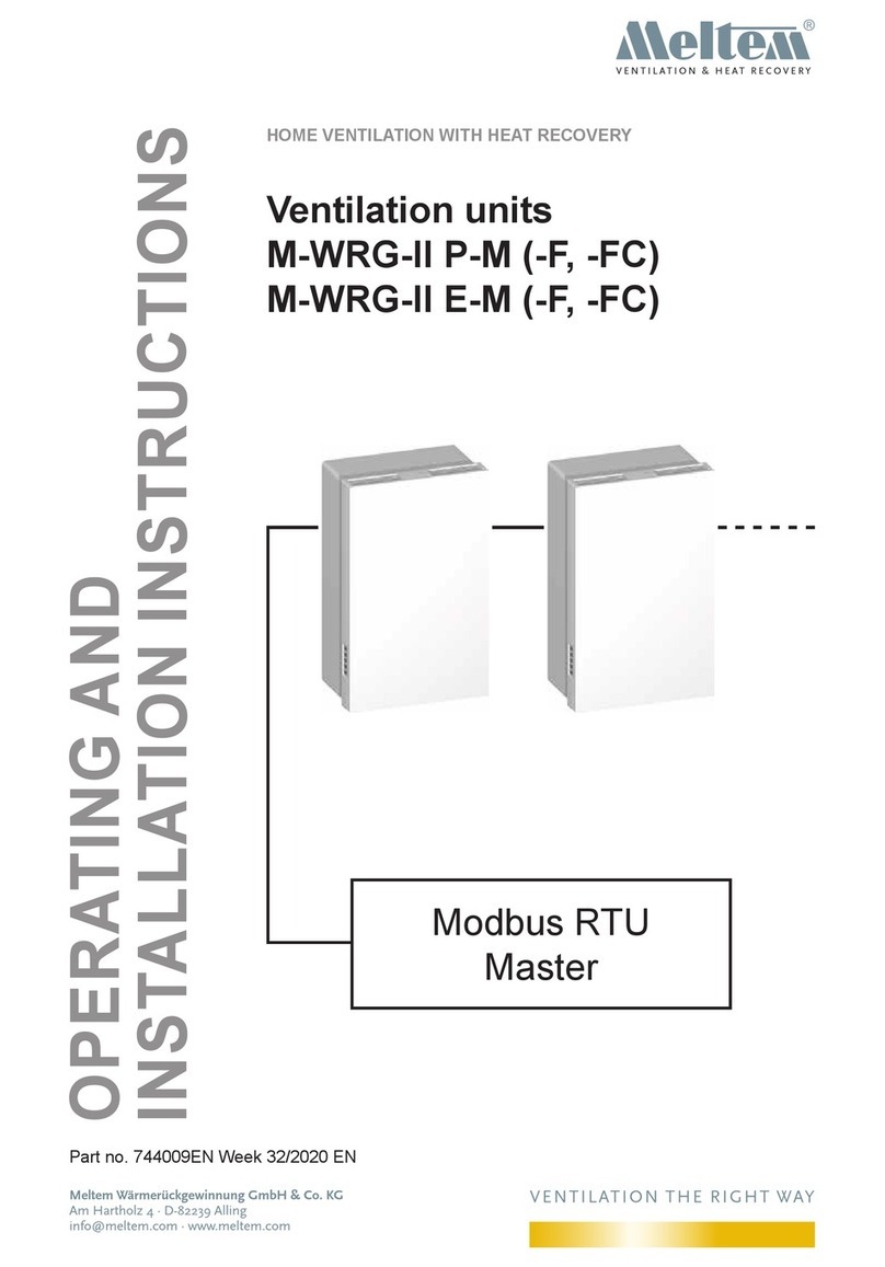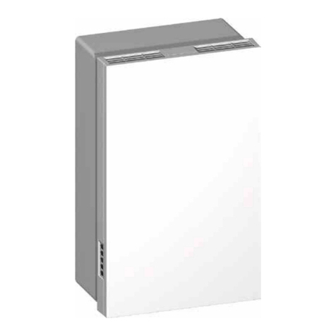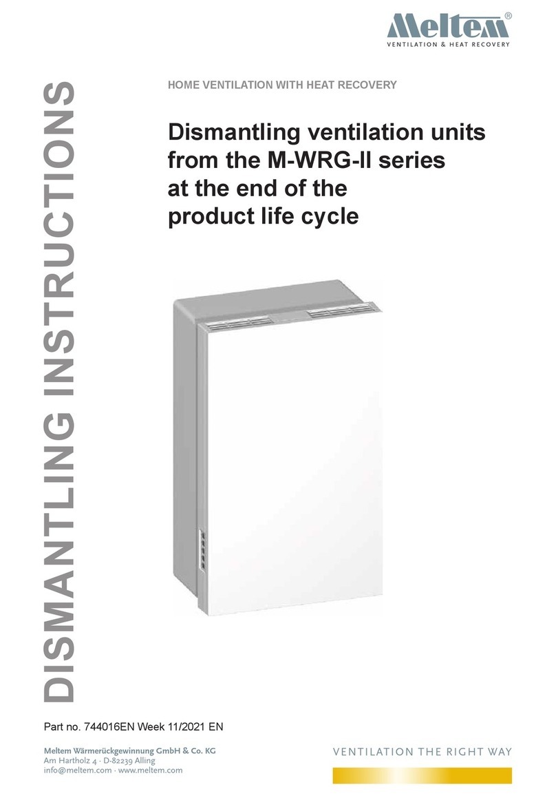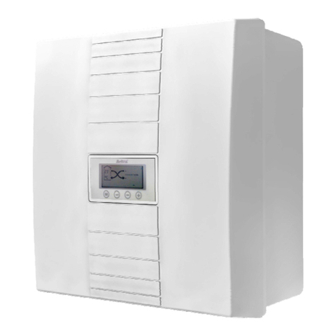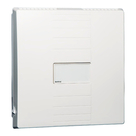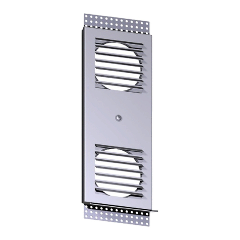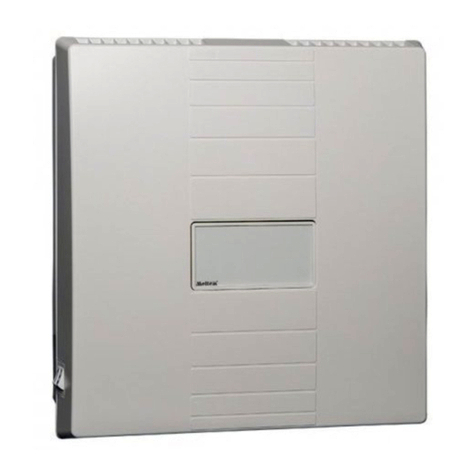
Operating and installation instructions
M-WRG-II P-T (-F, -FC), M-WRG-II E-T (-F, -FC) ventilation units
- 3 -
Meltem Wärmerückgewinnung GmbH & Co. KG
Am Hartholz 4 · D-82239 Alling
VENTILATION THE RIGHT WAY
VENTILATION & HEAT RECOVERY
6 Rules for correct usage .............................................................................................. 21
6.1 General ......................................................................................................................... 21
6.2 Seasonal operation ....................................................................................................... 21
6.2.1 Operation at cold times of year ..................................................................................... 21
6.2.2 Summer mode .............................................................................................................. 22
6.3 Airlters ........................................................................................................................ 22
7 Controls and indicators ............................................................................................. 23
7.1 Controls and indicators on the ventilation unit .............................................................. 23
7.1.1 Default assignment of the membrane touch pad .......................................................... 24
7.1.2 LED indicators on the ventilation unit ........................................................................... 25
7.2 Controls and indicators on the InControl pushbutton sensor ........................................ 26
7.2.1 InControl pushbutton sensor for type M-WRG-II P-T and M-WRG-II E-T units ............ 26
7.2.2 InControl pushbutton sensor for type M-WRG-II P-T-F and M-WRG-II E-T-F units ...... 26
7.2.3 InControl pushbutton sensor for type M-WRG-II P-T-FC and M-WRG-II E-T-FC units 27
7.2.4 Status indicators on the InControl pushbutton sensor .................................................. 27
7.3 Three-step rotary switch with zero position (provided by customer) ............................. 28
8 Starting up ................................................................................................................... 28
8.1 Checkingtheventilationunitbeforeswitchingonforthersttime ............................... 28
8.2 Switching on the ventilation unit ................................................................................... 28
9 Operating the ventilation unit .................................................................................... 29
9.1 Selecting the ventilation level/program ......................................................................... 29
9.2 Setting the ventilation unit to Standby mode ................................................................ 29
9.2.1 Activating Standby mode with the InControl pushbutton sensor .................................. 29
9.2.2 Activating Standby mode with the three-step rotary switch .......................................... 29
9.3 Optional pushbutton for intensive ventilation ................................................................ 30
9.4 Frost protection function ............................................................................................... 30
10 Ventilation levels/programs ....................................................................................... 31
10.1 “Reduced ventilation (people absent)” .......................................................................... 31
10.2 “Normal ventilation (people present)” ........................................................................... 31
10.3 “Increased ventilation” .................................................................................................. 31
10.4 “Intensive ventilation (temporary 15 min)” .................................................................... 31
10.5 “Supply air operation (summer mode)” ......................................................................... 31
10.6 “Extract air operation” ................................................................................................... 31
10.7 “Humidity control” .......................................................................................................... 32
10.8 “CO2control” ................................................................................................................. 32
10.9 “Automatic mode” ......................................................................................................... 32
11 Options for ventilation mode ..................................................................................... 33
11.1 External control input .................................................................................................... 33
11.1.1 Description .................................................................................................................... 33
11.1.2 Factory defaults and possible adjustment ranges ........................................................ 33
11.1.3 M-WRG-II O/EST-1, part no. 721005, and M-WRG-II O/EST-2, part no. 721006 ........ 33
11.2 M-WRG-II O/PARM, part no. 721000 ............................................................................ 33
11.3 M-WRG-II O/MVS, part no. 721001 .............................................................................. 34
11.4 M-WRG-II O/VOC-AUL, part no. 721002 ...................................................................... 34
11.5 M-WRG-II O/EGG-AUS, part no. 721003 ..................................................................... 34
11.6 M-WRG-II O/NOF, part no. 721004 .............................................................................. 34
11.7 M-WRG-II O/LFS, part no. 721007 ............................................................................... 35
11.7.1 Description .................................................................................................................... 35
11.7.2 Factory defaults ............................................................................................................ 35
