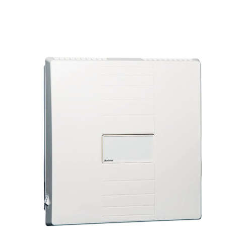
Installation manual
M-WRG-S/Z-S, M-WRG-S/Z-24,
M-WRG-S/Z-EIB, M-WRG-S/Z-KNX (-F, -FC)
- 3 -
Meltem Wärmerückgewinnung GmbH & Co. KG
Am Hartholz 4 · D-82239 Alling
VENTILATION THE RIGHT WAY
VENTILATION & HEAT RECOVERY
8.1.1 Board in M-WRG-S/Z-EIB ventilation unit ...................................................................... 16
8.1.2 EIB universal interface 6119/40 ...................................................................................... 16
8.2 Control cable types (EIB bus cable) ............................................................................... 17
8.3 Connecting the EIB universal interface 6119/40 to the ventilation unit ........................... 17
8.3.1 Removing the cover from the ventilation unit and removing the network connection
cover ............................................................................................................................... 17
8.3.2 Connecting the EIB universal interface 6119/40 to the ventilation unit’s board .............. 17
8.3.2.1 Input assignment (BCD encoding) .................................................................................. 17
8.3.2.2 Output assignment (processed by the EIB interface) ..................................................... 18
8.3.2.3 Circuit diagram for wiring without feedback .................................................................... 18
8.3.2.4 Circuit diagram for wiring with feedback ......................................................................... 19
8.4 Fixing the EIB universal interface 6119/40 in the ventilation unit and connecting the
EIB bus cable ................................................................................................................. 20
8.4.1 Fixing the EIB universal interface 6119/40 to the network connection cover ................. 20
8.4.2 Connecting the EIB bus cable to the EIB universal interface 6119/40 ........................... 20
8.5 Programming the EIB universal interface 6119/40 ......................................................... 20
8.6 Final tasks ...................................................................................................................... 20
9 Connecting the M-WRG-S/Z-KNX (-F, -FC) to the KNX bus cable ............................ 21
9.1 Overview of the modules ................................................................................................ 21
9.1.1 KNX interface ABB US/U 12.2 ........................................................................................ 21
9.1.2 Board in M-WRG-S/Z-KNX (-F, -FC) ventilation unit ...................................................... 21
9.1.3 Position of the assemblies .............................................................................................. 22
9.2 Control cable types (KNX bus cable) .............................................................................. 22
9.3 Terminal assignment of the KNX interface ..................................................................... 23
9.3.1 M-WRG-S/Z-KNX ventilation unit ................................................................................... 23
9.3.2 M-WRG-S/Z-KNX-F ventilation unit ................................................................................ 23
9.3.3 M-WRG-S/Z-KNX-FC ventilation unit ............................................................................. 24
9.4 Connecting the KNX bus cable to the KNX interface ..................................................... 25
9.5 ConguringtheKNXinterface ........................................................................................ 26
9.5.1 Assigning the physical address ...................................................................................... 26
9.5.2 Parameter settings for the KNX interface ....................................................................... 26
9.5.2.1 US/U 12.2 parameters - General .................................................................................... 26
9.5.2.2 US/U 12.2 parameters, channels A, B, C, D, I, J (switching channels for controlling
the ventilation programs in the ventilation unit) .............................................................. 27
9.5.2.3 US/U 12.2 parameters, channels E, F, G, H, K, L (feedback channels from ventilation
unit) ................................................................................................................................. 27
9.5.3 Creating the group address ............................................................................................ 28
9.5.4 KNX pushbutton sensors ................................................................................................ 28
9.5.5 Example of linking the KNX pushbutton sensor (provided by the customer) and LED
feedback ......................................................................................................................... 30
9.5.5.1 Linking with reference to the example of “Reduced ventilation” - pushbutton sensor .... 30
9.5.5.2 Linking with reference to the example of “Reduced ventilation” - LED feedback ........... 30
9.6 Final tasks ...................................................................................................................... 31
9.6.1 Fixing the KNX interface to the network connection cover ............................................. 31
9.6.2 Attaching the cover to the ventilation unit ....................................................................... 31
