TABLE
OF
CONTENTS
Item
P^
e
Number
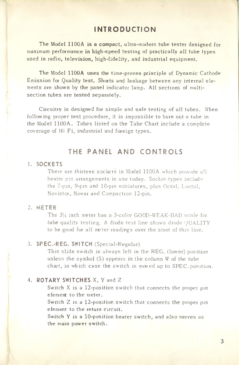
Introduction
.........................................
3
The
Panel
and
Control
.....................................................................................................
3
Te t
Procedure
..........................................................................................................................
4
A.
Preliminary
........................
.
..................................................................................
4
B.
Regular
Short
Te t
—
Cathode
Short
..................................................
4
C.
Additional
Short
Te t
-
Screen
Short
.............................................
5
D.
Quality
Te t
..........................................................................................................
6
Service
Note
............................................................................................................................
7
A.
Sample
Te t
........................................................................................................
7
B.
General
Rule
......................................................................................................
8
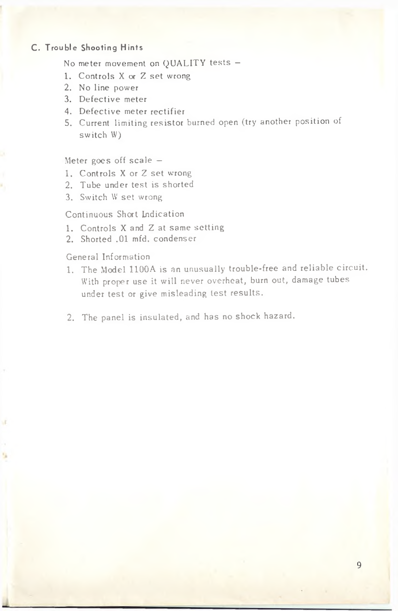
C.
Trouble hooting
Hint
.................................................................................
9
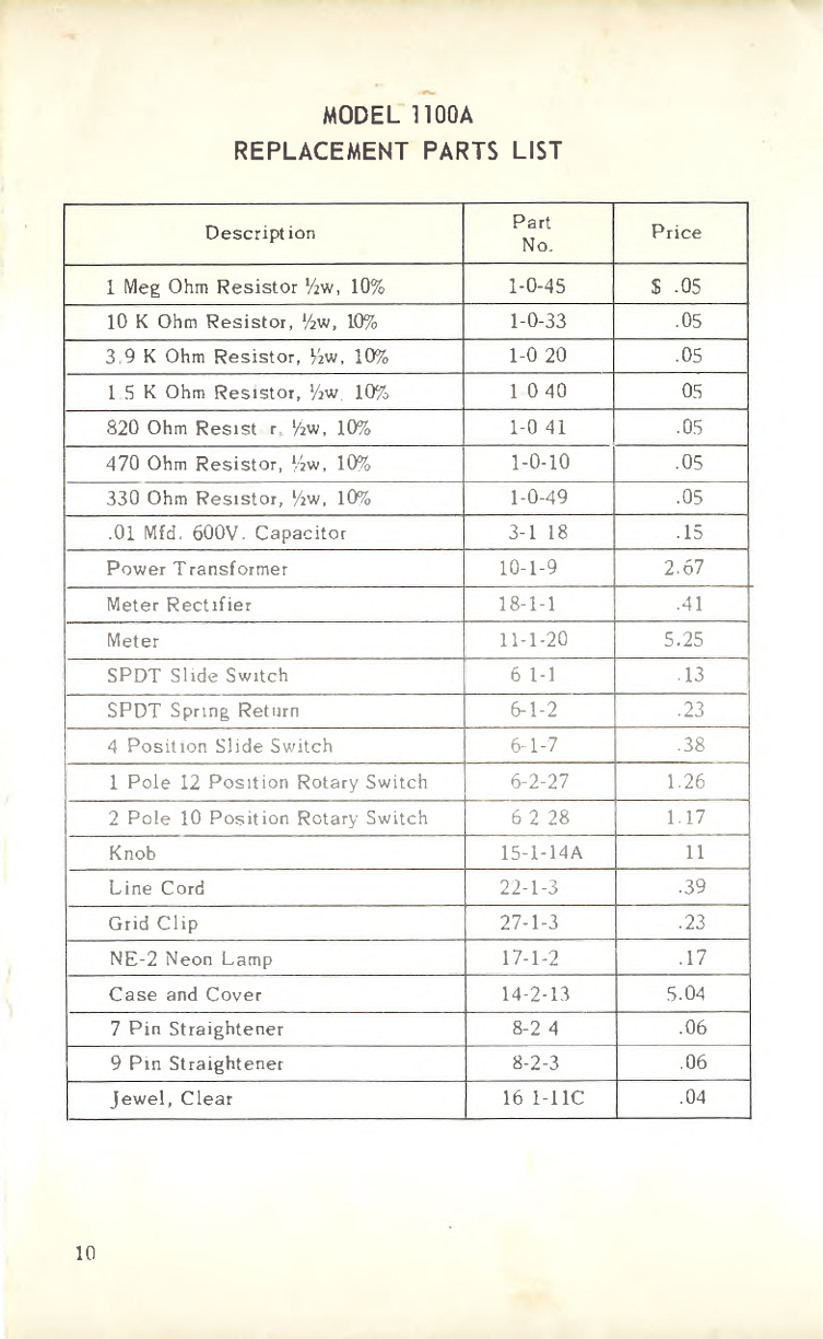
Part
Li t
.....................................................................................................................................
10
Circuit
Diagram
....................................................................................
11
MERCURY
ELECTRONICS
CORP.
MINEOLA,
NEW
YORK
65121