manuals.online logo
Brands
  1. Home
  2. •
  3. Brands
  4. •
  5. METHVEN
  6. •
  7. Plumbing Product
  8. •
  9. METHVEN Kiri Mk2 User manual

METHVEN Kiri Mk2 User manual

Technical Specification
Warranty info
Proof of purchase will be required.
The guarantee does not cover faults or damage caused by incorrect
installation and/or maintenance, ordinary wear and tear, water
composition, etc.
* Please see www.methven.com for full terms and conditions of warranty
Cleaning
Your product has a high-quality finish and should be treated with care to
preserve the visible surfaces. Never use abrasives or abrasive cleaning
agents to clean this product clean regularly with contamination free warm
water and a damp soft cloth. Do not use products containing chlorine
bleach or hydrochloric acid as these can damage the product.
Kiri Mk2 Low Flow Shower c/w Easy
Fit Kit
KRLFCTSEFLP
Installation Guide
Operating Pressure
Min:
Max:
Operating Temperature
Hot:
Cold:
1.0 Bar
5.0 Bar
65⁰C
5⁰C
Inlet Connections
15mm Compression
METHVEN UK LIMITED
METHVEN EXPERIENCE CENTRE
3/3A STONE CROSS COURT
YEW TREE WAY
GOLBORNE
WARRINGTON
WA3 3JD
UNITED KINGDOM
INST-KRLFCTSEFLP-V1
TEL: 0800 195 1602
FAX: 0844 406 8690
EMAIL: s[email protected]
www.methven.com
We have a policy of continuous improvement and reserve the right to change
specifications without notice.
Please read all of the instructions be-
fore installation.
General
Methven recommends this product
is installed by a competent person in
compliance with all relevant regional
regulations.
After installation all connenctions must
be checked for leaks.
All outlets used primarily for personal
hygiene shall deliver water at a safe
temperature as per regional regulations.
It is the responsibility of the in-
staller to ensure a waterproof seal
is achieved.
1) Use a 6mm drill bit to drill a hole in the wall at the desired height, drill a
second hole vertically lower at a recommended height of 550mm. In certain
2) Assemble the handset slider, soap dish and hose retainer on to the rail
ensuring button is facing upward. Attach both rail end assemblies.
3) Ensuring the handset slider button is facing upwards as shown in the illustra-
tion, adjust the two rail end assemblies to match the position of the wall brack-
4) Gently press the rail end assemblies onto the wall brackets, until the rail
ends touch the wall. Turn both wall covers clockwise into the locking position,
5) Insert flat washer into the shower hose before screwing to the handset. Con-
nect the other end of the shower to the shower outlet.
Testing Method
27
Installation Instructions
1) Prepare the Hot and Cold supply
pipes at 150mm centres.
2) Ensure the holes for the pipes are not
made too big as this will affect drilling of
the screw holes for the mounting brackets.
3) Ensure that there is approximately
22mm of pipework left exposed proud
of the finished tiled wall to establish
the correct installation connection.
4) Apply an appropriate amount of
sealant between the pipe and wall
lining to create a watertight seal.
5) Place the mounting plate over the
pipework.
6) Take one of the threaded connectors,
slide the connector over the pipework and
loosely fit the threaded connector into the
mounting bracket. This will ensure that
the pipework is central to the mounting
bracket.
7) Using the mounting bracket as a tem-
plate, mark the positions of the holes to
be drilled.
8) Remove the threaded connector, slide the
mounting bracket off the pipework.
9) Drill and plug the wall in position as previously
marked. Note: Ensure you use the correct type
of wall plugs to suit your particular installation
conditions.
63
Installation Instructions Continued
10) Place the mounting bracket over the pipework.
11) Place the olive over onto the exposed pipe.
12) Take one of the threaded connectors, slide the connector over the pipework
and loosely t the threaded connector into the mounting bracket.
13) Screw the mounting bracket to the wall.
14) Using two spanners, one to be located on the mounting bracket and the
other to be located on the threaded adaptor then tighten the thread adaptor
to the mounting bracket. Note: Ensure that two spanners are used to ensure
that you do not tighten the assemble against the mounting bracket screws.
Failure to do so may result in the mounting becoming loose.
15) Repeat steps 4 – 14 for the second tting, ensuring that the bar is level
on the wall.
16) To t the trim plates, screw on the threaded insert until it reaches the
nished wall lining and align accordingly. At this stage the pipe should
be ushed of any debris. Failure to do so may result in the lter of the bar
valve becoming prematurely blocked and reduce its performance.
17) Ensuring seals and lters are correctly located in the inlet unions of
the bar valve, screw the unions of the bar valve to the easy x connections
and tighten.
18) Turn on the hot and cold water supplies and check for leaks.
Commissioning and Testing
The valve should be tested to ensure correct operation at commissioning and
thereafter at stated intervals decided by the user but never greater than a 12
Monthly period.
The testing will only require a normal thermometer with a scale greater than
65⁰C. The temperature sensitive element of the thermometer should always be
fully inserted into the water flow.
Measure the mixed water temperature.
Carry out a cold fail/safe shut off test by using the isolation valve to shut off the
water to the cold supply.
Wait 5 seconds, if the water is still flowing check that the water temperature is
below 46⁰C. the flow of water should reduce to a trickle or stop completely.
Open the cold water isolation valve and measure mixed water temperature.
If there is no significant change from the original settings and the fail/safe shut
off is functioning the valve is working correctly and no further service is re-
quired.
If the outlet temperature has drifted by more than 2⁰C, or if the fail/safe func-
tion does not work, a full service or re-commissioning is required.
The manufacturer of the valve recommends that in these circumstances you
contact a competent person for servicing or ring 0800 195 1602 for further
advice.
e thermostatic mixing valve is factory set to the indicated temperature.
Check the product aer installation to ensure that it operates at the correct
outlet temperature.
A temperature dierence of at least 10⁰C should be maintained between the
mixed and system hot water.
Aer commissioning carry out a cold water failure test to ensure the valve is
operating correctly.
If some adjustment is required to the temperature, this should only be carried
out when necessary, by a competent person.
Temperature Adjustment/Commissioning
1) Turn the temperature control to the mixed position (marked 38⁰C on the
handle).
2) Turn on the water to the bath ller and using a thermometer take a tem-
perature reading.
3) If the temperature requires adjustment prise the cap out of the centre of
the temperature control handle.
4) Remove the handle screw and pull the handle o the top of the thermo-
static cartridge.
5) With the handle removed rotate the spindle, anti-clockwise to increase
clockwise to decrease.
6) Once the desired temperature is achieved re-t the handle in the mixed
position, so that the handle cannot be rotated any further clockwise without
depressing the override button.
45

This manual suits for next models

1

Other METHVEN Plumbing Product manuals
METHVEN Maku SatinJet Slide Rail Shower User manual

METHVEN

METHVEN Maku SatinJet Slide Rail Shower User manual

METHVEN PROMIX SHOWER MIXER User manual

METHVEN

METHVEN PROMIX SHOWER MIXER User manual

METHVEN MK2 User manual

METHVEN

METHVEN MK2 User manual

METHVEN SLSTWMCP User manual

METHVEN

METHVEN SLSTWMCP User manual

METHVEN KIRI User manual

METHVEN

METHVEN KIRI User manual

METHVEN 03-9753M User manual

METHVEN

METHVEN 03-9753M User manual

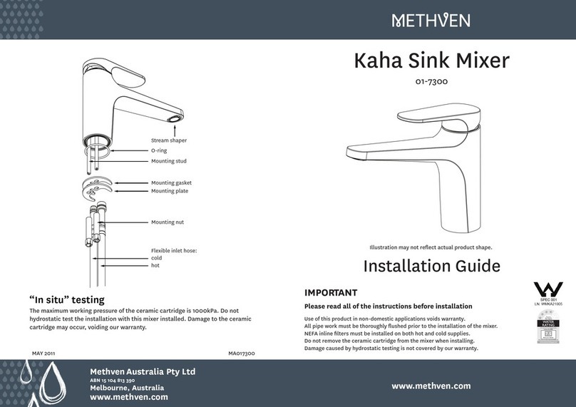
METHVEN Kaha 01-7300 User manual

METHVEN

METHVEN Kaha 01-7300 User manual

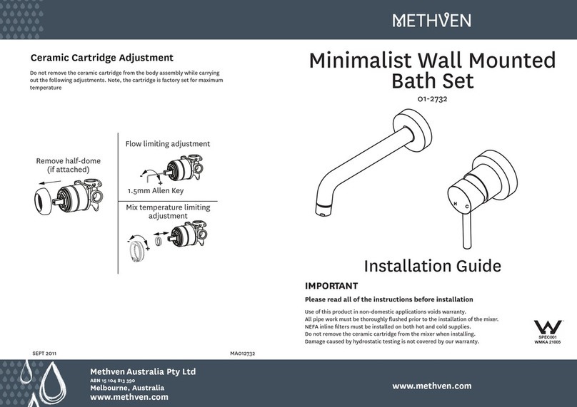
METHVEN 01-2732 User manual

METHVEN

METHVEN 01-2732 User manual

METHVEN Deva ARMC04 User manual

METHVEN

METHVEN Deva ARMC04 User manual

METHVEN 01-2138 Operating and maintenance instructions

METHVEN

METHVEN 01-2138 Operating and maintenance instructions

METHVEN Aroha 3 User manual

METHVEN

METHVEN Aroha 3 User manual
METHVEN 03-9777M User manual

METHVEN

METHVEN 03-9777M User manual

METHVEN Amio 01-4002 User manual

METHVEN

METHVEN Amio 01-4002 User manual

METHVEN SATINJET ESCAPE MKII User manual

METHVEN

METHVEN SATINJET ESCAPE MKII User manual

METHVEN Maku 01-8567 User manual

METHVEN

METHVEN Maku 01-8567 User manual

METHVEN KOHA SHOWER MIXER WITH FASTFLOW II User manual

METHVEN

METHVEN KOHA SHOWER MIXER WITH FASTFLOW II User manual

METHVEN 01-6259 User manual

METHVEN

METHVEN 01-6259 User manual

METHVEN AROHA SHOWER MIXER User manual

METHVEN

METHVEN AROHA SHOWER MIXER User manual

METHVEN Kaha 01-7409 User manual

METHVEN

METHVEN Kaha 01-7409 User manual

METHVEN 03-9432M User manual

METHVEN

METHVEN 03-9432M User manual

METHVEN Amio Shower Mixer With Divertor User manual

METHVEN

METHVEN Amio Shower Mixer With Divertor User manual

METHVEN Kiri 01-5054 User manual

METHVEN

METHVEN Kiri 01-5054 User manual

METHVEN AROHA User manual

METHVEN

METHVEN AROHA User manual
METHVEN 01-8222 User manual

METHVEN

METHVEN 01-8222 User manual

Popular Plumbing Product manuals by other brands

SUMERAIN S1248CW installation guide

SUMERAIN

SUMERAIN S1248CW installation guide

Mora MMIX Tronic Installation and maintenance  instruction

Mora

Mora MMIX Tronic Installation and maintenance instruction

Anzzi Titan SP-AZ8096 install guide

Anzzi

Anzzi Titan SP-AZ8096 install guide

Sapho WD002 installation manual

Sapho

Sapho WD002 installation manual

PEERLESS P2575LF Series quick start guide

PEERLESS

PEERLESS P2575LF Series quick start guide

KWC Suprimo 10.271.103.700 Specifications

KWC

KWC Suprimo 10.271.103.700 Specifications

Onyx 394CV Instruction

Onyx

Onyx 394CV Instruction

Bristan TY2 SDIV C Installation instructions and user guide

Bristan

Bristan TY2 SDIV C Installation instructions and user guide

Lefroy Brooks R1-4001 Installation, operating,  & maintenance instructions

Lefroy Brooks

Lefroy Brooks R1-4001 Installation, operating, & maintenance instructions

Zip HydroTap G4 Series installation instructions

Zip

Zip HydroTap G4 Series installation instructions

Kohler C3-255 installation guide

Kohler

Kohler C3-255 installation guide

Helvex 444 installation guide

Helvex

Helvex 444 installation guide

Hans Grohe M7117-H240 73817000 Instructions for use

Hans Grohe

Hans Grohe M7117-H240 73817000 Instructions for use

Harvia S1212SV Instructions for installation

Harvia

Harvia S1212SV Instructions for installation

Bradley Terreon TDWL22 Installation

Bradley

Bradley Terreon TDWL22 Installation

Spectrum Brands Pfister Arterra GT40-DE0 Quick installation guide

Spectrum Brands

Spectrum Brands Pfister Arterra GT40-DE0 Quick installation guide

American Standard Town Square 0780.001 Features & dimensions

American Standard

American Standard Town Square 0780.001 Features & dimensions

vitruvit F201BL9A User instruction

vitruvit

vitruvit F201BL9A User instruction

manuals.online logo
manuals.online logoBrands
  • About & Mission
  • Contact us
  • Privacy Policy
  • Terms and Conditions

Copyright 2025 Manuals.Online. All Rights Reserved.