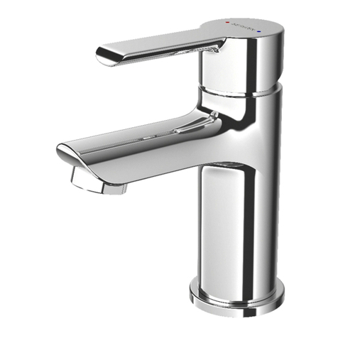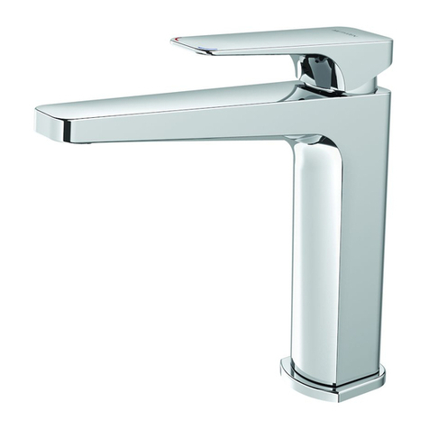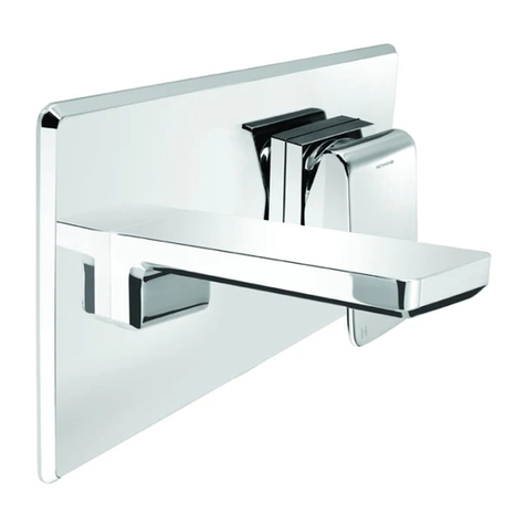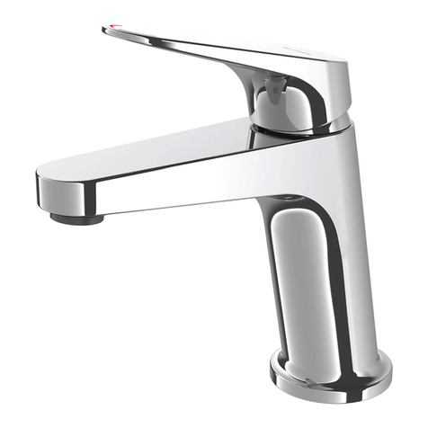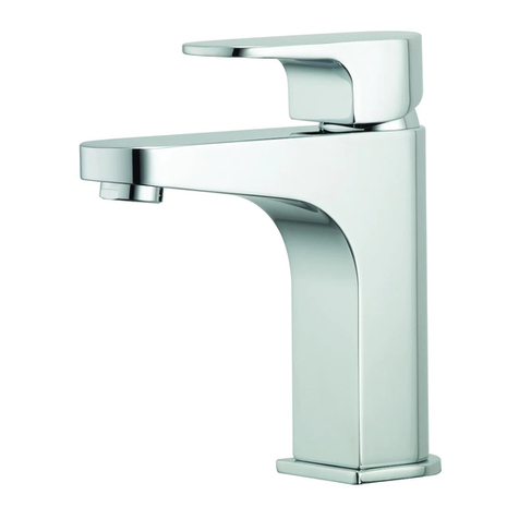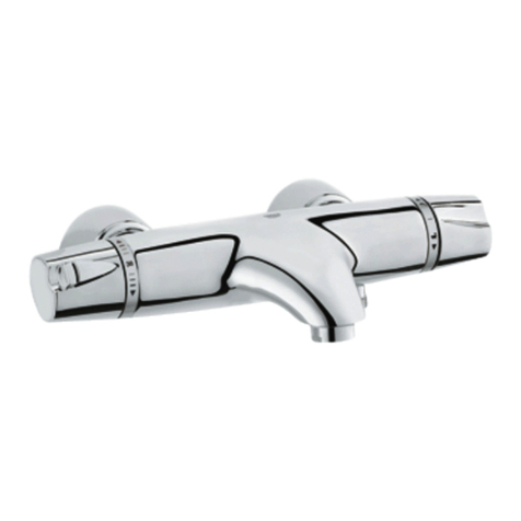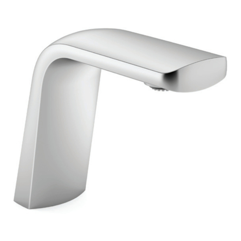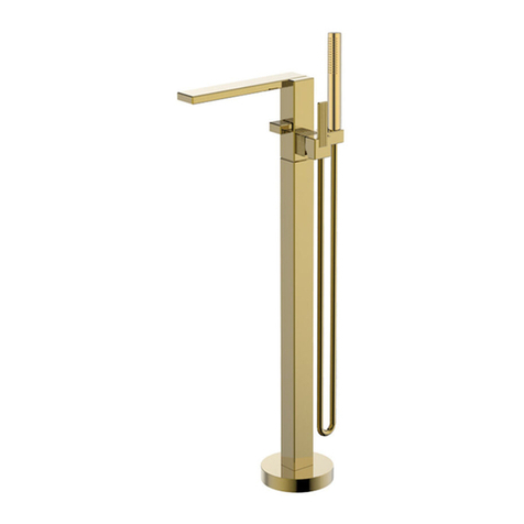
P romix S ingle Lever S ink and B asin M ixer
with adjustable cartridge for flow and temperature
2 83 91 5 Iss ue: N P age 1 of 2
Im p o rtan t – P le as e read all o f th e in s tru c tio n s b efo re i n s ta lla tio n
T he S ink M ixer is designed for A ll P ressure systems.
T he B asin Mixer is designed for M ains P ressure s ystems only.
R ecommended water supply temperature range is 5 to 65 ° C , m aximum 80° C . T hese mixers are not recommended for use
in uncontrolled heating sys tems such as wetbacks or s olar heater units unless a NE F A tempering valve is fitted. A S /NZ S
3 5 00 re quires all hot wa te r s upplie s to a ny s a nitary fittings to be tempe red to 5 5 ° C for NZ , and 5 0° C for A us tralia.
A L L P IP E W O R K M US T B E T H O R O U G HL Y F L U S H E D P R IO R T O INS T A L L A T IO N O F T H E M IX E R . A N INL INE F IL T E R
M U S T B E F IT T E D T O P R E V E NT F O R E IG N P A R T IC L E S D A M AG ING T HE C E R A M IC C A R T R ID G E .
T e ch n ic a l s p ec ific a tio n s
O peratin g P res s ure: M in: 35 kP a, M ax 1 000kP a.
R ecommended 1 5 0 – 5 00kP a . Ins ta ll a NE F A press ure limiting valve if supply pres s ure e xce eds 1 000kP a.
In let C o n n e ctio n s : A ll ½” B S P
In s ta lla tio n In s tru c tio n s S in k M ix e r
A 3 5 mm diameter hole is re quire d in the bench top.
T he bench top cannot exceed 40mm thick.
S crew the mounting studs into the bottom of the s ink
mixer.
C onnect the flexible inlet hoses to the mixer body. T he hot
hose is marked with red stainless braiding.
F it the base ring and O ring to the bas e of the sink mixer.
P lace the hos es through the bench.
F it the mounting gasket, the mounting plat
e and tighten
the mounting nuts.
T wo rubber was hers are provided for the flexible hos e
connections to the nipples. Machined nipple ends are
required to ens ure a seal to the flexible hos e nuts
In s ta llatio n In s tru c tio n s B a s in M ix e r
A 3 5 mm dia me ter hole is require d in the be nc h top.
T he bench top cannot exceed 40mm thick.
S crew the mounting studs into the bottom of the bas in
mixer.
C onnect the flexible inlet hos es to the mixer body. F it the
O ring to the bas e of the bas in.
P lace the hos es through the bench.
F it the mounting gasket, the m ounting plate and tighten the
mounting nuts.
T wo rubbe r washers are provided for the flexible hose
connections to the nipples . Machined nipple ends are
required to ens ure a seal to the flexible hos e nuts
H o s e R e qu i re m en ts
