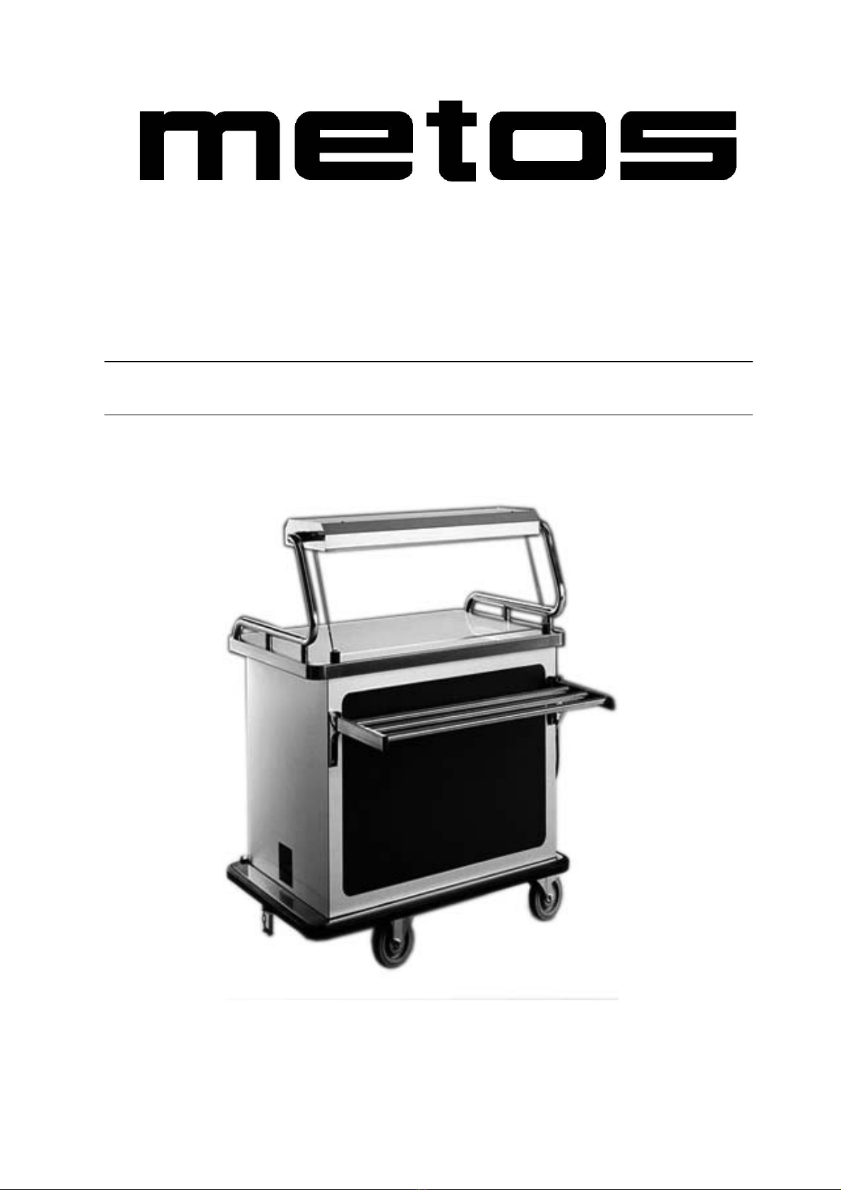
Metos Multigen User manual

Serving trolley
Multigen
Installation and operation manual

12.09.05 rev 1.0
2
1. TABLE OF CONTENTS
1. TABLE OF CONTENTS 2
2. INTRODUCTION 3
3. PRODUCT IDENTIFICATION 4
4. TROLLEY IDENTIFICATION 4
5. INTRODUCTION 5
6. SAFE MODE 6
7. CORRECT USE 6
8. WORKING ENVIRONMENT 6
9. ECOLOGICAL DISPOSAL 6
10. STANDARDS AND CERTIFICATION 7
11. PACKAGING, HANDLING, FORWARDING AND TRANSPORT 8
12. TROLLEY DESCRIPTION 9
13. SAFETY FEATURES 10
14. CONNECTING TO THE POWER SUPPLY 11
15. CONTROL PANEL 12
16. DISPLAY ON GANTRY M1 or M2 SOFTWARE 13
17. PROGRAMMING 14
18. AUTOMATIC TIMER MODULE 16
19. AUTOMATIC TIMER MODULE CONTINUED 17
20. PROGRAMMING THE AUTOMATIC TIMER SETTINGS 18
21. PROGRAMMING THE AUTOMATIC TIMER SETTINGS CONTINUED 19
22. PROGRAMMING A NEW EPROM AND LO CONDITION 20
23. PROGRAMMING THE CYCLES AND SET UP D4 AND M1 (DISP. ON GANTRY)– PLATE WARMER & AMBIENT OPTION 21
24. PROGRAMMING THE CYCLES AND SET UP D5 AND M2 (DISP. ON GANTRY)– REFRIGERATION OPTION 22
25. EXTERNAL FOOD PROBE 23
26. SPECIAL FEATURES 24
27. OPERATING INSTRUCTIONS 25
28. OPERATING INSTRUCTIONS CONTINUED 26
29. FOOD SERVICE 27
30. POST SERVICE PROCEDURE 27
31. COOK FREEZE : COOK CHILL - FLOW CHART 28
32. HOT LINE - FLOW CHART 29
33. DAILY CLEANING PROCEDURE 30
34. CLEANING SCHEDULE 30
35. REFRIGERATION FILTER 31
36. POWER WASHING 32
37. CLEANING BY HAND 32
38. TOWING ATTACHMENT 33
39. TOWING PROCEDURE FOR THE MULTIGEN 33
40. TOWING PROCEDURE FOR THE MULTIGEN DOLLIES 34
41. TOWING SAFETY MULTIGEN 35
42. FAULT FINDING 36
43. FAULT FINDING CONT. 37
44. SAFETY PARAMETERS 38
45. MAINTENANCE 38
46. REGULAR MAINTENANCE 39
47. REGULAR MAINTENANCE CONT. 40
48. CHARGING THE COMPRESSOR DOUBLE REFRIGERATION 41
49. CHARGING THE COMPRESSOR SINGLE REFRIGERATION ELECTRICAL SAFETY TESTING 42
50. ELECTRICAL SAFETY TESTING 43
51. TECHNICAL ASSISTANCE AFTER SALES SERVICE 44
52. WARRANTY AND SERVICE CALLS 45
53. SPARE PARTS 46
54. DOLLY 47
55. DIMENSIONS 48

12.09.05 rev 1.0
3
56. DIMENSIONS CONTINUED 49
57. INSTALLATION 50
58. INSTALLATION CONTINUED 51
59. ELECTRICAL SPECIFICATION 52
60. WIRING DIAGRAM 53

12.09.05 rev 1.0
4
1. Introduction
In choosing Burlodge, you have at your fingertips the most advanced purpose designed unit of its kind available today and with
careful use and regular maintenance, your unit will give you many years of trouble free use.

12.09.05 rev 1.0
5
2. Product Identification
MANUFACTURER BURLODGE Srl
ADDRESS Via CÁ BERTONCINA No 43
24068 Seriate (BG)
Tel. 0039 035 302974
Fax 0039 035 302994
TYPE OF DOCUMENT Operating and Maintenance Instructions
TYPE Regeneration/Hot Line Multi-Portion Hostess Trolley
MODEL Multigen
SERIAL NUMBER
YEAR OF MANUFACTURE
3. Trolley Identification
A data plate as shown below is attached to the rear panel of the trolley and contains all the data necessary for the identification
of the trolley.
Under no circumstances should this plate be removed, as this would invalidate the warranty. It would also no longer be
possible to identify the trolley for future technical assistance and correct spare parts.
BURLODGE S.r.l.
ITALY - 24068 SERIATE (Bergamo) Via Cá Bertoncina
Series / Série
Model / Modèle
Date / Date
Serial n. / N. de Série
Refrigerant/Réfrigérant oz
Pressure / Pression High / Haut
Psi Low / Bas
Psi
Rating / Puissance et alimentation
Oven / Four Oven / Four
Refrigerat. Refrigerat.
Options Options
Volts
Phases
Hertz
Amps
Watts

12.09.05 rev 1.0
6
4. Introduction
This manual is an integral part of the safety of your trolley and a guide for all operators and maintenance staff. It contains
important information on the operation and maintenance of your Burlodge trolley.
Ensure all personnel read this manual carefully, are fully conversant with its contents, and receive any additional training that
may be required to enable them to operate and maintain the trolley in a safe and correct manner. Pay particular attention to the
safety information included in the text.
Keep this manual in a safe place where it is accessible to all personnel at all times. This manual is a guide only and will be
supplemented by on-site training designed for your individual requirements.
It is important to note that the program settings in this manual are purely an example and will vary to the actual settings for
your trolley and site. When you receive your trolley, it will be programmed to the standard default factory settings but will be
re-programmed to suit your specific conditions.
Please Note: Before installing or using your Burlodge trolley, the power supply must be checked to ensure the voltage and
frequency correspond with the data plate. Refer to the instructions given in the” Installation” section.
it must be checked by a licensed electrician to ensure that it will be connected to an appropriate power supply. The voltage and
frequency must correspond with the data plate. Refer to the instructions given in the” Installation” section.
It is important to use the trolley only in the way that is described in this manual. Burlodge will not be responsible for any
damage that may result through incorrect use or failure to follow the instructions in this manual.
This manual relates to the Multigen 1 : Multigen 2 and Minigen series.
The following abbreviations are used in this manual to identify each individual model and options:
•Multigen I ■□
•Multigen II ■■
•Minigen ■
•Options ♦
The following symbols are used in this manual to highlight important text:
Read carefully highlights text that is important to safety
Electrical Caution Required !Caution Required
;9Correct action or procedure
:×Prohibited action or procedure

12.09.05 rev 1.0
7
5. Safe Mode
!
It is essential to have the trolley in a safe condition before any cleaning or maintenance of the trolley takes place.
This is referred to in this manual as the SAFE MODE.
The trolley is in the SAFE MODE under the following conditions:
•Full isolation from any power source.
•The plug is stored correctly in the holder, which is located on the front of the trolley.
•Oven section is at ambient temperature i.e. below 86 °F / 30 °C.
•Plate warmer ♦section is at ambient temperature i.e. below 86 °F / 30 °C.
•Heated top plate and gantry elements ♦are at ambient temperature i.e. below 86 °F / 30 °C.
•Folding tray rail ♦is in the down position.
•Lateral shelf ♦is removed from the trolley.
•Brakes are applied on the swivel castors.
•Oven fans are stationary.
6. Correct Use
Your Burlodge trolley has been designed for the following uses:
•Regeneration of Multi-portion chilled meals from +37°F to +167°F / +3°C to +75°C.
•Regeneration of Multi-portion frozen meals from -37°F to +167°F / -38°C to +75°C.
•Maintaining of Multi-portion meals above +145°F / +63°C.
•Meal service of hot and cold foods.
•Holding of cold Multi-portion meals prior to regeneration and service.
It is not recommended that the trolley be used for any other purpose than described above.
7. Working Environment
In order to guarantee the correct and safe functioning of your Burlodge trolley, it should be used in a clean, dry
environment with temperatures between +10°C (+50°F) and +30°C (+86°F) and with a maximum relative humidity of
65%.
Your Burlodge trolley must be protected from external weather conditions at all times.
8. Ecological Disposal
It is the responsibility of the user to ensure that local laws and regulations are complied with when dismantling the trolley
and disposal of all packaging and freight materials.
If your trolley is fitted with the Battery Display System option remove the battery and dispose of it correctly, before
dismantling the trolley.
!Do not dispose of it into a fire it may explode.
!Do not short circuit.
!Do not tamper or damage it.

12.09.05 rev 1.0
8
9. Standards and Certification
Technical Standards Applied
The Multigen has been designed to the following standards.
Low voltage directives
•EEC 73/23*
•EEC 93/68*
EMC directives
•EEC 89/336*
•EEC 92/31*
Technical safety standards
•EN 60335-1*
•EN 60335-2-24*
•EN 60335-2-42*
•EN 60335-2-49*
•UL 471**
•UL 197**
•CAN/CSA C22.2 No. M109-1981**
•CAN/CSA C22.2 No. 120-M91**
Technical EMC standards
•EN 55014*
•EN 55022*
•EN 55104*
•EN 61000-3-2*
•EN 61000-3-3*
Technical noise emission standards
•ISO 3744*
•ISO 12201*
Sanitary standards
•N.S.F. C2***
• * 50 Hertz models
• ** 60 Hertz models
• *** all models
** ** * ***

12.09.05 rev 1.0
9
10. Packaging, Handling, Forwarding and Transport
When received, all shipments must be inspected for any damage to the pallets or packaging. Any damage found or any
discrepancy in the number of items delivered must be noted on the carrier’s consignment note. This document shows the
number of pallets and packages delivered while an itemised description of the goods is listed on the Burlodge packing slip
attached to the consignment note. This documentation may vary.
If the packaging is not removed while the carrier is present, the terms “Unopened” or “contents unexamined” or similar should
be noted on the consignment note. The goods must be thoroughly checked for any physical signs of damage and any damage
found must be reported to Burlodge by fax or telephone within 2 days from date of delivery. A written confirmation must
follow within 5 working days together with a photocopy of the accompanying document on which the Model and Serial
number of the damaged trolley/goods must be indicated.
Unloading and handling in the Shipping/Receiving warehouse is the responsibility of the client. Burlodge is not responsible for
any damage that may occur within this area. For unloading and unpacking, proceed as follows:
Unloading:
•Unloading must be carried out by qualified staff (forklift operator) using a forklift truck with a suitable load-
bearing capacity for the weight of the trolley, which is indicated on the packaging.
•The trolley is packed on a single pallet and may contain other small items inside the trolley.
The following data is indicated on the packaging:
•Destination
•Order no.
•Pallet no.
•Gross weight
•Sender
•Contents
Unpacking:
Proceed as follows:
•Carefully cut the nylon straps.
•Remove the cardboard box.
•Cut the nylon straps holding the trolley to the wooden pallet.
•Remove the wooden slats blocking the castors.
•Unlock the brakes on the front swivel castors.
•With the use of a ramp, carefully push the trolley from the pallet. Remove the plastic bubble-wrap from the
trolley.
•At least 2 people may be required to unload the trolley from the pallet. Ensure that protective clothing and
eyewear are worn and that the correct tools are used to carry out the above operation.
•NB: the consignee, in compliance with the local laws and regulations, must dispose of packaging material.
Cleaning: The trolley should be cleaned prior to being used. Follow the instructions that are given in the “Cleaning Procedure”
section If the trolley is to be stored, it must be repacked and protected by the original packaging.

12.09.05 rev 1.0
10
11. Trolley Description
Multigen 2 side view
Multigen 1 Side View
Dolly and Module
Multigen 1-2 Front View
Minigen Front View

12.09.05 rev 1.0
11
12. Safety Features
Your Burlodge trolley includes the following built-in safety features:
Active Safety Features:
•High limit temperature thermostats.
•Microprocessor based software.
•Scrolling temperature displays of all functions.
•Thermally protected motors.
•Castors with brakes.
•Error codes.
•Auto shut down for oven probe failure.
•Low voltage control panel.
Passive Safety Features:
•Fixed fan guards.
•A.B.S. door panels for impact protection. ♦
•All-round rubber bumpers to absorb impacts.
•Positive door latches.

12.09.05 rev 1.0
12
13. Connecting to the Power Supply
Connecting
Proceed as follows:
•Ensure that the power supply is switched off before introducing the plug to the socket.
•Allow adequate space around the trolley so that it is safe and accessible
•Apply the brakes on the swivel castors.
•Ensure that the power cord is clear of any hazards and not being stretched.
•Hold the plug firmly in your hand.
•The green LED on the control panel will confirm power to the unit.
Disconnecting
Proceed as follows:
•Ensure that the brakes on the swivel castors are still applied.
•Hold the plug firmly, and withdraw it from the socket.
•Place the plug in the holder on the front of the trolley.
• The above are given as general guidelines, but may vary depending on the type of plug and socket used.
Therefore it is essential that you follow the instructions given by the manufacturer of the specific type and model
of plug and socket used.
!
•Always check the power cord before every use.
•Always hold the plug body and not the power cable to withdraw the plug.
•Always store the plug in the plug holder.
:
•Never use the trolley if there are any signs of damage or fraying to the power cord.
•Never use wet hands and ensure that both the plug and wall sockets are dry.
•Never disconnect the trolley during a retherm cycle. ALWAYS sto
p
the cycle and turn the trolley off before
disconnecting from the power supply.

12.09.05 rev 1.0
13
14. Control Panel
Touch Pads Controls And Displays
The Multigen I, Multigen II and Minigen, all have the control panel shown in the following Figure 15.1
Some of the functions are optional and may not be available or operational on your trolley. In this case the relative functions
and touch pads are disabled.
10 11 12 13 14 15
7 8 9 4 5 6 1 2 3 16
Key
Figure 15-1 Control Panel
1. Start/Stop Pad for regeneration cycle 1
2. Start/Stop Pad for regeneration cycle 2
3. Start/Stop Pad for regeneration cycle 3
3. Start/Stop Pad for maintaining cycle (press and hold for 5 seconds)*
4. On /Off Pad for Plate warmer or Refrigeration
5. On /Off Pad for Heated top plate (press once all of the top plate press twice for half top plate)*
6. On /Off Pad for cold Lights
7. Mains power indicator LED
8. Display Off Pad
9. Display On Pad
10. Display 1 indicating cycle time or error/fault messages
11. Display 2 indicating temperatures of programmed functions
12. LED indicating that the temperature of Plate warmer or Refrigerated compartment is currently being displayed
13. LED indicating that the temperature of Heated top plate is currently being displayed *
14. LED indicating that the temperature of Oven is currently being displayed.
15. LED indicating that the temperature of External food probe is currently being displayed
16. Hit system data download LED
Split Plate Warmer with refrigeration Models have a separate switch to the side of the controls to operate the Plate
Warmer section.* Refer to special features

12.09.05 rev 1.0
14
16. Display on Gantry M1 or M2 software
Touch Pads Controls And Displays
The Multigen I, Multigen II and Minigen, may have the control panel on gantry shown in the following Figure 15.2
Some of the functions are optional and may not be available or operational on your trolley. In this case the relative functions
and touch pads are disabled.
10 13 14 12 15 11 16
9 7 8 4 5 6 1 2 3
Key
Figure 15-2 Control Panel on Gantry
1. Start/Stop Pad for regeneration cycle 1
2. Start/Stop Pad for regeneration cycle 2
3. Start/Stop Pad for regeneration cycle 3
3 Start/Stop Pad for maintaining cycle (press and hold for 5 seconds)*
4. On /Off Pad for Plate warmer or Refrigeration
5. On /Off Pad for Heated top plate (press once all of the top plate press twice for half top plate)*
6. On /Off Pad for cold Lights
7. Mains power indicator LED
8. Display Off Pad
9. Display On Pad
10. Display 1 indicating cycle time or error/fault messages
11. Display 2 indicating temperatures of programmed functions
12. LED indicating that the temperature of Plate warmer or Refrigerated compartment is currently being displayed
13. LED indicating that the temperature of Heated top plate is currently being displayed *
14. LED indicating that the temperature of Oven is currently being displayed.
15. LED indicating that the temperature of External food probe is currently being displayed
16. Hit system data download LED
Split Plate Warmer with refrigeration Models have a separate switch to the side of the controls to operate the Plate
Warmer section.* Refer to special features

12.09.05 rev 1.0
15
17. Programming
Control Panel Functions when in Programming Mode
Special Touch Pad Functions and Displays in Programming Mode.
When in programming mode the touch pads on the control panel take on different functions compared to normal use.
• Display 1 indicates a two-digit number; the first digit refers to the group and the second to the sub group
• Display 2 indicates the value of the parameter which is being modified or entered.
• Cycle 1 touch pad reduces the set value of the parameter.
• Cycle 2 touch pad increases the set value of the parameter.
• Cycle 3 touch pad confirms the set value of the parameter and advances to the next parameter.
• Refrigeration/Plate Warmer pad this must be kept pressed to enter the set up under parameter O
Access to Programming Mode
• Apply the brakes on the castors.
• Connect the trolley to the power supply. The green LED will illuminate.
• Simultaneously firmly press cycle 1 and cycles 2 and 3 touch pads, press the “ON” touch pad and “P” appears on window 1.
Release cycle 1, 2 and 3 and immediately (within 5 seconds) enter the programming code
• Pressing cycle 3 and cycle 2 then cycle 1 in quick succession for set up and oven cycle programming.
• Pressing cycle 1 and cycle 2 then cycle 3 in quick succession for auto start timer programming.
• If any errors have been made in the above procedure, the panel will revert to its normal operating mode. If these instructions
have been carried out correctly “0” will appear on display 1.
Special Touch Pad Functions and Displays in Programming Mode.
When in programming mode the touch pads on the control panel take on different functions compared to normal use.
• Cycle 1 touch pad reduces the set value of the parameter.
• Cycle 2 touch pad increases the set value of the parameter.
• Cycle 3 touch pad confirms the set value of the parameter and advances to the next parameter.
When programming mode is accessed, display 1 indicates a two-digit number; the first digit refers to the group and the second
to the parameter. Display 2 indicates the parameter which is being modified or entered and represents the time in minutes or
the temperature in degrees centigrade.
Display 1 Display 2
On/Off pad Oven-cycle pads One Two and Three
Refrigeration –
Plate Warmer pad

12.09.05 rev 1.0
16
Grouping of Parameter Settings
In order to facilitate the entry of the parameters that can be set, they have been divided into four groups as shown below:
•Group “0” = settings for technical functions
•Group “1” = settings for the regeneration Cycle 1
•Group “2” = settings for the regeneration Cycle 2
•Group “3” = settings for the regeneration Cycle 3
•Group “4” = settings for the maintaining Cycle
•Group “9”= section for the serial number of the machine (please note this can only be accessed and seen when
reprogramming a new Eprom or when reprogramming After LO.
Logical Entry Sequence For Entering Parameters In Each Group
The various parameters to be entered for each group are numbered and follow the logical sequence shown below:
• Group “1” parameter “1” oven temperature setting.
• Group “1” parameter “2” total cycle time in minutes.
• Group “1” parameter “3” oven ventilation temperature setting.
• Group “1” parameter “4” duration in minutes of the ventilation cycle.
• For groups 2,3 and 4, repeat group 1 sequence.

12.09.05 rev 1.0
17
18. Automatic Timer Module
In order to facilitate the entry of the parameters that can be set, they have been divided into eight groups and further sub groups
as shown below:
•Group “1” = settings for the first weekday start of a regeneration Cycle.
•Group “2” = settings for the second weekday start of regeneration Cycle.
•Group “3” = settings for the third weekday start of regeneration Cycle.
•Group “4” = settings for the first weekend start of regeneration Cycle.
•Group “5” = settings for the second weekend start of regeneration Cycle.
•Group “6” = settings for the third weekend start of regeneration Cycle.
•Group “7” = settings for the automatic change for daylight saving, actual time, and date.
•Group “8” = settings to correct the speed of the clock.
Access To Programming Mode
•Apply the brakes on the castors.
•Connect the trolley to the power supply. The green LED will illuminate.
•Simultaneously firmly press cycle 1, 2 and 3 touch pads, press the “ON” touch pad until “P” appears on display
1. Release cycles 1, 2 and 3 and immediately (within 5 seconds) enter the programming code by pressing cycle 1,
then 2 and then 3 in quick succession
•
•If any errors have been made in the above procedure, the panel will revert to its normal operational mode. If
these instructions have been carried out correctly “CL” will appear on display 1.
•
• The following is an example to set cycle 1 for the 1st meal of the weekday and to start at 07.30.
• Access the timer-programming mode
1. “CL” in display 1
2. Press Cycle 3 and advance to group 1, which are the weekday settings for the start of the 1st meal of the day.
3. Using cycle 1 and cycle 2 (decrease and increase values) select the cycle for the start for the 1st meal of the weekday i.e.
Cycle one “01”. Press Cycle 3 to confirm the setting and to advance to the next sub group.
Using cycle 1 and cycle 2(decrease and increase values) select the value of the hour for the start of the 1st meal of the weekday
i.e. “07”. Press cycle 3 to confirm the setting and to advance to the next sub group
4. Using cycle 1 and cycle 2 (decrease and increase values) select the value of the minutes for the start of the 1st meal of
the weekday i.e. “30”. Press cycle 3 to confirm the setting and to advance to the next sub group.

12.09.05 rev 1.0
18
19. Automatic Timer Module continued
5. Using cycle 1 and cycle 2 (decrease and increase values) select the value of the hostess options for the start of the 1st
meal of the weekday i.e. cold light and refrigeration“04”. Press cycle 3 to confirm the setting and to advance to the
next sub group.
6. Continue programming all the functions to your requirements, (refer to programming data table) until you reach the
actual date and time settings. It is important to note that the actual time (group 7.8 and 7.9) must be updated every
time programming takes place as the clock is stopped when the program is accessed.
7. Press Cycle 3 to advance to group 8, this is the correction factor for the speed of the clock and should only be altered if
the clock is gaining or loosing time.
8. Press Cycle 3. Display 1 will now display “CL”
9. If any errors have been made or you wish to revise the data, you can re-access the timer program simply by pressing
Cycle 3 and continue the procedure from point 2. After any revision has been made ensure you carry out the instructions
in point 8.
Press the OFF pad and the new data will be stored into the memory.
Press the ON pad and the unit will now function as programmed. The display will now scroll between the actual temperatures
of both the oven side and the cold side followed by the actual time, (top segment of the next display flashes intermittently
when the actual time is displayed) followed by the start time of the next cycle. The next start cycle is indicated by the cycle
LED which stays on at the same time as the cycle start time.
When making any changes to the program it is important to note that you must continue to the end of the program until “CL”
is displayed. And that you press the OFF pad, otherwise the new data will not be stored and you may corrupt the unit and LO
appears on the display 1 accompanied by an audible alarm.
Important to note if the if LO is on the display then you must follow the instructions under the heading ‘Programming
a New Eprom and LO’.

12.09.05 rev 1.0
19
20. Programming the Automatic Timer Settings
Access To Programming Mode
•Simultaneously firmly press cycle 1 and cycles 2 and 3 touch pads, press the “ON” touch pad and “P” appears on window
1. Release cycle 1, 2 and 3 and immediately (within 5 seconds) enter the programming code
•Pressing cycle 1 and cycle 2 then cycle 3 in quick succession.
NB: If any errors have been made in the above procedure, the panel will revert to its normal operating mode. If these
instructions have been carried out correctly “0” will appear on display 1.
FUNCTIONS GROUPS VALUES
and Default Individual Permissible
SUB GROUPS Settings Settings range
Display 1 Display 2
C L
Do not alter settings on any of the parameters from CL to 80 unless you require the auto start timer to function
Options in Sequence Each Time Cycle 3 is pressed
1st Cycle* 11 00 00 ⇔03
Meal Hour 12 07 01 ⇔23
Of the Minutes 13 00 00 ⇔59
day Options** 14 01 00 ⇔06
2nd Cycle* 21 00 00 ⇔03
Meal Hour 22 12 01 ⇔23
Of the Minutes 23 00 00 ⇔59
day Options** 24 01 00 ⇔06
3rd Cycle* 31 00 00 ⇔03
Meal Hour 32 17 01 ⇔23
Of the Minutes 33 30 00 ⇔59
Weekday Settings
day Options** 34 01 00 ⇔06
1st Cycle* 41 00 00 ⇔03
Meal Hour 42 07 01 ⇔23
Of the Minutes 43 00 00 ⇔59
day Options** 44 01 00 ⇔06
2nd Cycle* 51 00 00 ⇔03
Meal Hour 52 12 01 ⇔23
Of the Minutes 53 00 00 ⇔59
day Options** 54 01 00 ⇔06
3rd Cycle* 61 00 00 ⇔03
Meal Hour 62 17 01 ⇔23
Of the Minutes 63 30 00 ⇔59
Weekend Settings
day Options** 64 01 00 ⇔06
Month for hour increase (+) 70 03 03
Day for hour increase (+) 71 30 30
Month for hour decrease (-) 72 10 10
Clock
Day for hour decrease (-) 73 26 26
Year 74 00
Month 75 02
Day 76 21
Day of the week*** 77 01
Hour 78 00
Date/Time
Minutes 79 00
Correction Factor
Minutes per year 800 Do not alter

12.09.05 rev 1.0
20
21. Programming the Automatic Timer Settings continued
Programming Cycle Options for Auto Start Timer
CYCLE OPTIONS for Auto Start Timer CODE
No cycle start 00
Cycle 1 01
Cycle 2 02
Cycle 3 03
HOSTESS OPTIONS CODE
No options 00
Cold light only 01
Cold light plus all of the heated top plate and gantry 02
Cold light plus the left-hand half of the heated top plate and gantry 03
Cold light and refrigeration 04
Cold light and refrigeration **** and all of heated top plate and gantry 05
Cold light and plate warmer **** and all of heated top plate and gantry 05
Cold light and refrigeration ***** and the left-half of the of heated top plate and gantry 06
Cold light and plate warmer ****and the left-half of the of heated top plate and gantry 06
Cold light and refrigeration 04
The cold light option will switch on at the end of the cycle
The refrigeration, plate warmer and top plate options will switch on 45 minutes prior to the cycle start time. The cold light
option will switch on at the end of the cycle.
**** D4 + M1 software for Multigen with the plate warmer option
***** D5 + M2 software for Multigen with the refrigeration option
Press the Off pad
The trolley is now programmed to your requirements and ready to be used
Table of contents
Other Metos Commercial Food Equipment manuals

Metos
Metos 700 Series User manual

Metos
Metos Futura HD 100L User manual

Metos
Metos Corolla M930A User manual

Metos
Metos Easy Rider Parts list manual

Metos
Metos PROFF User manual

Metos
Metos 74EFT Series User manual

Metos
Metos Ultravent Plus User manual

Metos
Metos DROP IN CB 450 User manual

Metos
Metos HALO Series User manual

Metos
Metos VIKING PRO E User manual

Metos
Metos KT-PK User manual

Metos
Metos WD-215T User manual

Metos
Metos 7210TCBG User manual

Metos
Metos 700 Series User manual

Metos
Metos BRATT PAN User manual

Metos
Metos WD-100GR User manual

Metos
Metos 700 Series User manual

Metos
Metos AGN301 GN1/1 User manual

Metos
Metos 74GFTIST User manual

Metos
Metos Nova CB User manual