manuals.online logo
Brands
  1. Home
  2. •
  3. Brands
  4. •
  5. Falcon
  6. •
  7. Commercial Food Equipment
  8. •
  9. Falcon E350/32 User guide

Falcon E350/32 User guide

T100698 Ref. 1
E350/32 and E350/33
BOILING TOPS
INSTALLATION and
SERVICING INSTRUCTIONS
IMPORTANT
The installer m st ens re that the installation of the appliance is in conformity with these instr ctions and
National Reg lations in force at the time of installation. Partic lar attention MUST be paid to -
BS7671 IEE Wiring Regula ions
Elec rici y a Work Regula ions
Heal h And Safe y A Work Ac
Fire Precau ions Ac
This appliance has been CE-marked on the basis of compliance with the Low Voltage and EMC Directives for
the voltages stated on the Data Plate
WARNING -THIS APPLIANCE MUST BE EARTHED
On completion of the installation these instr ctions sho ld be left with the Engineer-in-Charge for reference
d ring servicing. F rther to this, The Users Instr ctions sho ld be handed over to the User, having had a
demonstration of the operation and cleaning of the appliance.
IT IS MOST IMPORTANT THAT THESE INSTRUCTIONS BE CONSULTED BEFORE INSTALLING AND
COMMISSIONING THIS APPLIANCE. FAILURE TO COMPLY WITH THE SPECIFIED PROCEDURES MAY
RESULT IN DAMAGE OR THE NEED FOR A SERVICE CALL.
PREVENTATIVE MAINTENANCE CONTRACT
In order to obtain maxim m performance from this nit we wo ld recommend that a Maintenance Contract be
arranged with SERVICELINE. Visits may then be made at agreed intervals to carry o t adj stments and
repairs. A q otation will be given pon req est to the SERVICELINE contact n mbers below.
WEEE Direc ive Regis ra ion No. WEE/DC0059TT/PRO
At end of nit life, dispose of appliance and any replacement parts
in a safe manner, via a licenced waste handler.
Units are designed to be dismantled easily and recycling of all
material is enco raged whenever practicable.
Falcon Foodservice Equipmen
HEAD OFFICE AND WORKS
Wallace View, Hillfoots Road, Stirling. FK9 5PY. Scotland
SERVICELINE CONTACT -
PHONE - 01438 363 000 FAX - 01438 369 900
Warran y Policy Shor lis
Warranty does not cover :-
Correcting fa lts ca sed by incorrect installation of a prod ct.
Where an engineer cannot gain access to a site or a prod ct.
Repeat commission visits.
Replacement of any parts where damage has been ca sed by mis se.
Engineer waiting time will be chargeable.
Ro tine maintenance and cleaning.
Gas conversions i.e. Nat ral to Propane gas.
Descaling of water prod cts and cleaning of water sensors where softeners/conditioners are not fitted,
or are fitted and not maintained.
Blocked drains.
Independent steam generation systems.
Gas, water and electrical s pply external to nit.
Light b lbs.
Re-installing vac m in kettle jackets.
Replacement of grill b rner ceramics when damage has been clearly ca sed by mis se.
Where an engineer finds no fa lt with a prod ct that has been reported fa lty.
Re-setting or adj stment of thermostats when nit is operating to specification.
Cleaning and nblocking of fryer filter systems d e to c stomer mis se.
L brication and adj stment of door catches.
Cleaning and Maintenance:
Cleaning of b rner jets
Poor comb stion ca sed by lack of cleaning
L brication of moving parts
L brication of gas cocks
Cleaning/adj stment of pilots
Correction of gas press re to appliance.
Renewing of electric cable ends
Replacement of f ses
Corrosion ca sed by se of chemical cleaners.
SECTION 1 - INSTALLATION
1.2 SITING
The appliance m st be installed on a firm co nter or
table or alternatively on the special p rpose made
floor stand s pplied by Falcon.
If either appliance req ires to be installed in close
proximity to a wall, partition, etc. a clearance of 25mm
at the rear and sides is recommended.
A vertical clearance between the hotplates and any
overlying comb stible s rface of 900mm sho ld be
allowed and Fire Reg lations m st be complied with.
1.3 ELECTRICAL SUPPLY
The E350/32 is s itable for connection to a single
phase AC s pply only.
The E350/33 is designed for connection to either a
3 phase/4 wire AC s pply or to a single phase AC
s pply. (See note below.)
The cable entry is located at the rear of the appliance
and is s itable for 20mm cond it. The connection to
the mains electricity s pply m st be made thro gh a
s itable isolating switch with a contact separation of
at least 3mm in all poles. All wiring m st be exec ted
in accordance with the relevant reg lations listed on
the cover of this doc ment.
Warning
THESE APPLIANCES MUST BE EARTHED.
A s itable terminal is provided within compartment
which sho ld be sed for this p rpose.
No e
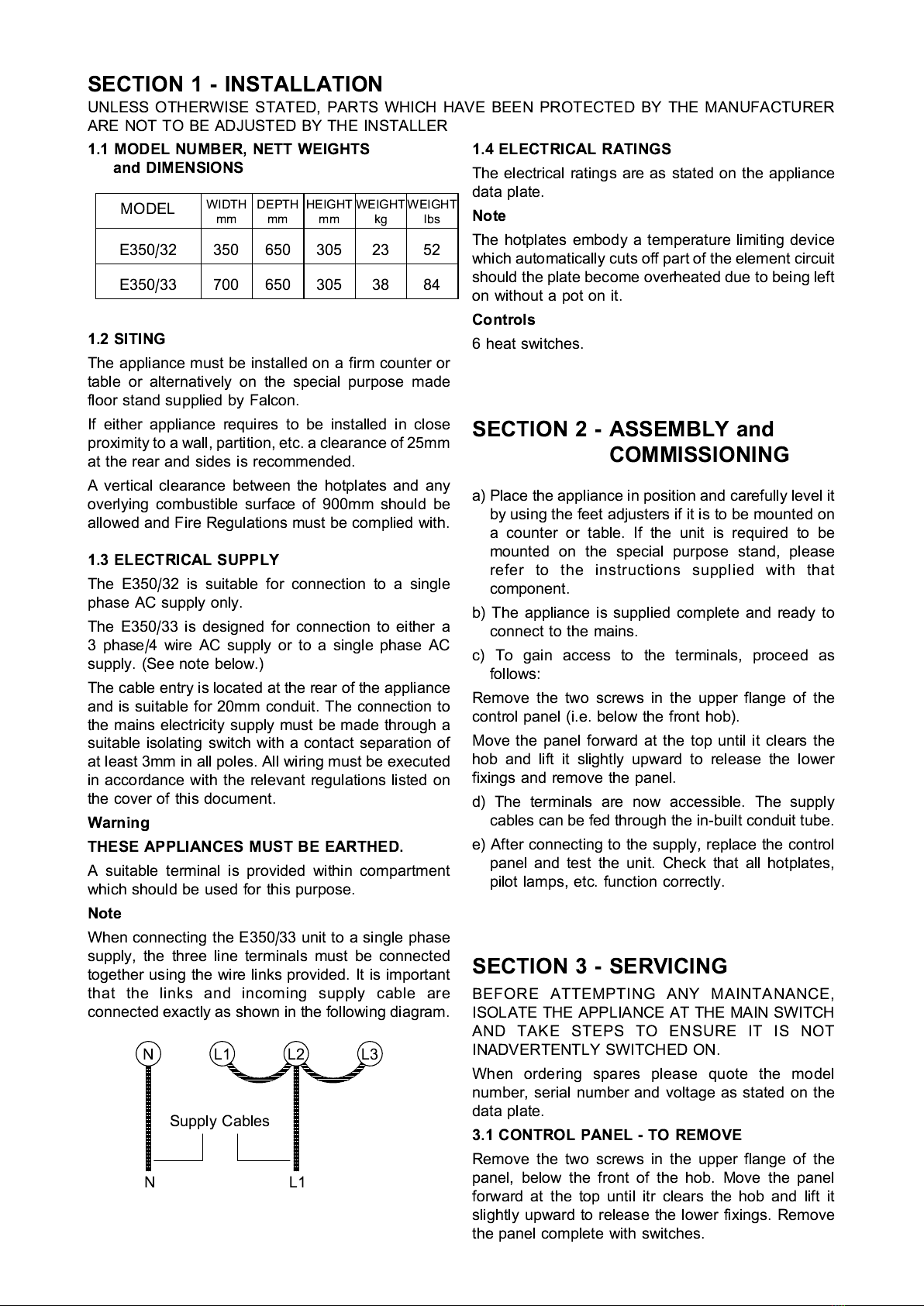
When connecting the E350/33 nit to a single phase
s pply, the three line terminals m st be connected
together sing the wire links provided. It is important
that the links and incoming s pply cable are
connected exactly as shown in the following diagram.
NL1L2L3
S pply Cables
NL1
1.4 ELECTRICAL RATINGS
The electrical ratings are as stated on the appliance
data plate.
No e
The hotplates embody a temperat re limiting device
which a tomatically c ts off part of the element circ it
sho ld the plate become overheated d e to being left
on witho t a pot on it.
Con rols
6 heat switches.
SECTION 2 - ASSEMBLY and
COMMISSIONING
a) Place the appliance in position and caref lly level it
by sing the feet adj sters if it is to be mo nted on
a co nter or table. If the nit is req ired to be
mo nted on the special p rpose stand, please
refer to the instr ctions s pplied with that
component.
b) The appliance is s pplied complete and ready to
connect to the mains.
c) To gain access to the terminals, proceed as
follows:
Remove the two screws in the pper flange of the
control panel (i.e. below the front hob).
Move the panel forward at the top ntil it clears the
hob and lift it slightly pward to release the lower
fixings and remove the panel.
d) The terminals are now accessible. The s pply
cables can be fed thro gh the in-b ilt cond it t be.
e) After connecting to the s pply, replace the control
panel and test the nit. Check that all hotplates,
pilot lamps, etc. f nction correctly.
SECTION 3 - SERVICING
BEFORE ATTEMPTING ANY MAINTANANCE,
ISOLATE THE APPLIANCE AT THE MAIN SWITCH
AND TAKE STEPS TO ENSURE IT IS NOT
INADVERTENTLY SWITCHED ON.
When ordering spares please q ote the model
n mber, serial n mber and voltage as stated on the
data plate.
3.1 CONTROL PANEL - TO REMOVE
Remove the two screws in the pper flange of the
panel, below the front of the hob. Move the panel
forward at the top ntil itr clears the hob and lift it
slightly pward to release the lower fixings. Remove
the panel complete with switches.
UNLESS OTHERWISE STATED, PARTS WHICH HAVE BEEN PROTECTED BY THE MANUFACTURER
ARE NOT TO BE ADJUSTED BY THE INSTALLER
MODEL WIDTH
mm DEPTH
mm HEIGHT
mm WEIGHT
kg WEIGHT
lbs
E350/32 350 650 305 23 52
E350/33 700 650 305 38 84
1.1 MODEL NUMBER, NETT WEIGHTS
and DIMENSIONS
3.2 CONTROL SWITCHES - TO REPLACE
If a control switch is fa lty it is not normally repairable.
The switch m st be replaced adopting the following
proced re:
Remove the control panel as detailed in Section 3.1.
Remove the switch connections, noting the
arrangements of the cables.
P ll off the control knob and ndo the switch fixing
screws to release the switch.
Fit the new switch in reverse order. Ens re that the
earth bonding wire(s) is attached to it.
3.3 PILOT LAMPS - TO REPLACE
If a lamp is fa lty it is not normally repairable. The
indicator m st be replaced adopting the following
proced re:
Remove the control panel as detailed in Section 3.1.
P ll off the lamp connections. Undo the n t which
sec res the lamp at the rear and remove.
3.4 HOTPLATE - TO REPLACE
Remove the control panel as detailed in Section 3.1.
Slacken the two n ts inside the ends of the chrome
plated side trims.
P ll the hob assembly forward to release the front
fixing and swing it pward, pivoting at the rear. Prop
the plate p in the raised position.
Undo the connections to the hotplate, noting their
locations.
Remove the central fixing n t to allow the plate to be
withdrawn from the top.
Replace in reverse order.
4
3
1
2
5
P2
P1
P3
4
3
1
2
5
P2
P1
P3
Hotplates
Six Position Switches Red Neon
E350/32 WIRING DIAGRAM
4
3
1
2
5
P2
P1
P3
4
3
1
2
5
P2
P1
P3
4
3
1
2
5
P2
P1
P3
4
3
1
2
5
P2
P1
P3
Hotplates
Six Position Switches Red Neon
E350/33 WIRING DIAGRAM

This manual suits for next models

1

Other Falcon Commercial Food Equipment manuals

Falcon E2962 User manual

Falcon

Falcon E2962 User manual

Falcon G1006X User manual

Falcon

Falcon G1006X User manual

Falcon HT2 User guide

Falcon

Falcon HT2 User guide

Falcon Dominator Plus Manual

Falcon

Falcon Dominator Plus Manual

Falcon G2962 User manual

Falcon

Falcon G2962 User manual

Falcon DOMINATOR PLUS E3405 User guide

Falcon

Falcon DOMINATOR PLUS E3405 User guide

Falcon F900 SERIES Manual

Falcon

Falcon F900 SERIES Manual

Falcon FFM-1 User manual

Falcon

Falcon FFM-1 User manual

Falcon G1478 User manual

Falcon

Falcon G1478 User manual

Falcon F-700 User manual

Falcon

Falcon F-700 User manual

Falcon E2962 User manual

Falcon

Falcon E2962 User manual

Falcon E350/40 User guide

Falcon

Falcon E350/40 User guide

Falcon G2078 User manual

Falcon

Falcon G2078 User manual

Falcon G2962 User guide

Falcon

Falcon G2962 User guide

Falcon 90 Operation manual

Falcon

Falcon 90 Operation manual

Falcon Dominator Series Manual

Falcon

Falcon Dominator Series Manual

Falcon E350/34 User guide

Falcon

Falcon E350/34 User guide

Falcon Pro-Lite LD33 User guide

Falcon

Falcon Pro-Lite LD33 User guide

Falcon FLEXI PAN Manual

Falcon

Falcon FLEXI PAN Manual

Falcon G3203 User guide

Falcon

Falcon G3203 User guide

Falcon G3203 User manual

Falcon

Falcon G3203 User manual

Falcon Dominator Plus G3800 Manual

Falcon

Falcon Dominator Plus G3800 Manual

Falcon E2962 User manual

Falcon

Falcon E2962 User manual

Falcon CHIEFTAIN E1006 User manual

Falcon

Falcon CHIEFTAIN E1006 User manual

Popular Commercial Food Equipment manuals by other brands

Fagor VPE-061 instruction manual

Fagor

Fagor VPE-061 instruction manual

Cleveland SGP Series Operation manual

Cleveland

Cleveland SGP Series Operation manual

CARTER-HOFFMANN CRISP N HOLD Operator's manual

CARTER-HOFFMANN

CARTER-HOFFMANN CRISP N HOLD Operator's manual

True TCGG-72-S-LD installation manual

True

True TCGG-72-S-LD installation manual

Omcan GR-IT-0373 instruction manual

Omcan

Omcan GR-IT-0373 instruction manual

Nemco 6152-24 Operating and maintenance instructions

Nemco

Nemco 6152-24 Operating and maintenance instructions

croydon RDACO-250001 B9 instruction manual

croydon

croydon RDACO-250001 B9 instruction manual

Eagle Director's Choice DCS4-CFRB Operation manual and instructions

Eagle

Eagle Director's Choice DCS4-CFRB Operation manual and instructions

Chocolate World M1282 manual

Chocolate World

Chocolate World M1282 manual

Fimar MCD/260E Use and maintenance

Fimar

Fimar MCD/260E Use and maintenance

Taylor C712 Operator Training

Taylor

Taylor C712 Operator Training

Ruhle IR 56 Quick installation guide

Ruhle

Ruhle IR 56 Quick installation guide

Inoksan inosmart FBG10T user manual

Inoksan

Inoksan inosmart FBG10T user manual

ARTEZEN CALYBRA HD L manual

ARTEZEN

ARTEZEN CALYBRA HD L manual

Turboair CTST-1200-N Installation and operation manual

Turboair

Turboair CTST-1200-N Installation and operation manual

True TCGG-60-S-LD installation manual

True

True TCGG-60-S-LD installation manual

ISA millennium 07 UL Operator's manual

ISA

ISA millennium 07 UL Operator's manual

croydon FZM8 Assembly, Installation and Operation

croydon

croydon FZM8 Assembly, Installation and Operation

manuals.online logo
manuals.online logoBrands
  • About & Mission
  • Contact us
  • Privacy Policy
  • Terms and Conditions

Copyright 2025 Manuals.Online. All Rights Reserved.