Metra Electronics 99-5825S User manual

INSTALLATION INSTRUCTIONS FOR PART 99-5825
APPLICATIONS
METRA. The World’s best kits.™metraonline.com1-800-221-0932 © COPYRIGHT 2004-2011 METRA ELECTRONICS CORPORATION
REV. 9/20/2012 INST99-5825
CAUTION: Metra recommends disconnecting the
negative battery terminal before beginning any
installation. All accessories, switches, and especially
air bag indicator lights must be plugged in
beforereconnecting the battery or cycling the ignition.
NOTE: Refer to the instructions included with the
aftermarket radio.
Table of Contents
• ISO DIN Head unit provision
• Driver information circuits and buttons
• Painted Silver or Matte Black to match factory finish
• A) Radio Housing • B) Radio ISO Brackets • C) (6) #8 x 3/8” Phillips truss head screws
KIT FEATURES
KIT COMPONENTS
WIRING & ANTENNA CONNECTIONS (sold separately)
Wiring Harness: • XSVI-5524-NAV Ford interface 2011-up
Antenna Adapter: • 40-EU10 multi-app adapter
• Panel removal tool • Phillips screwdriver • Socket Wrench • Cutting Tool
TOOLS REQUIRED
Ford Fiesta 2011-up
99-5825S, 99-5825B
A C
B
Dash Disassembly
–Ford Fiesta 2011-up ............................................. 2
Kit Assembly
–ISO DIN head unit provisions ................................ 3
NOTE: This kit comes pre-programmed for vehicles
equipped with SYNC. It will not operate properly in vehicles
equipped without SYNC unless it is programmed.
Programming for vehicles without SYNC:
1. Turn on the ignition.
2. Press and hold the kit’s menu button for
ten seconds.
3. Release the menu button and test the kit’s buttons
for proper operation.

99-5825
1. Unsnap and remove the panel
over the display at the top of
the dash. (Figure A)
2. Remove two 7 mm hex screws
from the top of the radio panel.
(Figure B)
3. Unclip and remove the radio
trim panel including the vents.
(Figure C)
Dash Disassembly
(Figure D)
(Figure A)
(Figure E)
(Figure B)
(Figure F)
(Figure C)
2
4. Remove two 7 mm hex holding
radio and radio chassis together
(from top of panel). (Figure D)
5. Remove two T-20 Torx and unclip
the two vents from the factory
radio panel. (Figure E)
6. Remove two T-20 Torx from
passenger airbag light and remove
it. (Figure E)
7. A small cut is required in the sub
dash for clearance. (Figure F)
Continue to kit assembly

99-5825
Kit Assembly
(Figure A)
(Figure C)
1. Snap the factory vents into the
radio panel. (Figure A)
2. Mount the ISO brackets to the
head unit with the screws supplied
with the unit. (Figure B)
3. Mount the radio bracket assembly
to the radio panel using the
supplied screws. (Figure C)
4. Mount the factory airbag indicator
to the Radio Panel using the
supplied screws. (Figure A)
(Figure A)
3
5. Locate the factory wiring
harness and antenna plug in the
dash. Metra recommends using
the proper mating adapters from
Metra and/or AXXESS.
6. Reassemble dash in reverse order
of disassembly.
NOTE: This kit comes pre-programmed
for vehicles equipped with SYNC. It
will not operate properly in vehicles
equipped without SYNC unless it is
programmed.
Programming for vehicles
without SYNC:
1. Turn on the ignition.
2. Press and hold the kit’s menu
button for ten seconds.
3. Release the menu button and test
the kit’s buttons for proper
operation.

INSTALLATION INSTRUCTIONS FOR PART 99-5825
METRA. The World’s best kits.™metraonline.com1-800-221-0932 © COPYRIGHT 2004-2011 METRA ELECTRONICS CORPORATION
REV. 9/20/2012 INST99-5825
KNOWLEDGE IS POWER
Enhance your installation and fabrication skills by
enrolling in the most recognized and respected
mobile electronics school in our industry.
Log onto www.installerinstitute.com or call
800-354-6782 for more information and take steps
toward a better tomorrow.
Metra recommends MECP
certified technicians

INSTRUCCIONES DE INSTALACIÓN PARA LA PIEZA 99-5825
AplicAciones
METRA. The World’s best kits.™metraonline.com1-800-221-0932 © COPYRIGHT 2004-2011 METRA ELECTRONICS CORPORATION
REV. 9/20/2012 INST99-5825
PRECAUCIÓN: Metra recomienda desconectar el terminal
negativo de la batería antes de comenzar cualquier
instalación. Todos los accesorios, interruptores y,
especialmente, las luces indicadoras de airbag deben
estar enchufados antes de volver a conectar la batería o
comenzar el ciclo de ignición.
Nota: Remítase a las instrucciones incluidas con el radio
de posventa.
Indice
• Provisiones de unidad central ISO DIN
• Circuitos y botones de información del conductor
• Pintada en color plateado o negro mate para igualar
el acabado de fábrica
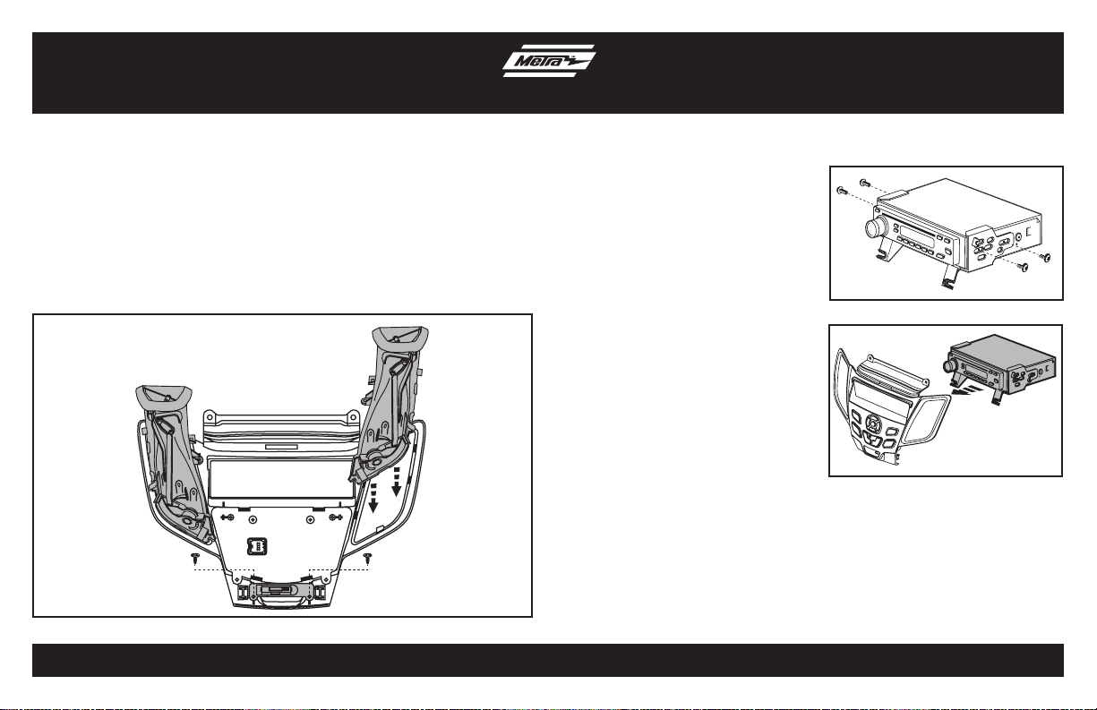
• A) Panel de moldura para radio • B) Soportes ISO para radio • C) (6) tornillos Phillips de cabeza segmentada #8 x 1/2”
cArActerísticAs del kit
componentes del kit
cABleAdo Y coneXiones de AntenA (se venden por separado)
Arnés de cableado: • Interface Ford XSVI-5824-NAV 2011 y más recientes
Adaptador de antena: • Adaptador de aplicación múltiple 40-EU10
• Herramienta para quitar paneles • Destornillador Phillips • Llave para dados
HerrAmientAs requeridAs
Ford Fiesta 2011y mas
95-5825S, 99-5825B Desmontaje del tablero
–Ford Fiesta 20011 y mas ...................................... 2
Ensamble del kit
–Provisiones de unidad central ISO DIN .................. 3
A C
B
Nota: Este kit viene pre-programado para los
vehículos equipados con SYNC. No va a
funcionar sin SYNC a menos que se programa.
Programación para vehículos sin SYNC
1. Conecte el encendido
2. Mantenga pulsado el botón del kit menú durante
10 segundos.
3. Suelte el botón del menú y probar los botones del
kit para su correcto funcionamiento.

99-5825
Desmontaje del tablero
2
1. Desenganche y quite el panel que
está sobre la pantalla en la parte
de arriba del tablero. (Figura A)
2. Quite los dos tornillos hexagonales
de 7 mm de la parte de arriba del
panel del radio. (Figura B)
3. Quite los dos tornillos hexagonales
de 7 mm que unen el radio y el
chasís del radio (de la parte de
arriba del panel). (Figura C)
4. Quite los dos tornillos Torx T-20 y
desenganche las dos rejillas del
panel del radio de fábrica.
(Figura D)
5. Quite los dos tornillos Torx T-20
de la luz de la bolsa de aire del
pasajero y quítela. (Figura E)
6. Hay que hacer un pequeño corte
en el sub tablero para hacer
espacio. Vea la foto/el dibujo...
(Figura F)
Continuará la ensamble del kit
(Figura A)
(Figura B)
(Figura C)
(Figura D)
(Figura E)
(Figura F)

99-5825
Ensamble del kit
1. Ponga a presión las rejillas de
fábrica en el panel del radio.
(Figura A)
2. Monte los soportes ISO en la
unidad central con los tornillos
incluidos con la unidad. (Figura B)
3. Monte el conjunto del soporte del
radio en el panel del radio con los
tornillos que se incluyen.
(Figura C)
4. Monte el indicador de la bolsa de
aire de fábrica en el panel del radio
con los tornillos que se incluyen.
(Figura A)
3
5. Ubique el arnés de cables de
fábrica y el conector de la antena
en el tablero. Metra recomienda
el uso de adaptadores adecuados
de acoplamiento de Metra y/o de
AXXESS.
6. Vuelva a armar el tablero al revés
de como lo desarmó.
Nota: Este kit viene pre-programado
para los vehículos equipados
con SYNC. No va a funcionar sin
SYNC a menos que se programa.
Programación para vehículos sin SYNC
1. Conecte el encendido
2. Mantenga pulsado el botón del kit
menú durante 10 segundos.
3. Suelte el botón del menú y probar
los botones del kit para su correcto
funcionamiento.
(Figura A)
(Figura B)
(Figura C)

INSTRUCCIONES DE INSTALACIÓN PARA LA PIEZA 99-5825
METRA. The World’s best kits.™metraonline.com1-800-221-0932 © COPYRIGHT 2004-2011 METRA ELECTRONICS CORPORATION
REV. 9/20/2012 INST99-5825
KNOWLEDGE IS POWER
Enhance your installation and fabrication skills by
enrolling in the most recognized and respected
mobile electronics school in our industry.
Log onto www.installerinstitute.com or call
800-354-6782 for more information and take steps
toward a better tomorrow.
Metra recomienda técnicos
con certificación del Programa
de Certificación en Electrónica
Móvil (Mobile Electronics
Certification Program, MECP).
EL CONOCIMIENTO ES PODER
Mejore sus habilidades de instalación y fabricación
inscribiéndose en la escuela de dispositivos electrónicos
móviles más reconocida y respetada de nuestra industria.
Regístrese en www.installerinstitute.com o llame al
800-354-6782 para obtener más información y avance
hacia un futuro mejor.
This manual suits for next models
1
Table of contents
Languages:
Other Metra Electronics Automobile Electronic manuals