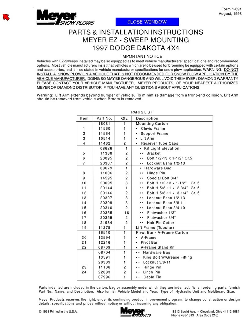
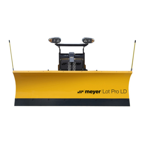
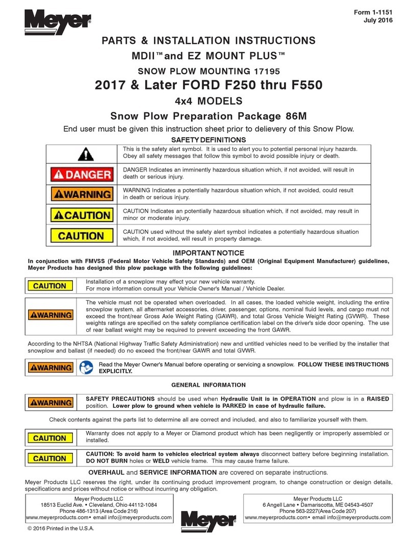
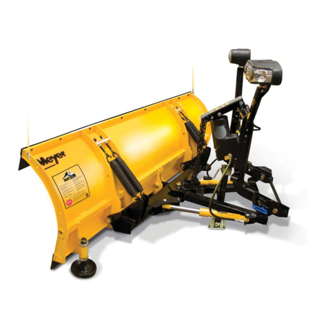
Meyer EZ-Mount Classic User manual

Operation and Maintenance Manual
SNOW PLOWS

IMPORTANT NOTICE: In conjunction with FMVSS (Federal Motor Vehicle Safety Standards) and OEM (Original Equipment Manufacturer) guidelines,
Meyer Products LLC has designed this plow package with the following guidelines:
CAUTION: Installation of a snowplow may affect your new vehicle warranty. For more information consult your Vehicle Owner’s Manual / Vehicle Dealer.
WARNING: The vehicle must not be operated when overloaded. In all cases, the loaded vehicle weight, including the entire snowplow system, all aftermarket accessories,
driver, passenger, options, nominal fluid levels, and cargo must not exceed the front/rear Gross Axle Weight Rating (GAWR), and total Gross Vehicle Weight Rating (GVWR).
These weight ratings are specified on the safety compliance certification label on the driver’s side door opening. The use of rear ballast weight may be required to prevent
exceeding the front GAWR.
According to the NHTSA (National Highway Traffic Safety Administration) new and untitled vehicles need to be verified by the installer that snowplow and ballast (if needed) do
not exceed the front/rear GAWR and total GVWR.
with certain options and accessories, and it is so stated in vehicle
manufacturer specifications for snow plow application.
WARNING: Deployment of an air bag while using a Meyer Snow
Plow will not be covered under Meyer Products’ warranty.
We also recommend that, for optimum performance, vehicles used for
snow plowing be equipped with:
• Four-Wheel Drive
• Minimum 60 Amp Alternator or larger
• Minimum 70 Amp Battery or larger (550 C.C.A.)
• Mud and Snow Tires
• Increased Radiator Cooling
• Automatic Transmission
• Power Brakes
• Power Steering
Under the continuing Meyer Product Improvement Plan, Meyer
Products LLC reserves the right to change design details and
construction without prior notice and without incurring any obligation.
Snow, despite the beauty it may impart to a bleak winter
landscape, poses the dual threat of inconvenience and danger. The
environmental conditions associated with snow, not to mention the
health hazards and economic loss it may impose, seriously endanger
thousands of lives annually. Business and industry suffer, and millions
of snowbelt residents may be affected by a single snowstorm.
Meyer Products LLC has published this manual to help you
get maximum performance from your Meyer Snow Plow and
familiarize you with the features designed for efficiency and
safety; be sure you recognize and understand them. Follow
recommended operation and maintenance instructions, so when
the storm hits, your Meyer Snow Plow will be ready and you will
know how to plow like a pro. DO NOT EQUIP ANY VEHICLE WITH
A SNOW PLOW WITHOUT CONSULTING MANUFACTURERS’
RECOMMENDATIONS.
Vehicles with Meyer Snow Plows installed may be so equipped as
to meet vehicle manufacturers’ specifications and recommended
options for snow plowing use. Most vehicle manufacturers insist
that vehicles which are to be used for snow plowing be equipped
Introduction

SAFETY FIRST
Meyer Products LLC recommends that this manual be read
cover to cover so that you, the consumer, are completely
aware of all important safety recommendations.
Table of Contents Page
Get to Know Your EZ-Mount Plus Snow Plow 2-7
Get to know your Meyer EZ-Mount Classic Snow Plow
8-11
Models of Meyer Snow Plow Moldboards 12-16
Snow Plow Operation, Maintenance & Adjustments 17-21
Hydraulic Power Unit Diagnosis Charts 22-24
Efficient Snow Clearance Starts with Planning 25
Plow with the Storm 26
Two Established Snow Clearance Plans 27
Snow Plowing Tips from the Pros 28-30
Minerals & Chemicals for Snow & Ice Control 31
Meyer Spreaders 32-33
Meyer Accessories 34-36
Genuine Meyer Parts 37-40
Meyer Warranty Back Cover
Meyer Registration Card Back Cover
1
www.meyerproducts.com
e-mail [email protected]
SAFETY FIRST
Meyer Products recommends that this manual be read cover to cover so
that you are completely aware of all important safety recommendations.
Record your E-58H Serial Number and Moldboard Serial Number. These
serial numbers are printed on the E-58H unit decal and on the back of the
Moldboard on the part number decal
Be sure to REGISTER your Snow Plow Sys-
tem online at www.meyerproducts.com to
ensure maximum warranty protection.
Hydraulic Lift Serial Number _________________
Moldboard Serial Number ___________________
THE INDUSTRY’S BEST
WARRANTY PROTECTION
2 YEARS STANDARD ON ALL COMPONENTS
3 YEARS ON ALL COMPONENTS*
5 YEARS ON ALL STRUCTURAL STEEL*
* Register at www.meyerproducts.com to activate years 3-5.

2
1. Moldboard
Steel or Polyethylene sheet is bump and corrosion resistant. Built
to last.
2. Cutting Edge
Replaceable high carbon steel provides extra long operating life;
should be 1/2” above ground in plowing position. (Can be higher
when used on gravel driveways.)
3. Runners
Adjustable and replaceable runners hold cutting edge at proper
height.
4. Trip Springs
Allow moldboard to trip forward and ride over obstructions, this
protects the snow plow, vehicle, and operator.
5. Sector
High quality steel - positions moldboard straight across, or angle
right or left.
6. Pivot Pin
Pin that attaches the moldboard to the sector.
7. A-Frame
Designed to attach the snow plow to the vehicle, to pivot moldboard
for angle plowing, and to hold plow at proper distance in front of
vehicle.
8. Power Angling Cylinders (1-1/2” x 10”)
Hydraulically positions the moldboard straight, or to right or left.
9. Clevis Frame
Allows snow plow assembly to be attached or detached from vehicle
in minutes.
10. Lift Frame
Allows for fast, complete removal of front end hardware, snow plow,
lights and hydraulic unit in one complete module.
11. Attaching Pins
Pull 2 blue pins to remove complete assembly.
12. Lift Arm
Dual Chain locks in position to lift snow plow.
WARNING: LIFT ARM EXTENDS BEYOND BUMPER OF VEHICLE.
TO MINIMIZE DAMAGE FROM A FRONT END COLLISION, LIFT
ARM SHOULD BE REMOVED FROM VEHICLE WHEN SNOW
PLOW IS REMOVED.
13. Meyer Nite Saber® Snow Plow Lights
Complies with the Federal Motor Vehicle Safety Standards.
14. Electric Hydraulic Power Unit (E-58H)
Operates snow plow hydraulically- raises, lowers, angles, holds and
floats moldboard in plowing position.
15. Sno-Flo® Powder Coat
Baked on finish that looks like enamel, provides an extremely hard,
low friction surface that outlasts ordinary paint by a large margin.
Applied to all steel moldboards and mountings/frames.
16. Crankstand
Positions Moldboard and Lift Frame for easy attaching and
detaching.

3
13
16
12
10
11
Blue
E-58H (14)

CRANKSTAND STORAGE
To store Crankstand on the Lift Frame slide the tube that is
attached to the side of the Crankstand over the receiver tube on
the driver’s side of the Lift Frame. Insert the chain locking pin
through the vertical holes on both the tubes. Note: Crankstand
should always be fully retracted (up) and be pinned in the
vertical transport position when not in use. Receiver Tube
Cap may be placed over the driver side transport tube while the
Crankstand is in use on the A-Frame. The Receiver Tube Cap
may also be switched over to the Adjustment Tube of the A-Frame
when the Crankstand is mounted to the Lift Frame.
Storage of the Crankstand is the responsibility of the
operator. The stand can be stored on the lift frame in the
retracted position to the driver’s side transport tube or inside
the vehicle cab.
4

DETACHING THE COMPLETE ASSEMBLY
Leave control switch in lower float position and push down on
the Lift Arm. Disconnect the electrical plug and slip on weather
caps over the both ends. Attach Crankstand to the adjustment
tube in the center of the A-Frame using the chained locking pin.
Caution: Crankstand must be secured at all times. Adjust the
Crankstand down until the bottom of stand touches the ground.
Pull and twist the Blue Handle Pins to disengage. If the pins do
not pull easily, adjust stand up or down slightly to remove tension
on the pins until they disengage. At this time the lift frame should
be leaning forward slightly, at rest on the top of the Crankstand.
Pull truck away.
ATTACHING THE COMPLETE ASSEMBLY
Check that Blue Handle Pins are disengaged. Drive the truck up
to the EZ-Mount Plus assembly centering the hood of the truck
to the lift arm to assure proper alignment with lift frame guide
plates until contact is made. Once contact is made drive forward,
pushing the assembly a few inches. This insures the A-Frame is
square to the Clevis Frame for proper pin attachment. Adjust the
Crankstand up until the front of the truck raises slightly. Twist Blue
Handle Pins so that the small leg re-aligns with the slot, engaging
the pins. The spring loaded pins should snap into place. Note: If
pins do not lock immediately, move truck slightly forward and/or
adjust the Crankstand up or down until pins engage, or push 5
Blue Handle
Crankstand
the top of the Lift Frame towards the truck locking the pins to
the clevis frame. Remove the Crankstand from the A-frame by
removing the chained locking pin. Reattach the Crankstand to the
transport tube on the driver’s side of the Lift Frame in the vertical,
retracted position. Caution: Crankstand must be secured at
all times. Reattach the one step electrical connection.

6
Lower Plow to float position and manually
push lift arm down. Disconnect the electrical
connection.
Remove crankstand from storage
position on the side of mount and
reattach to “A” frame. Crank until front
of truck rises slightly.
Pull, then rotate blue pins on both sides of
truck into locked out position. The vehicle
is now free from mount and may safely
back away.
Removal
12 3
(back)
(front)
12
3
4

7
Drive into assembly until contact is made
and push assembly a few inches forward.
Rotate blue pins until engaged and push
top of lift frame towards truck until pins
click in place.
Return crankstand to storage position and
reattach the electrical connection. The
mount is now securely attached to the
vehicle and is operational.
Attachment
1 2 3
Always confirm pins are fully engaged before over the road or snow plow operation.

8
1. Moldboard
Steel or polyethylene sheet is bump and corrosion-resistant. Built
to last.
2. Cutting Edge
Replaceable, high carbon steel provides extra long operating life;
should be 1/2” above ground in plowing position. (Can be higher
when used on gravel driveways.)
3. Runners
Full-swivel adjustable and replaceable runners hold cutting edge at
proper height.
4. Trip Springs
Allow moldboard to trip forward and ride over obstructions without
losing snow load—protects snow plow, vehicle, and operator.
5. Sector/5A Pivot Bar
High quality steel—positions moldboard straight across, or angle
right or left.
6. Pivot Pin
Pin that attaches moldboard to sector.
7. A-Frame
Designed to attach snow plow to vehicle, to pivot moldboard for
angle plowing, and to hold plow at proper distance in front of
vehicle.
8. Power Angling Cylinders
Hydraulically positions the moldboard straight, or to right or left.
9. Clevis Frame
Allows adjustment of the Snow Plow A-Frame attaching point
(clevis height) for transfer of power from the vehicle frame to the
snow plow. Clevis frame weather plugs (Item 17) protect receiver
tubes from dirt and moisture when lift frame (Item 12) is removed.
Note: Adjustment bolt threads should be coated with chassis
grease or anti-seize lubricant. Adjust bolts for minimum
clearance between lift frame and receiver tubes while still
allowing for ease of lift frame removal.
10. Linch Pins
Allow snow plow assembly to be attached or detached from
vehicle in minutes.
11. Tubular Lift Frame (EZ Mount® Classic only)
Allows for fast, complete removal of front end hardware, snow
plow lights and hydraulic unit in one complete assembly.
12. Lift Arm
Chain locks in position to lift snow plow.
WARNING: LIFT ARM EXTENDS BEYOND BUMPER OF
VEHICLE. TO MINIMIZE DAMAGE FROM A FRONT-END
COLLISION, LIFT ARM SHOULD BE REMOVED FROM
VEHICLE WHEN SNOW PLOW IS REMOVED.
13. Meyer Nite Saber® Lights
Complies with the Federal Motor Vehicle Safety Standards.
14. Electric Hydraulic Power Unit
Operates snow plow hydraulically—raises, lowers, angles, holds
and floats moldboard in plowing position.
15. Sno-Flo® Powder Coat
Baked on finish that has an enamel like appearance, provides an
extremely hard, low friction surface that outlasts ordinary paint by
a large margin.
16. Weather Cap
Slide on receiver tube when lift frame assembly is removed.

14
9
11
16
Weather Cap
12
13
9
15
1
3
2
8
4
10
6
5
7
15
4
2
1
38
5A
Runner
RECEIVER TUBE
LIFT FRAME
ADJUSTING BOLT
RIB
A-Frame Sector
King Bolt
SECTOR TO A-FRAME ASSEMBLY
7
10

Clevis Frame
Center Hole
Weather Cap
Hinge Pins
Removing Moldboard and
Lift Frame Assembly
1. Be sure moldboard is on ground! The chain can have a small
amount of tension to help support the back of the A-Frame. At this
time use a wood block to slide under the back of the A-Frame to
support and maintain level position for reattaching.
2. Remove right and left side hinge pins from A-Frame at center hole
in clevis frame.
3. Uncouple the hydraulic hoses and interconnect the hydraulic quick
couplers to prevent dirt contamination from getting in the system.
(requires optional coupler kit 07087C)
4. Lower the lift arm all the way down and detach the chain from the
lift arm.
5. Slowly back vehicle away.
If desired you may also remove the lift frame, lights, and electric
hydraulic pump assembly.
1. Remove right and left linch pin and hinge pin from receiver tube.
2. Unplug all electrical connections.
3. Slide entire lift frame assembly out. CAUTION: Lift frame
assembly weighs approximately 115 lbs. and to properly
manage this assembly two people are required.
To reattach moldboard and A-Frame or lift frame assembly reverse
above procedure.
10

ADJUSTING CHAIN FOR PROPER SLACK WHEN PLOWING
SNOW
1. Be sure moldboard is on ground and A-frame is reattached
at center hole in clevis frame.
2. Be sure lift piston is fully retracted.
3. Hold chain taut and choose the third link above lift arm,
place that link in lift arm locking groove. This procedure will
provide the proper amount of slack when snow plowing for
the moldboard to follow the contour of the ground. You may
wish to mark that link with paint or tape for easy
identification. Due to the differences in vehicle
ride heights, extra chain links may vary in length.
To prevent the extra chain links from causing
damage, remove or secure the chain links
together using an electrical tie strap.
11

Models TM-6, TM-6.5
For 4x4 Down Sized Pickups
and Sport Utility Vehicles
STEEL MOLDBOARD SPECIFICATIONS
SNOW PLOW MODEL TM-6 TM-6.5
MOLDBOARD LENGTH 6’ 6 1/2’
MOLDBOARD HEIGHT 23” 23”
MOLDBOARD GAUGE 14 14
VERTICAL RIBS 4 4
NO. OF TRIP SPRINGS 2 2
CUTTING EDGE 3/8” x 6” 3/8” x 6”
PLOWING WIDTH 64” 69”
AT FULL ANGLE
SECTOR - -
POWER ANGLING RAMS 1 1/2” x 10” 1 1/2” x 10”
*AVERAGE PLOW 380 lbs. 400 lbs.
WEIGHT COMPLETE
Models TMP-6.5, TMP-7
For Down Sized Pickups
and Sport Utility Vehicles
MAX POLYETHYLENE SPECIFICATIONS
SNOW PLOW MODEL TMP-6.5 TMP-7
MOLDBOARD LENGTH 6 1/2’ 7’
MOLDBOARD HEIGHT 23” 23”
MOLDBOARD GAUGE 3/8” 3/8”
Polyethylene Polyethylene
VERTICAL RIBS 4 4
NO. OF TRIP SPRINGS 2 2
CUTTING EDGE 3/8” x 6” 3/8” x 6”
PLOWING WIDTH 69” 74”
AT FULL ANGLE
SECTOR - -
POWER ANGLING RAMS 1 1/2” x 10” 1 1/2” x 10”
*AVERAGE PLOW 400 lbs. 424 lbs.
WEIGHT COMPLETE
TRIMLINE SERIES
6’, 6 1/2’, 7’, 7 1/2’ Diamond Blade
For Skid-Steer
Vehicles
STEEL MOLDBOARD SPECIFICATIONS
SNOW PLOW MODEL DTE-6 DTE-6.5 DTE-7 DTE-7.5
MOLDBOARD LENGTH 6’ 6 1/2’ 7’ 7 1/2’
MOLDBOARD HEIGHT 26 1/2” 26 1/2” 26 1/2” 26 1/2”
MOLDBOARD GAUGE 12 12 12 12
VERTICAL RIBS 6 6 6 6
NO. OF TRIP SPRINGS 4
extension
4
extension
4
extension
4
extension
CUTTING EDGE 1/2” x 6” 1/2” x 6” 1/2” x 6” 1/2” x 6”
PLOWING WIDTH 62” 68” 73” 78”
AT FULL ANGLE
SECTOR - - - -
POWER ANGLING RAMS
1 1/2” x 10” 1 1/2” x 10” 1 1/2” x 10” 1 1/2” x 10”
*AVERAGE PLOW 529 lbs. 543 lbs. 557 lbs. 578 lbs.
WEIGHT COMPLETE
12
*weight is based on average depending on specific mounting

Models STP-7, STP-7.5
For 4x4 Standard Duty Pickups
and Sport Utility Vehicles
NOTE: STP-7 standard with 2 trip springs.
MAX POLYETHYLENE SPECIFICATIONS
SNOW PLOW MODEL STP-7 STP-7.5
MOLDBOARD LENGTH 7’ 7 1/2’
MOLDBOARD HEIGHT 27” 27”
MOLDBOARD GAUGE 3/8” 3/8”
Polyethylene Polyethylene
VERTICAL RIBS 4 4
NO. OF TRIP SPRINGS 2 3
CUTTING EDGE 3/8” x 6” 3/8” x 6”
PLOWING WIDTH 74” 79”
AT FULL ANGLE
SECTOR 11” 11”
POWER ANGLING RAMS 1 1/2” x 10” 1 1/2” x 10”
*AVERAGE PLOW 621 lbs. 660 lbs.
WEIGHT COMPLETE
Models ST-7, ST-7.5, STL-7.5
For 4x4 Standard Duty Pickups
and Sport Utility Vehicles
NOTE: ST-7 standard with 2 trip springs.
STEEL MOLDBOARD SPECIFICATIONS
SNOW PLOW MODEL ST-7 ST-7.5 STL-7.5
MOLDBOARD LENGTH 7’ 7 1/2’ 7 1/2’
MOLDBOARD HEIGHT 25” 25” 25”
MOLDBOARD GAUGE 12 12 14
VERTICAL RIBS 4 4 4
NO. OF TRIP SPRINGS 2 3 3
CUTTING EDGE 3/8” x 6” 3/8” x 6” 3/8” x 6”
PLOWING WIDTH 74” 79” 79”
AT FULL ANGLE
SECTOR 11” 11” 11”
POWER ANGLING RAMS 1 1/2” x 10” 1 1/2” x 10” 1 1/2” x 10”
*AVERAGE PLOW 580 lbs. 606 lbs. 469 lbs.
WEIGHT COMPLETE
STANDARD SERIES
13
*weight is based on average depending on specific mounting

Models CP-7.5, CP-8, CP-8.5, CP-9.0
For 4x4 Heavy Duty 3/4 ton, 1 ton Pickups,
and 1 ton Cab Chassis
MAX POLYETHYLENE SPECIFICATIONS
SNOW PLOW MODEL CP-7.5 CP-8 CP-8.5 CP-9.0
MOLDBOARD LENGTH 7 1/2’ 8’ 8 1/2’ 9’
MOLDBOARD HEIGHT 30” 30” 30” 30”
MOLDBOARD GAUGE 3/8” 3/8” 3/8” 3/8”
Polyethylene
VERTICAL RIBS 6 6 6 6
NO. OF TRIP SPRINGS 4 4 4 4
CUTTING EDGE 3/8” x 6” 1/2” x 6” 1/2” x 6” 1/2” x 6”
PLOWING WIDTH 79” 84” 88” 93”
AT FULL ANGLE
SECTOR 15” 15” 15” 15”
POWER ANGLING RAMS
1 1/2” x 10” 1 1/2” x 10” 1 1/2” x 10” 1 1/2” x 10”
*AVERAGE PLOW 791 lbs. 821 lbs. 840 lbs. 868 lbs.
WEIGHT COMPLETE
Models C-7.5, C-8, C-8.5, C-9
For 4x4 Heavy Duty 3/4 ton, 1 ton Pickups,
and 1 ton Cab Chassis
STEEL MOLDBOARD SPECIFICATIONS
SNOW PLOW MODEL C-7.5 C-8 C-8.5 C-9
MOLDBOARD LENGTH 7 1/2’ 8’ 8 1/2’ 9’
MOLDBOARD HEIGHT 28” 28” 28” 28”
MOLDBOARD GAUGE 12 12 12 12
VERTICAL RIBS 6 6 6 6
NO. OF TRIP SPRINGS 4 4 4 4
CUTTING EDGE 3/8”x 6” 1/2” x 6” 1/2” x 6” 1/2” x 6”
PLOWING WIDTH 79” 84” 88” 93”
AT FULL ANGLE
SECTOR 15” 15” 15” 15”
POWER ANGLING RAMS 1 1/2” x 10” 1 1/2” x 10” 1 1/2” x 10” 1 1/2” x 10”
*AVERAGE PLOW 729 lbs. 759 lbs. 797 lbs. 802 lbs.
WEIGHT COMPLETE
CONTRACTOR SERIES
14
*weight is based on average depending on specific mounting

Models HMP-10
For trucks with a G.V.W. of 16,000 to 27,000
MAX POLYETHYLENE SPECIFICATIONS
SNOW PLOW MODEL HMP-10
MOLDBOARD LENGTH 10’
MOLDBOARD HEIGHT 36”
MOLDBOARD GAUGE 3/8 POLY
VERTICAL RIBS 7
NO. OF TRIP SPRINGS 6
CUTTING EDGE 1/2” x 6”
PLOWING WIDTH 103”
AT FULL ANGLE
SECTOR 15”
POWER ANGLING RAMS 2” x 12”
*AVERAGE PLOW 1271 lbs.
WEIGHT COMPLETE
Models HM-9, HM-10
For trucks with a G.V.W. of 16,000 to 27,000
STEEL MOLDBOARD SPECIFICATIONS
SNOW PLOW MODEL HM-9 HM-10
MOLDBOARD LENGTH 9’ 10’
MOLDBOARD HEIGHT 32” 32”
MOLDBOARD GAUGE 7 7
VERTICAL RIBS 7 7
NO. OF TRIP SPRINGS 6 6
CUTTING EDGE 1/2” x 6” 1/2” x 6”
PLOWING WIDTH 93” 103”
AT FULL ANGLE
SECTOR 15” 15”
POWER ANGLING RAMS 2” x 12” 2” x 12”
*AVERAGE PLOW 1205 lbs. 1254 lbs.
WEIGHT COMPLETE
HEAVY MUNICIPAL SERIES
15
*weight is based on average depending on specific mounting

SNOW PLOW MODEL AGP-10 AGC-10
MOLDBOARD LENGTH 120” 120”
MOLDBOARD HEIGHT 36” 36”
MOLDBOARD GAUGE 3/8” POLY 10
VERTICAL RIBS 8 8
NO. OF TRIP SPRINGS 6 6
CUTTING EDGE 1/2” x 6” 1/2” x 6”
PLOWING WIDTH 98” 98”
AT 35° ANGLE
POWER ANGLING RAMS
2-1/2” x 11-1/2”
2-1/2” x 11-1/2”
*AVERAGE PLOW 1590 lbs. 1610 lbs.
WEIGHT COMPLETE w/o options w/o options
Model HML-10
For Chevy/GMC trucks model HD3500 and 4500/5500
and Ford F-450, F-550
SPECIFICATIONS
HEAVY MUNICIPAL SERIES
16
Aggressor Models AGP-10, AGC-10
For vehicles up to 33,000 GVW
SPECIFICATIONS
SNOW PLOW MODEL HML-10
MOLDBOARD LENGTH 10’
MOLDBOARD HEIGHT 32”
MOLDBOARD GAUGE 10
VERTICAL RIBS 7
NO. OF TRIP SPRINGS 6
CUTTING EDGE 1/2”x 6
PLOWING WIDTH 103”
AT FULL ANGLE
SECTOR 15”
POWER ANGLING RAMS 1 1/2” x 10”
WEIGHT COMPLETE 1,020 lbs.
*weight is based on average depending on specific mounting

The snow plow should only be in operation when the vehicle ignition
switch and the Electro-Touch
®
control switch are in the “ON” position.
Care should be taken to insure that the Electro-Touch® control switch
is kept dry and free from moisture during normal operation.
When the Electro-Touch® control switch is turned “On,” yellow lights
illuminate the location of the individual touch pads for the functions of
the snow plow: (Up), (Angle Left), (Angle Right), and (Down).
Lowering of the snow plow an inch at a time is possible by tapping
the down arrow in short intervals. Holding down the
down arrow will activate a green light located in the
upper left corner of the Electro-Touch® switch. This
green light indicates the snow plow is now in the
Lower/Float position. In this position the snow plow
will be able to follow the contour of the road and the
snow plow can also be angled to the left or right.
Touching the up arrow automatically cancels the
Lower/Float position.
This switch is short circuit and temperature protected.
All wire connections must be securely plugged together. If any of
these conditions exist, the red overload LED will light. The overload
LED (red light) is located in the upper left corner below the float light
of the Electro-Touch® switch. Reset is accomplished by turning off
the ignition switch or by turning the power switch off momentarily
and then back on. If an overheating temperature condition exists,
it will be necessary to allow the unit to cool down for approximately
2 minutes. If the overload light is still illuminated after attempts to
reset the switch have failed, contact your nearest authorized Meyer
Distributor for repairs.
17
Electro-Touch Control
CAUTION: When the snow plow is not in operation, the Electro
Touch® Control Switch should be in the “OFF” position.
Over-the-Road Operation
WARNING
Based on the experience of our representatives and other background,
we advise a maximum transporting speed of 40 m.p.h. or locally
regulated speeds, whichever is less, dependent upon road conditions.
The operators should, of course, maintain a safe stopping distance and
adequate passing clearance at all times.
When transporting the snow plow to avoid engine overheating, angle
the moldboard completely, carrying it as low as permitted for safety by
road and surface conditions.
Pistol Grip Controller
The snow plow should only be in operation when the vehicle ignition
switch and the control switch are in the “ON” position. Care should be
taken to insure that the control switch is kept dry and free from moisture
during normal operation.
When the control switch is turned “On,” lights illuminate the location of
the individual touch pads for the functions of the snow plow: (Up), (Angle
Left), (Angle Right) and (Down). Also when the control switch is turned
“On” the snow plow lights are activated.
Lowering of the snow plow an inch at a time is possible by tapping the
down arrow in short intervals. Holding down the down arrow will activate
a float light located in the upper right corner of the control switch. This
Snow Plow Operation

18
light indicates the snow plow is
now in the Lower/Float position.
In this position the snow plow
will be able to follow the contour
of the road and the snow plow
can also be angled to the left
or right. Touching the up arrow
automatically cancels the Lower/
Float position.
While angling left or right or rais-
ing the snow plow if the button is
pressed for more than four seconds the operation will be cancelled.
This feature eliminates unnecessary amp draw from the vehicle
charging system.
This switch is self diagnosing. The monitor light is located in the
upper left corner next to the float light of the control switch. When
the monitor light turns on and begins to flash the control switch is
sensing a problem with a specific coil/connection on the hydraulic
unit. The label below is on the back side of your control switch.
Reset is accomplished by turning off the ignition switch or by turn-
ing the power switch off momentarily and then back on. If the moni-
tor light is still illuminated after attempts to reset the switch have
failed, contact your nearest authorized Meyer Distributor for repairs.
22690
Pistol Grip Controller
This manual suits for next models
1
Table of contents
Other Meyer Automobile Accessories manuals
Popular Automobile Accessories manuals by other brands

AL-KO
AL-KO 56643L Information manuals service

Seizmik
Seizmik 50-50222KIT Installation & operation manual

Nav TV
Nav TV POR-PCM3BT quick guide

Whispbar
Whispbar K422W Fitting instructions

Prorack
Prorack K163 Fitting instructions

Federal Signal Corporation
Federal Signal Corporation Commander 371LED-120B Installation and maintenance manual